23. Diode Visual Recognition
Question.8
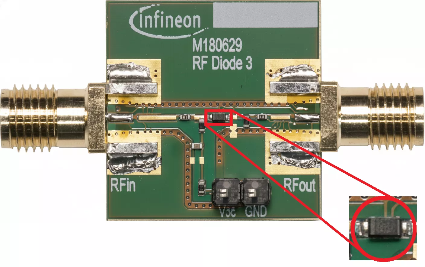
A very small SMD diode is placed directly on an RF signal path, close to an antenna or RF IC.
What type of diode is this?
What is a Diode?
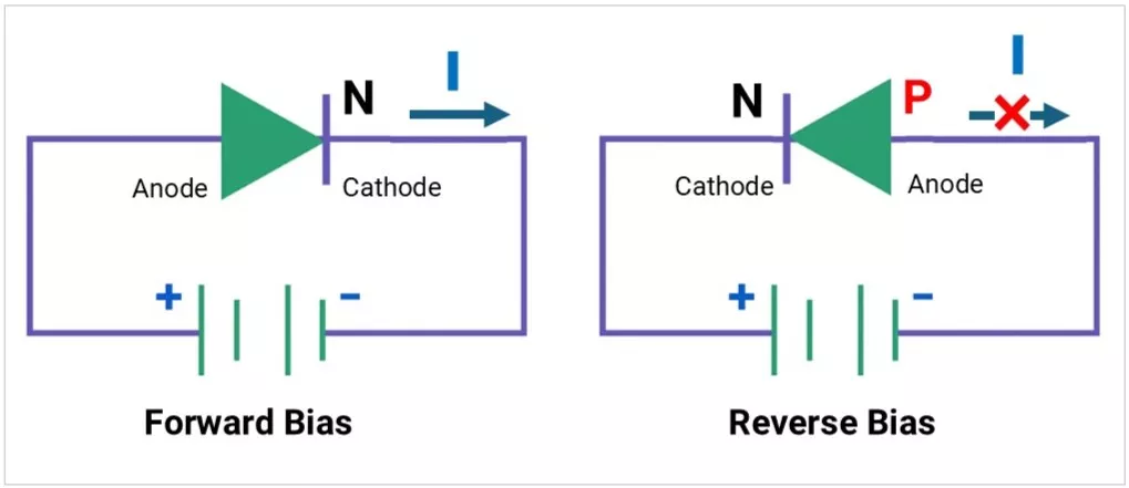
A diode is a two-terminal semiconductor device that allows current to flow in one direction (forward) and blocks it in the opposite direction (reverse).
It acts as an electrical one-way valve, protecting and controlling circuits.
Key Points:
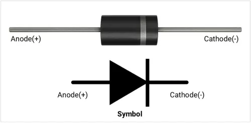
Polarity: Anode (+) and Cathode (–).
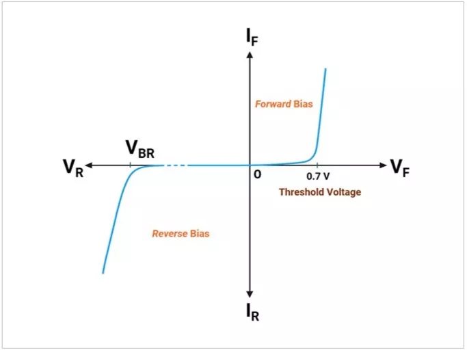
- Forward voltage drop (VF): Voltage needed for conduction. Forward conduction begins when VF reaches the threshold voltage:
- Silicon: 0.6–0.7 V
- Schottky: 0.15–0.45 V
- Germanium: 0.2–0.3 V
Diode Forward and Reverse Biased Connections
Diode Forward and Reverse Biased Voltage–Current (V–I) Curve
Practical Use Cases of Diodes
- Rectification: Converting AC to DC (half-wave, full-wave, bridge).
- Reverse Polarity Protection: Prevents damage if the supply is connected in reverse.
- Voltage Regulation: Using Zener diodes to maintain a fixed voltage.
- Signal Demodulation: Extracting audio from AM radio signals.
- Waveform Shaping: Clipping and clamping circuits.
- Freewheeling/Flyback Protection: Protects switching devices from inductive spikes.
- Light Emission: LEDs, IR diodes, laser diodes.
- ESD Protection: Protecting ICs from electrostatic discharge.
- RF Mixing & Detection: Schottky diodes in RF circuits.
- Overvoltage Suppression: TVS diodes in automotive or industrial electronics.
Types of Diodes
A. Based on Construction / Material
- Silicon – General use.
- Germanium – Low VF, RF detection.
- Gallium Arsenide – Optoelectronics, high-frequency.
B. Based on Function
| Type | Image | Symbol | Description | Common Use |
|---|---|---|---|---|
General-Purpose Rectifier (1N400x)
| 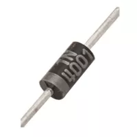 | 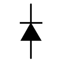 | Standard recovery speed, low cost. | Power supplies. |
| Fast Recovery Diode | 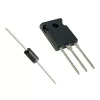 | | Short reverse recovery time. | SMPS, high-frequency circuits. |
| Schottky Diode | 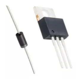 | 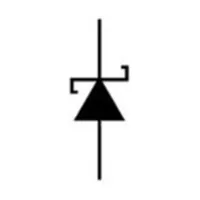 | Low VF, fast switching. | Low-voltage rectifiers, reverse protection. |
| Zener Diode | 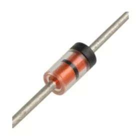 | 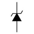 | Controlled reverse breakdown voltage. | Voltage regulation, reference. |
| LED | 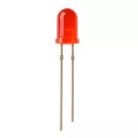 | 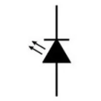 | Emits light when forward-biased. | Indicators, illumination. |
| Photodiode | 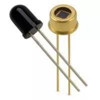 | 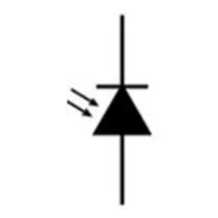 | Generates current when exposed to light. | Light sensing. |
| Laser Diode | 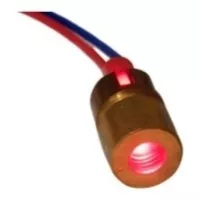 | 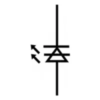 | Coherent light emission. | Optical communication, laser pointers. |
| Tunnel Diode | 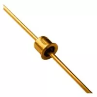 |  | Negative resistance region. | Microwave oscillators. |
| Varactor Diode | 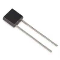 | 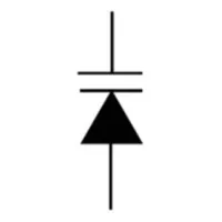 | Voltage-controlled capacitance. | RF tuning. |
| Avalanche Diode | 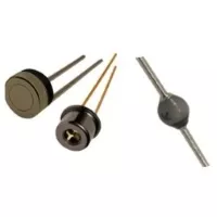 | 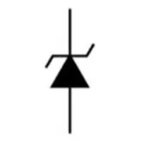 | High-voltage breakdown behavior. | Surge handling. |
| TVS Diode | 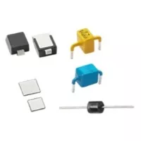 | 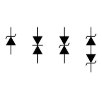 | Absorbs high-energy transients, spikes. | ESD and surge protection. |
| PIN Diode | 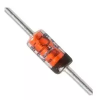 |  | High-frequency switching, low distortion. | RF switches and attenuators. |
Diode Key Specifications
- Forward Voltage Drop (VF) – Voltage needed for conduction; lower = better efficiency.
- Silicon: ~0.6 - 0.7V
- Germanium: ~ 0.2 - 0.3V
- Schottky: ~0.15 - 0.45V
- LED: ~1.8 - 3.6V depending on color.
- Maximum Reverse Voltage (VRRM) – The Highest reverse voltage a diode can block before breakdown.
- Maximum Average Forward Current (IF(AV)) – Continuous current a diode can conduct safely.
- Surge Forward Current (IFSM) – Short pulse capability, e.g., startup surge in rectifiers.
- Reverse Leakage Current (IR) – small current flows when the Diode is in reverse bias. Higher in Schottky diodes.
- Reverse Recovery Time (trr) – Time taken to stop conducting when switching from forward to reverse bias.
- Standard: ~2–30 µs
- Fast recovery: <500 ns
- Schottky: ~ns range.
- Junction Capacitance (CJ) –Acts like a capacitor in reverse bias; matters in RF/high-speed use
- Thermal Resistance (RθJA / RθJC) – Indicates how well the diode dissipates heat. Lower values mean better cooling and higher reliability
- Power Dissipation (PD) – Maximum heat the diode can safely handle before failure.
- Temperature Coefficient – Shows how VF and breakdown voltage vary with temperature (VF decreases as temperature rises).
Example 1N4001 diode Specifications:
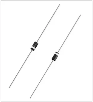
| Specification | Value (Diotec 1N4001) |
|---|---|
| Forward Voltage Drop (VF) | < 1.1 V (at IF = 1 A, Tj = 25°C) |
| Maximum Reverse Voltage (VRRM) | 50 V |
| Maximum Average Forward Current (IF(AV)) | 1 A (at TA = 75°C) |
| Surge Forward Current (IFSM) | 27 A (50 Hz half sine-wave, 10 ms) 30 A (60 Hz half sine-wave, 8.3 ms) |
| Reverse Leakage Current (IR) | < 5 µA (at VR = 50 V, Tj = 25°C) < 50 µA (at VR = 50 V, Tj = 100°C) |
| Reverse Recovery Time (trr) | Typ. 1500 ns (1.5 µs) (IF = 0.5 A to IR = 1 A to 0.25 A) |
| Junction Capacitance (CJ) | Typ. 15 pF (at VR = 4 V, f = 1 MHz) |
| Thermal Resistance | RθJA: Typ. 45 K/W (Junction to Ambient) RθJL: Typ. 15 K/W (Junction to Leads) |
| Power Dissipation (PD) | Not explicitly listed as a static value. (Limited by the maximum junction temperature of Tj = 175°C and the thermal resistance). |
| Temperature Coefficient | Not explicitly listed as a singular metric. (Operating junction temperature range is -50°C to +175°C; datasheet curves show VF decreasing as temperature rises). |
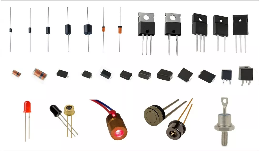
Diode Packages
A. Through-Hole
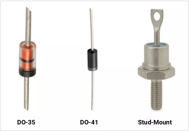
B. SMD
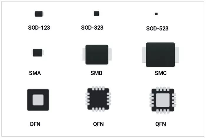
C. Special
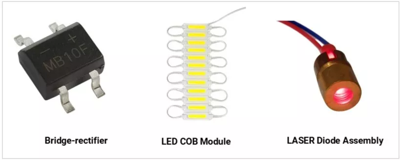
Diode Identification in Practice
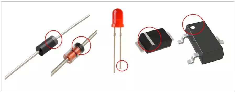
Cathode Identification Markings
- Polarity: Cathode marked with a band, stripe, or dot.
- SMD marking: Cathode side often marked with a line/bar.
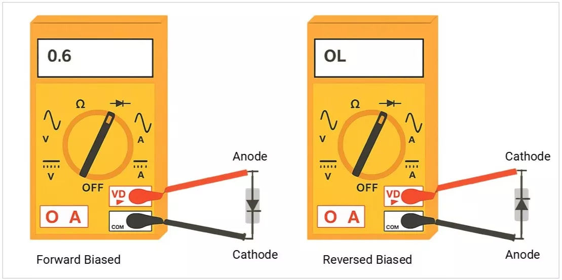
Anode and Cathode Identification using Multimeter
Use a multimeter in diode mode (forward direction shows ~VF, reverse shows OL).
SMD Diode Marking Table
Reminder: SMD diode markings are not globally standardized. Always confirm with the manufacturer’s datasheet when identifying unknown diodes.
| Marking | Images | Diode Type / Part No. | Package | Notes |
|---|---|---|---|---|
| A1 | 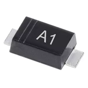 | BAV99 (dual switching diode) | SOT-23 | 100 V, 215 mA dual small-signal switching diode |
| A2 | 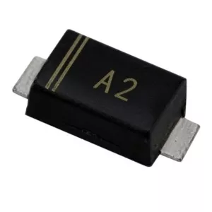 | BAV70 (dual switching diode) | SOT-23 | 70–100 V, 200 mA dual small-signal switching diode |
| T4 | 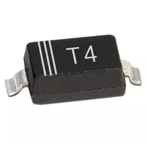 | 1N4148W (fast switching diode) | SOD-123 | 100 V, 150–200 mA fast switching |
| SS14 | 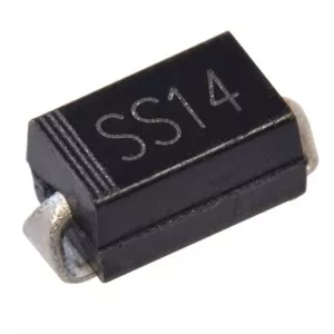 | Schottky rectifier | DO-214AC (SMA) | 40 V, 1 A, low forward drop |
| SS16 | 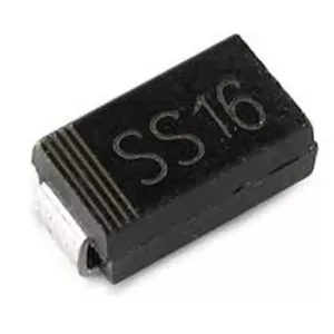 | Schottky rectifier | DO-214AC (SMA) | 60 V, 1 A, higher VR version of SS14 |
| S4 | 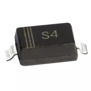 | Alias for SS14 (Schottky) | DO-214AC (SMA) | Manufacturer-dependent code (not unique) |
Standard Values & Ratings
- Zener voltages: 3.3V, 4.7V, 5.1V, 6.2V, 9.1V, 12V, 15V, 24V, etc.
- LED VF: Red ~1.8V, Green ~2.0V, Blue/White ~3.0–3.6V.
- Common parts: 1N4148 (fast signal), BAT54 (Schottky), 1N5408 (high current).
How to Select a Diode
- Match the Application
- Rectifier: For AC–DC conversion (power supplies).
- Clamping/Protection: For voltage limiting or surge protection (TVS/Zener).
- Regulation: Zener diodes for fixed reference voltages.
- Light Emission: LEDs for indication or illumination.
- Sensing: Photodiodes for light detection.
- Voltage Rating (VRRM)
- Choose at least 2× the peak reverse voltage expected in the circuit to ensure safe operation and margin against spikes.
- Current Rating (IF(AV))
- Select ≥ 1.5× the maximum load current to handle continuous operation and occasional surges.
- Switching Speed
- For low-frequency rectification, standard diodes (like 1N400x) are fine.
- For high-frequency circuits (SMPS, RF), use Schottky (very fast, low VF) or fast recovery diodes.
- Thermal Considerations
- Check Power Dissipation (PD) and Thermal Resistance (RθJA / RθJC).
- Ensure proper heat sinking or package choice to avoid overheating.
- Special Requirements
- Low Leakage: Critical in precision or low-power circuits.
- LEDs: Select by wavelength, brightness, and viewing angle.
- Zener: Pick the breakdown voltage that matches your regulation needs.
Real-World Design Examples
- Reverse Polarity Protection: Schottky in series with the supply in the IoT board.
- 5.1V Zener Regulation: Reset line clamp in MCU circuits.
- Flyback Diode: Across motor driver outputs.
- USB ESD Protection: Low-capacitance TVS diodes on D+/D– lines.
- Bridge Rectifier: 230VAC to DC conversion in SMPS.
Common Failure Modes
- Shorted Diode: Caused by overcurrent or overvoltage.
- Open Circuit: Physical damage or overheating.
- Increased Leakage: Aging or heat damage.
- LED Dim/Fail: Overcurrent or thermal degradation.
Safety & Handling
- Always observe polarity when soldering.
- Use heatsinking for high-power diodes.
- ESD precautions for sensitive types.
- Avoid exceeding surge current ratings.