35. LED Electrical Characteristics
Question.4
You’re using a SMD LED.
Consider-
- Typical forward voltage VF≈3.2V at 20 mA.
- Thermal resistance (junction-to-ambient, RθJA) ≈ 200 °C/W.
- Max junction temperature = 125 °C.
Scenario: The LED runs at I_F = 20 mA, ambient = 40 °C.
What will be the approximate junction temperature (Tj)?
What is an LED?
- A Light Emitting Diode is a PN‑junction device that emits photons when forward‑biased (electroluminescence).
- It’s optimized for light output, not rectification.
LED and connections diagram:
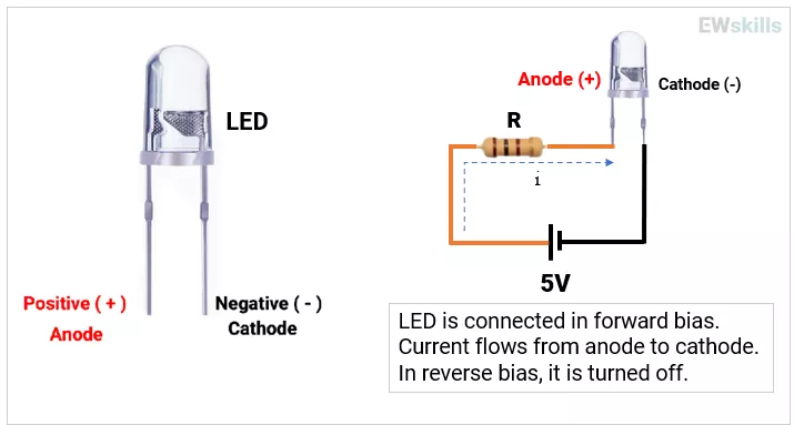
- Conduction: Turns ON when LED’s forward voltage (VF) is reached; current must be limited externally or by a driver.
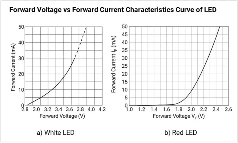
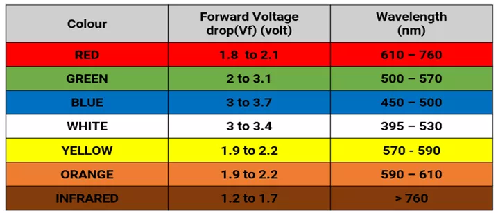
- VF ranges (typical):
- Red/IR ~1.6–2.0 V,
- Green/Yellow ~2.0–2.4 V,
- Blue/White ~2.8–3.6 V.
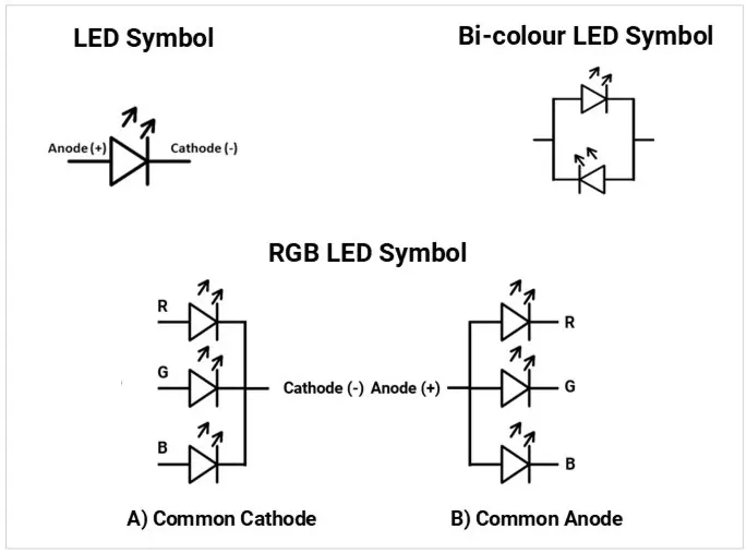
LED schematic symbol (fixed, RGB, bicolor)
IV curve (VF vs IF) from datasheet for red & white LEDs
Practical Use Cases
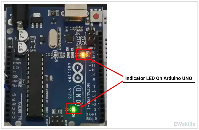
1) Status indicators (power, fault, communication).
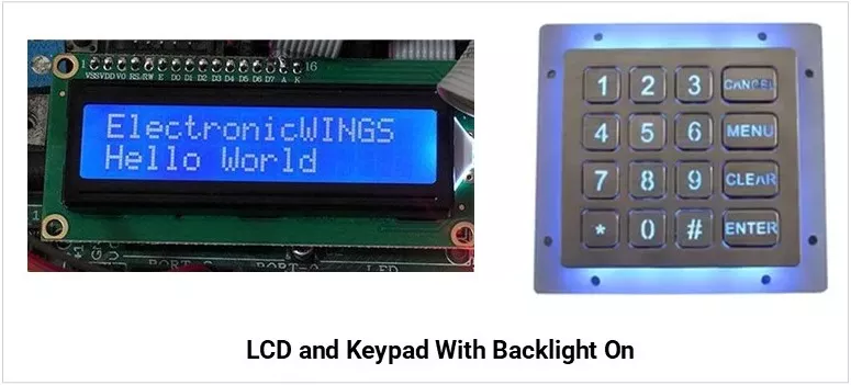
2) Backlighting (LCDs, keypads).
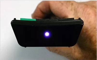
3) IR communication (TV remotes, proximity).
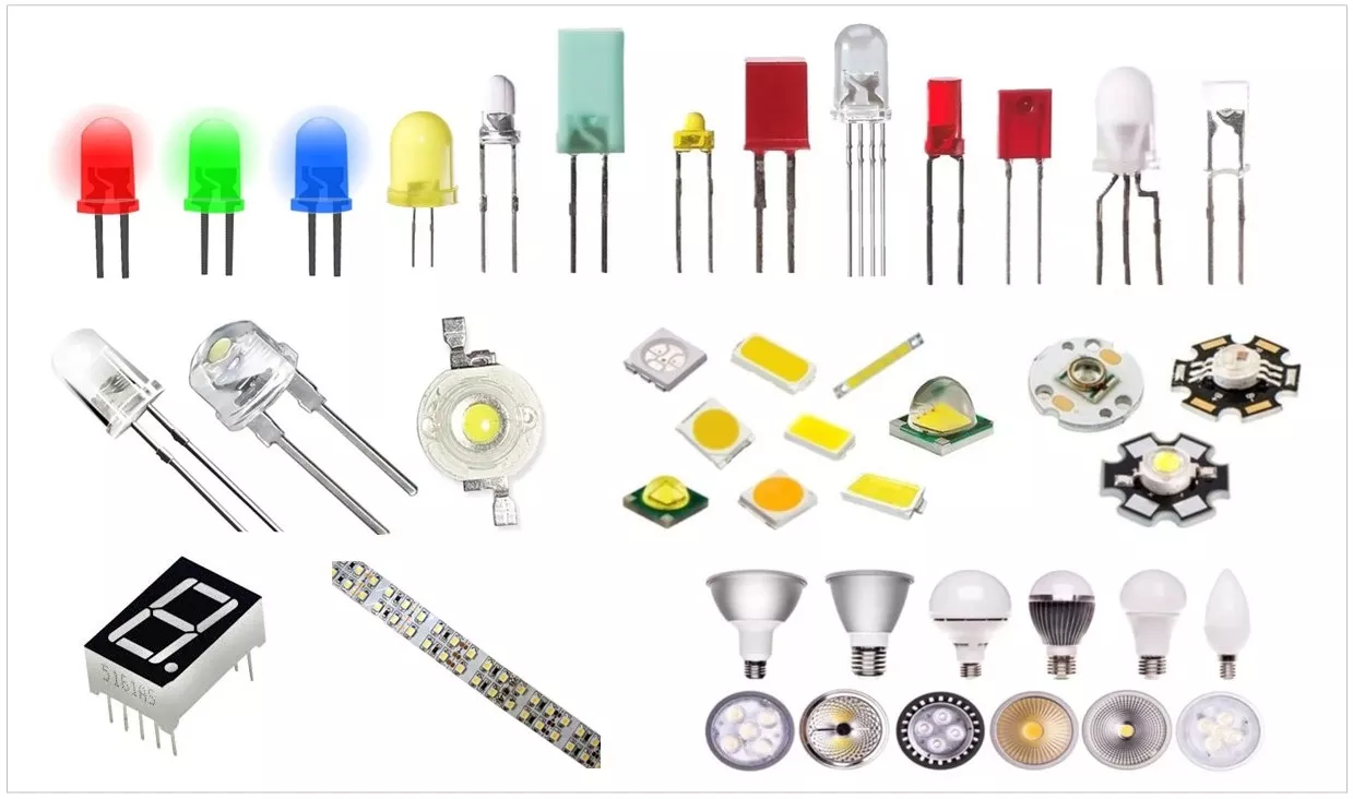
Types of LEDs
| Type | Image | Description |
|---|---|---|
| Through-Hole LEDs | 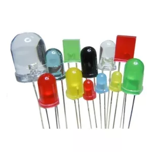 |
|
| Surface Mount LEDs (SMD) | 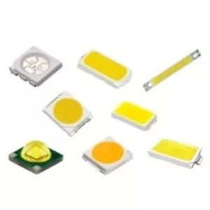 |
|
| UV LEDs | 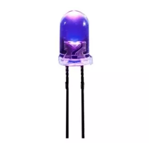 |
|
| High-Power LEDs | 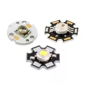 |
|
| RGB LEDs | 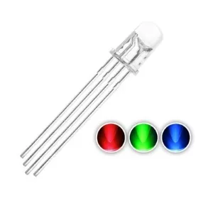 |
|
| Bi-Colour LEDs | 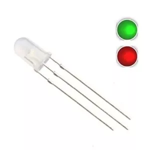 |
|
Key Specifications
- VF (Forward Voltage): Voltage across LED at a given IF; varies with LED color (material bandgap), applied current, and temperature.

- IF (Forward Current): It determines LED brightness and heating.
It must always be kept below the Absolute Maximum Rating to avoid damage.
Example: For a 20 mA LED, the recommended IF might be 10–15 mA for long life. - IFP (Peak/Pulse Current): Short pulses allowed under specific duty cycles.
Typical limit of duty cycle: ≤ 1%–10%, depending on LED. - Luminous intensity (mcd) vs Luminous flux (lm):
- Luminous intensity is the amount of light emitted in a specific direction. Unit: mcd (millicandela).
- Luminous flux is the total quantity of visible light emitted in all directions. Unit: lumen (lm).
- Design Rule: For indicators, use mcd (spot brightness), for lighting use lm (total illumination).
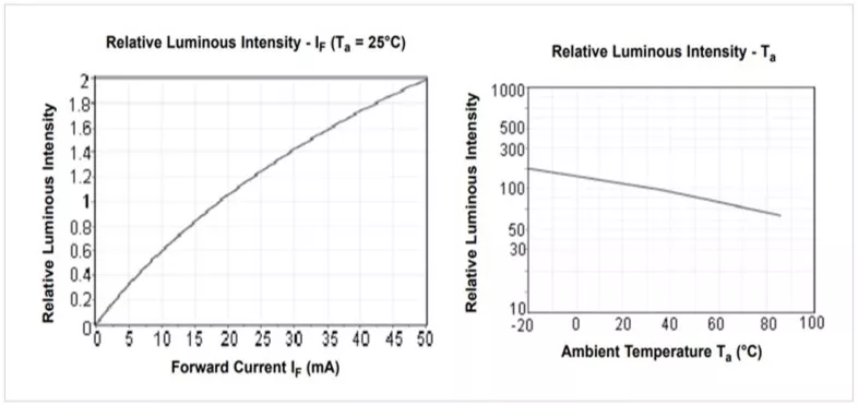
- Viewing angle (°): Beam spread; a narrower beam looks brighter head‑on.
- Wavelength (nm) / Dominant wavelength: Color accuracy for mono color LEDs.
- Correlated Color Temperature (CCT): CCT describes the apparent color of white light from an LED, expressed in Kelvin (K).
- Low CCT → Warm, relaxing light (residential, decorative).
- High CCT → Cool, stimulating light (offices, hospitals, outdoor, industrial).
- Color Rendering Index (CRI) – color accuracy for illumination.
- Thermal resistance (RθJA/RθJB/RθJS): Junction‑to‑ambient/board/solder; lower is better.
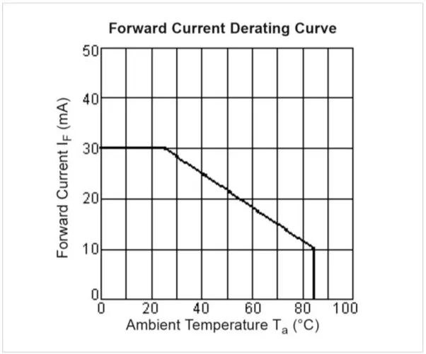
- Power dissipation & derating: Max heat the LED can dissipate; check derating vs temperature.
Derating Curve : (Understand the curve carefully- although max current rating is 30mA- it declines over the Temperature rise. While operating in High ambient temperature- need to consider the curve)
- Reverse voltage (VR): Often very low; avoid reverse bias or provide a protection diode.
Example Würth Elektronik 151051RS11000 (WL-TMRC series) 5mm red LED specifications:
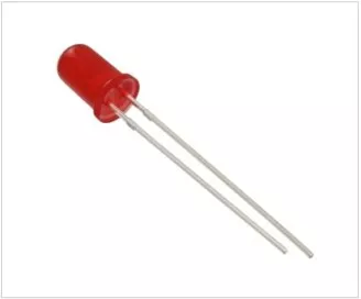
| Specification | Value |
|---|---|
| VF (Forward Voltage) | Typical: 2.1 V; Maximum: 2.5 V (at IF = 20mA) |
| IF (Forward Current) | Absolute Maximum: 30 mA; Test/Recommended: 20 mA |
| IFP (Peak/Pulse Current) | 100 mA (Condition: 1/10 duty cycle @ 1 kHz) |
| Luminous Intensity (mcd) | 30 mcd (Typical at 20 mA) |
| Luminous Flux (lm) | Not specified (Standard indicator; use 30 mcd for spot brightness) |
| Viewing Angle (°) | 60° |
| Wavelength (nm) | Dominant: 645 nm; Peak: 650 nm |
| Power Dissipation | 75 mW |
| Derating Curve | Continuous current starts at 20 mA and begins to decline linearly after ~55°C ambient temperature (TA) |
| Reverse Voltage (VR) | 5 V (Maximum) |
Packages & Footprints (what to recognize on a PCB)
| Package Type | Image | Physical Features & Recognition | Common Package / Case |
|---|---|---|---|
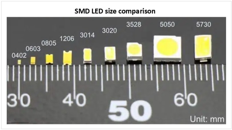
| Standard SMD | 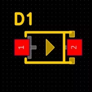 | Tiny rectangular blocks. Look for side pads (terminations) and a clear/yellow top emitter window. Often features a polarity mark (green line or notched corner). | 0402, 0603, 0805, 1206 |
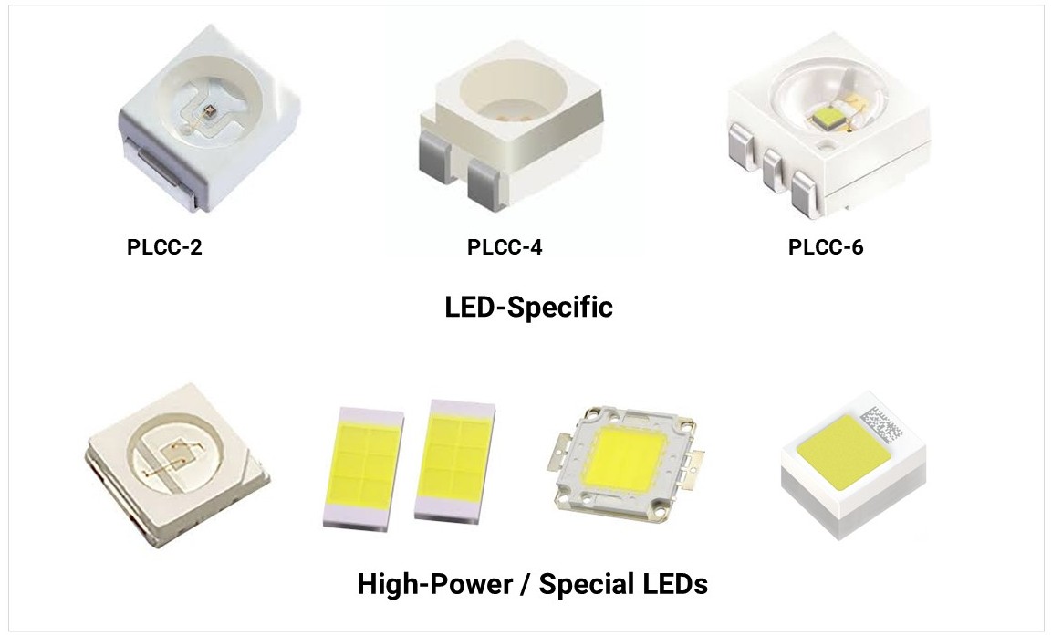
| PLCC (Plastic Leaded Chip Carrier) | 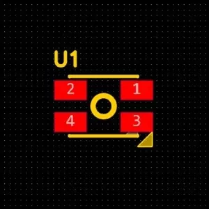 | Larger, square plastic bodies with legs folded under or along the sides. Usually has a notched corner to indicate the Cathode. | PLCC-2, PLCC-4 |
| High-Power SMD | 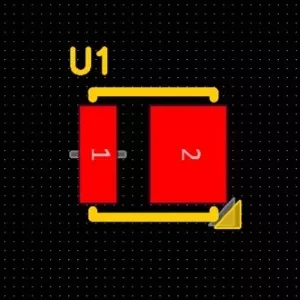 | Square ceramic or plastic base. Look for a large central thermal pad underneath the chip to transfer heat to the PCB. | 3535, 5050, 7070 |
| COB (Chip on Board[SS5] ) | 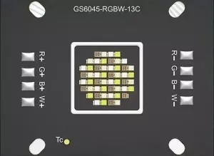 | A large yellow or orange phosphor area directly on a metal substrate. Usually mounted on a Metal Core PCB (MCPCB) with screw holes. | Circular or Square COB modules |
| Through-Hole | 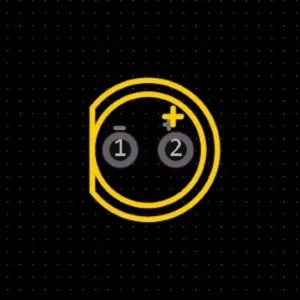 | Vertical cylinders with domed or diffused lenses. Identified on PCBs by two circular pads and a silkscreen "flat side" indicating the cathode. | 3 mm (T-1), 5 mm (T-1¾) |
Through Hole Types
| Type | Description | Applications | Image |
|---|---|---|---|
| Radial LED | Leads come out from the bottom of the LED package (most common 3 mm, 5 mm, 10 mm LEDs). | General indicators, panel mount, displays. | 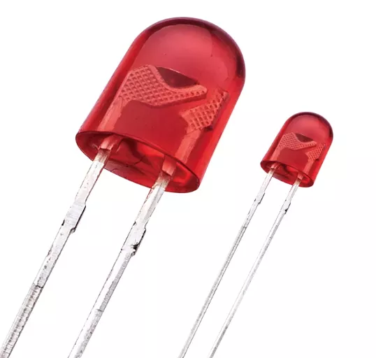 |
| Axial LED | Leads extend straight out from opposite sides of the package (like resistors/axial diodes). | Used in signage, backlighting, or tight horizontal layouts. | 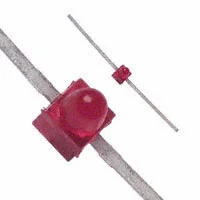 |
SMD LED Package Classification
| Category | Imperial Code | Metric Code | Dimensions (mm) | Typical Power |
|---|---|---|---|---|
| Standard EIA Sizes | 0201 | 0603 | 0.6 × 0.3 | <0.01 W (indicator only) |
| 0402 | 1005 | 1.0 × 0.5 | <0.02 W | |
| 0603 | 1608 | 1.6 × 0.8 | 0.02–0.05 W | |
| 0805 | 2012 | 2.0 × 1.25 | 0.05–0.1 W | |
| 1206 | 3216 | 3.2 × 1.6 | 0.05–0.1 W | |
| 1210 | 3225 | 3.2 × 2.5 | 0.1–0.2 W | |
| 3528 | 3528 | 3.5 × 2.8 | 0.1–0.2 W | |
| 2835 | 2835 | 2.8 × 3.5 | 0.2–0.5 W | |
| 3014 | 3014 | 3.0 × 1.4 | 0.05–0.2 W | |
| 3020 | 3020 | 3.0 × 2.0 | 0.05–0.2 W | |
| 3030 | 3030 | 3.0 × 3.0 | 0.5–1.0 W | |
| 4014 | 4014 | 4.0 × 1.4 | 0.2–0.5 W | |
| 5050 | 5050 | 5.0 × 5.0 | 0.2–0.5 W per die (RGB = 3 dies → up to 1.5 W) | |
| 5630 | 5630 | 5.6 × 3.0 | 0.5–1.0 W | |
| 5730 | 5730 | 5.7 × 3.0 | 0.5–1.0 W | |
| 7070 | 7070 | 7.0 × 7.0 | 2.0–3.0 W+ |
| Category | Metric Code | Dimensions (mm) | Typical Power |
|---|---|---|---|
| LED-Specific | PLCC-2 | ~3.5 × 2.8 | 0.05–0.2 W |
| PLCC-4 | ~5.0 × 5.0 | 0.2–0.6 W (RGB total) | |
| PLCC-6 | ~5.0 × 5.0 | 0.3–0.9 W (RGB total) | |
| High-Power / Special | 3535 | 3.5 × 3.5 | 1.0–3.0 W |
| 7575 | 7.5 × 7.5 | 3.0–5.0 W | |
| CSP | ≈1–2 mm | 0.1–1.0 W | |
| COB | Multi-die arrays | 5–50+ W | |
| Ceramic SMD | Varies | 1–5 W typical |
LED Polarity identification and testing.
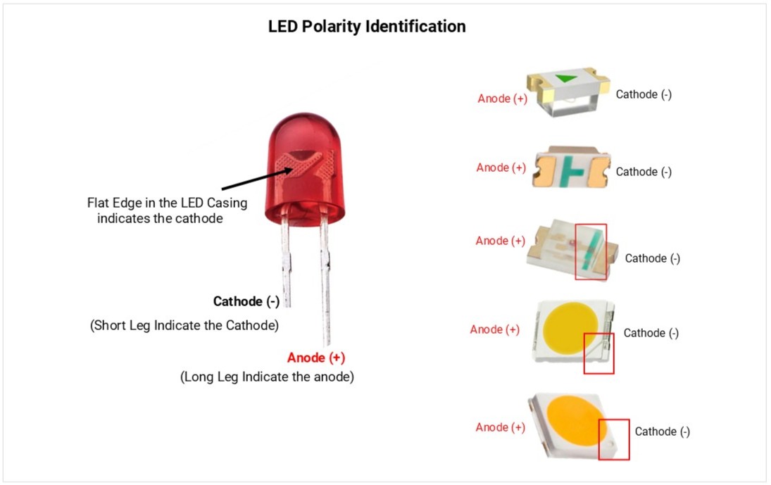
LEDs are polarized; current only flows from Anode (+) to Cathode (-).
1. Visual Identification
- Anode (+): Longer lead; round casing side.
- Cathode (-): Shorter lead; flat edge on the casing; internal "anvil" (larger metal part).
- SMD (Surface Mount): A printed line, dot, or notch indicates the Cathode.
2. Multimeter Testing (Diode Mode)
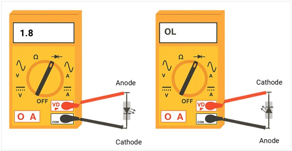
To verify polarity or health, touch the probes to the leads:
| Test Type | Connection | Result | Meaning |
|---|---|---|---|
| Forward Bias | Red (+) to Anode / Black (-) to Cathode | 1.7V – 3.0V | Functional; LED may glow. |
| Reverse Bias | Red (+) to Cathode / Black (-) to Anode | OL | Correct; blocking current. |
3. Diagnostic Results
- Healthy: Shows voltage in forward bias and OL in reverse.
- Faulty (Open): Shows OL in both directions (internal break).
- Faulty (Short): Shows 0.00 in both directions (internal fuse).
Standard Voltage & Wavelength
- Indicator LED’s Forword current (IF): 2–20 mA (many are visible at 1–2 mA with high‑efficiency types).
- High‑power LED’s Forword current (IF): ~350 mA (1 W), 700 mA (3 W), 1 A+ (5 W+).
- Common wavelengths: IR 850/940 nm; Red 620–630 nm; Green 520–530 nm; Blue 460–470 nm; UV 365–400 nm.
- Common packages: Through hole, 0805/1206 (indicator), 2835/3030/3535/5050/7070 (power/RGB), COB modules.
How to Select an LED (step‑by‑step)
- Understand the application: Indicator? Backlight? Illumination? IR/UV? RGB effects?
- Pick color/wavelength or CCT/CRI:
- Indicators: choose color for contrast; use narrow beam for bright “dot”.
- Illumination: choose CCT (e.g., 3000 K warm) and CRI (≥80 or ≥90 for color‑critical).
- Set brightness target:
- Select LEDs by reviewing datasheets for high luminous intensity (millicandela/mcd) and proper viewing angles.
- Choose electrical approach: Resistor (simple), constant‑current driver (recommended for power/RGB/precision).
- Budget voltage/current: Verify supply headroom for max IF (Forward current) and VF (Forward Voltage). consider ambient temperature.
- Thermal plan: Estimate power → Rθ path → heatsink/copper/MCPCB.
- Package & assembly: THT vs SMD; reflow vs hand solder; lens/mechanical constraints.
- Reliability: Check derating, ESD, MSL, sulfur resistance (for environments with sulfides).
Series / Parallel & Arrays (don’t fry LEDs)
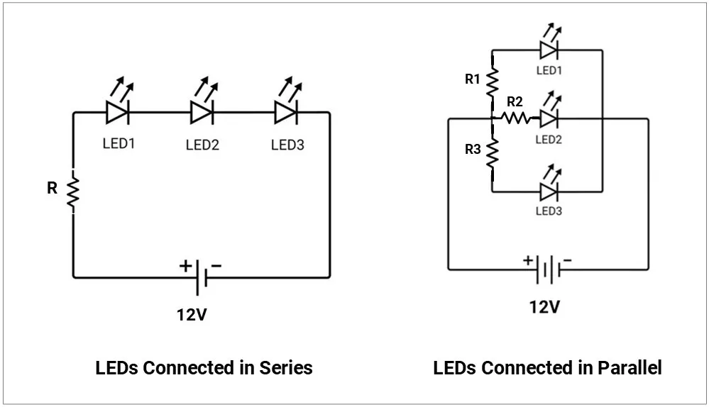
- Series preferred for equal current through each LED.
- Parallel pitfalls: Current hogging due to VF mismatch → one LED overheats.
- If you must parallel, give each LED its own resistor or use current-sharing circuitry.
- Matrix/multiplexing: Consider duty cycle; increase peak current within IFP limits to maintain average brightness; watch eye‑safety with IR/UV.
Common Failure Modes & Field Issues
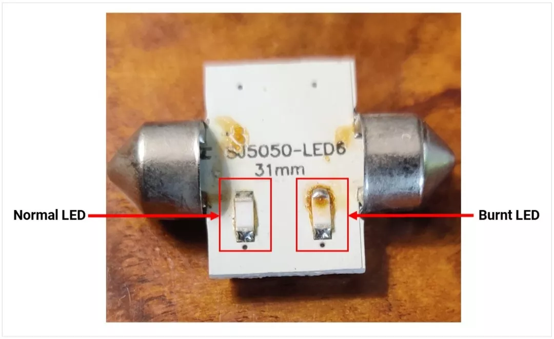
- Overcurrent/overheat: Open circuit or dark/weak LED; lumen depreciation (L70 reached early).
- ESD damage: Partial shorts/leakage; dim or intermittent behavior.
- Color shift: Phosphor aging in white LEDs; visible tint change.
- Sulfur corrosion: Blackening of silver‑plated leadframes (harsh environments).
- Moisture popcorning: Cracks after reflow if MSL not respected.
- Optics degradation: Lens yellowing/clouding with heat/UV.
Normal vs Burnt LED Image:
LED Insights
- Luminous intensity vs viewing angle
- Luminous intensity (mcd) indicates how bright an LED appears in a specific direction
- LEDs with a narrow viewing angle:
- Light is more focused
- Appears brighter (higher mcd)
- LEDs with a wide viewing angle:
- Light spreads out more
- Appears less bright
- High mcd LEDs are preferred for indicators for better long-distance visibility
- Wavelength & color
- LED color is defined by its wavelength (in nm)
- Infrared: ~760 nm+ (used in remotes, cameras)
- Visible: ~450–760 nm (blue to red)
- UV: ~365–400 nm
- Narrow spectral output results in a purer and more saturated color
- Color temperature (CCT) – white LEDs
- Measured in Kelvin (K), indicates light tone
- 2700–3000 K: Warm (yellowish, home use)
- 3500–4100 K: Neutral (offices)
- 5000–6500 K: Cool (industrial, hospitals)
- High temperature or current can shift color (usually toward blue)
- Hue (color type)
- Represents the actual color, linked to wavelength
- Expressed as an angle (0°–360°):
- Red: 0°
- Green: 120°
- Blue: 240°
- RGB mixing can generate any color
- Saturation (color purity)
- Defines how pure or washed-out a color is
- 100% → Pure, vivid color
- 0% → White/gray
- Adding more colors reduces saturation
- Intensity (brightness)
- Represents total light output
- Controlled using PWM (Pulse Width Modulation):
- 0% → Off
- 100% → Maximum brightness
- Allows brightness control without affecting color
- HSI vs RGB (for programming)
- Hue: Sets color
- Saturation: Controls color purity
- Intensity: Controls brightness (via PWM)
- HSI is more intuitive compared to raw RGB values