
34. NTC Selection & Design
Question.7
A power supply is turned ON and OFF repeatedly within 1 to 5 seconds during testing.
Which input protection component may fail to do its job properly in this rapid power-cycling condition?
What is an NTC Inrush Current Limiter?
An NTC (Negative Temperature Coefficient) inrush current limiter is a thermistor-based passive component that suppresses the initial surge of current when a device is powered on.
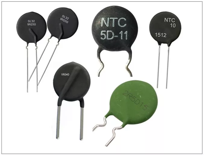
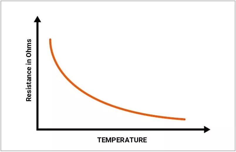
At room temperature, the NTC presents high resistance, limiting inrush current. As current flows, the device self-heats and its resistance drops — allowing normal current to pass with minimal loss.
Core principle: High resistance when cold → Low resistance when hot.
Why is Inrush Current a Problem?
When equipment with large input capacitors (SMPS, LED drivers, motor drives) is powered on, uncharged capacitors behave like a near short circuit. This causes a current spike — often 10× to 100× steady-state — lasting a few milliseconds.
This spike can trip breakers, blow fuses, weld relay contacts, stress rectifier diodes, reduce capacitor life, and cause voltage dips on shared power rails.
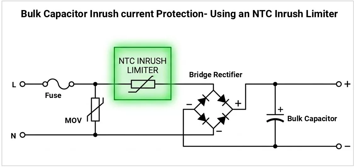
An NTC in series with the input absorbs this energy and limits peak current to a safe level.
How Does It Work?
Phase 1 — Cold State (Power-On) At room temperature, the NTC presents its full rated resistance (R₂₅), limiting peak inrush:
I_peak ≈ V_peak / R₂₅
Example: On 230V AC (325V peak), a 10Ω NTC limits surge to ~32.5A instead of potentially hundreds of amps.
- Phase 2 — Hot State (Steady State) Within seconds, self-heating drops resistance to 10–20% of R₂₅. That same 10Ω NTC may settle at 0.5–1Ω, dissipating only a fraction of a watt.
- Key limitation: If power is cycled quickly (off and back on within seconds), the NTC hasn't cooled back to high resistance — it won't provide full protection on the next turn-on. Typical cooldown: 30–90 seconds depending on size and airflow.
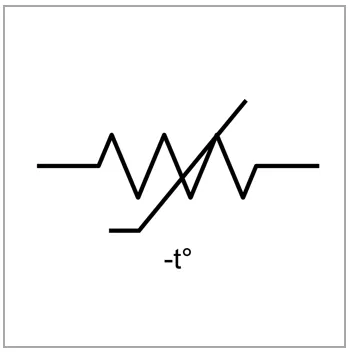
Symbols
Practical Use Cases
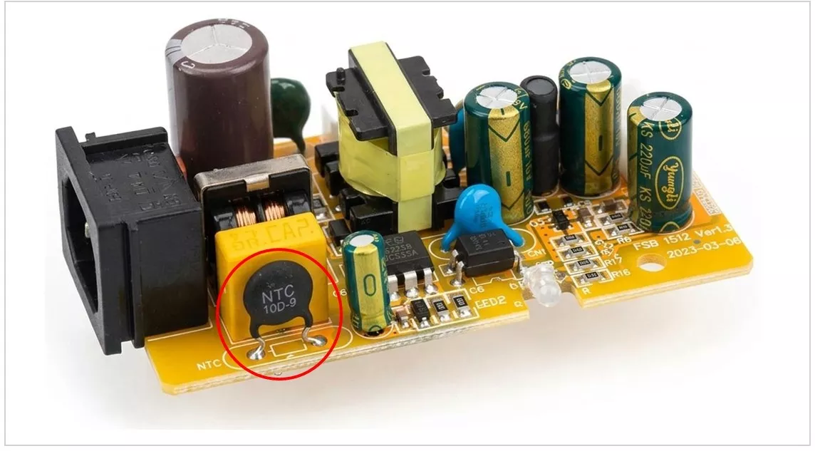
- Switch-Mode Power Supplies (SMPS) – Most common use. Placed at AC input (after fuse, before bridge rectifier) to limit bulk capacitor charging current. Found in PC PSUs, telecom rectifiers, and industrial converters.
- LED Drivers – Prevents tripping upstream breakers, especially when multiple drivers share a branch circuit.
- Motor Drives and Inverters – VFDs and servo drives use NTCs to protect input stages during DC bus capacitor charging.
- Battery Chargers – Protects connectors and input components from capacitor charging surges.
- Audio Amplifiers – Softens turn-on surge from large toroidal transformers and filter capacitors in Class AB amplifiers.
- UPS and Inverter Systems – Manages DC bus capacitor charging surges in both online and offline topologies.
Key Specifications
- Resistance at 25°C (R₂₅): The "cold" resistance that determines peak inrush limiting. Higher R₂₅ = more limiting but more initial voltage drop. Typical range: 0.5Ω to 120Ω.
- Maximum Steady-State Current (I_max): Maximum continuous current in the heated state. Always select for at least 1.25–1.5× your circuit's operating current.
Maximum Energy Rating (Joules): Energy the NTC can absorb in a single inrush event. Must exceed the capacitor stored energy:
E = ½ × C × V_peak²
Select with at least a 1.5× margin.
- B-Value (Material Constant): Defines how steeply resistance changes with temperature (in Kelvin). Higher B-value = sharper transition from limiting to low-loss state. Typical: 2500–5000 K.
- Thermal Time Constant (Cooldown Time): Time to cool back to near R₂₅ after power-off. Directly affects power cycling protection. Typical: 30–90 seconds.
- Maximum Operating Temperature: At elevated ambient, the NTC starts with lower resistance, reducing its effectiveness. Typical limit: 85°C–150°C. Check R-T curve and derate accordingly.
- Residual Resistance (Hot Resistance): Steady-state resistance when fully heated. Lower = less ongoing power loss. Estimate steady-state dissipation as P = I² × R_hot.
Naming Convention
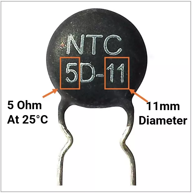
NTC inrush limiters use a simple code printed on the body:
Format: [R₂₅][D][Disc Diameter in mm]
5D-11 → 5Ω at 25°C, disc type, 11mm diameter 10D-20 → 10Ω at 25°C, disc type, 20mm diameter
Larger disc = higher energy capacity, higher current rating, and longer cooldown time.
Manufacturers like Ametherm, Vishay, and TDK/EPCOS use their own part numbers, but R₂₅ and current ratings are always in the datasheet.
How to Select an NTC Inrush Current Limiter
- Step 1 — Determine R₂₅: R₂₅(min) ≈ V_peak / I_inrush(max). Target inrush is typically 30–50A for standard equipment.
- Step 2 — Check energy rating: Calculate E = ½ × C_total × V_peak² and select an NTC rated above this with margin.
- Step 3 — Verify steady-state current: NTC's I_max must exceed your circuit's operating current.
- Step 4 — Evaluate steady-state loss: If P = I² × R_hot is unacceptable for thermal or efficiency reasons, use NTC + bypass relay.
- Step 5 — Consider power cycling: If frequent on/off cycling is expected, a standalone NTC won't protect every time. Use relay bypass or time-delay interlock.
- Step 6 — Derate for ambient temperature: At high ambient, R₂₅ is already lower. You may need a higher-rated NTC or alternative approach.
Common Design Mistakes
- Undersizing energy rating – Calculate ½CV² and add margin. Undersized NTCs degrade over repeated inrush events.
- Ignoring rapid power cycling – A hot NTC provides almost no protection on the second turn-on. This is the most overlooked failure mode in the field.
- No thermal derating – An NTC rated 10Ω at 25°C might only present 4–5Ω at 60°C ambient, significantly reducing its effectiveness.
- Skipping bypass relay in high-power designs – Above ~500W, NTC steady-state loss becomes significant. Relay bypass is the standard solution.
- Wrong placement – NTC goes after the fuse, before the bridge rectifier. Placing it after the rectifier doesn't protect the AC-side components.
Relay Bypass for NTC Inrush Limiter
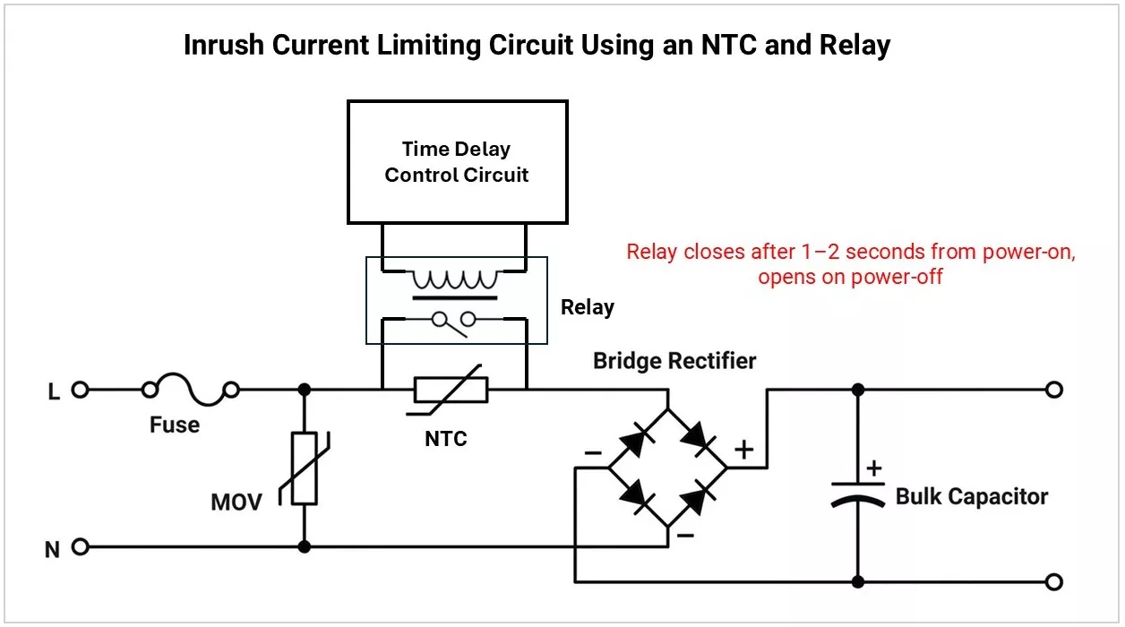
An NTC limiter works properly only when it is cold. After power ON, it becomes hot and its resistance drops very low.
If power turns OFF and ON again quickly, the hot NTC cannot limit the next inrush current well. So, a relay bypass is used to bypass the NTC during normal operation and keep it ready for fast power ON/OFF cycles.
NTC vs. Other Inrush Limiting Methods
| Method | Pros | Cons | Best For |
|---|---|---|---|
| NTC Thermistor | Simple, low cost | No quick-recycle protection, steady-state loss | Low-to-medium power SMPS (<500W) |
| NTC + Bypass Relay | Full protection every cycle, no steady-state loss | Added cost and complexity | High-power, mission-critical equipment |
| Fixed Resistor + Relay | Predictable (no temp dependence), full protection | Relay + control circuit needed | Industrial drives, UPS, high-reliability |
| Active Limiter (MOSFET) | Precise, fast, no mechanical wear | Complex, higher cost | Telecom, server PSUs, precision equipment |