64. 24V Input Optocoupler Selection
1. Component Purpose
Field-side 24V digital inputs carry noise from industrial wiring. Connecting these directly to a 3.3V MCU input would expose it to ground potential differences, common-mode noise, and transient spikes.
An optocoupler receives the 24V signal on its input LED (through a series resistor: R = (24V − 1.2V) / 10mA ≈ 2.2kΩ) and transfers the logic state to the MCU side through an isolated phototransistor output.
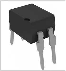
Required: Transistor Output · 1-Ch · ≥3000Vrms isolation · CTR ≥50% · Vout ≥30V · DIP-4 · Through Hole
2. How to Find It on DigiKey
Go to DigiKey.com → Isolators → Optoisolators → Transistor, Photovoltaic Output
Apply these filters:
- Voltage - Isolation → 3000Vrms or higher
- Output Type → Transistor
- Number of Channels → 1
- Current Transfer Ratio (Min) → 50% or higher
- Voltage - Output (Max) → 30V or higher
- Package / Case → 4-DIP
- Part Status → Active
Tip: The series resistor on the 24V input LED is critical. Calculate: R = (Vin − Vf) / If = (24 − 1.2) / 0.01 = 2.28kΩ. Use standard 2.2kΩ.
3. Key Specifications & What They Mean
| Specification | Required | Why |
|---|---|---|
| Output Type | Transistor | Simple ON/OFF signal isolation. |
| Channels | 1 | Single digital input. |
| Isolation | ≥3000Vrms | Protects MCU from field-side noise. |
| CTR (Min) | ≥50% | Reliable signal at ~10mA LED drive. |
| Vout Max | ≥30V | Margin for output-side voltage. |
| Package | 4-DIP | Through hole for prototyping. |
| Temp Range | −40°C to +85°C | Standard industrial range. |
| RoHS | Yes | Compliance required. |
4. Selecting a Safe, Production-Ready Part
The filtered list will show matching parts. Before you pick one, check: Is it Active? Is stock available? Is the manufacturer reputable? Is a datasheet available?
Full checklist: How to Select a Safe, Production-Ready Component — EWskills Guide
5. Filtered DigiKey Link
➡ View Matching Parts — Transistor, 1-Ch, ≥3000Vrms, CTR≥50%, DIP-4