29. ADC Serial plotter
Monitoring analog signals in real time is a core requirement in embedded system diagnostics. This task involves capturing analog voltage data using an onboard ADC and transmitting it over UART to visualize it through a serial plotter tool such as Arduino IDE Serial Plotter or similar PC-based software.
Key Concepts
- Analog-to-Digital Conversion (ADC)
- ADCs convert continuous analog signals (e.g., voltage from a sensor) into discrete digital values.
- UART Communication
- UART (Universal Asynchronous Receiver/Transmitter) is used for serial communication between the microcontroller and a PC.
- Data is transmitted asynchronously at a predefined baud rate (e.g., 115200 bps).
- Serial Plotter
- A tool (like the one in Arduino IDE) that visualizes incoming serial data in real-time.
General Approach
- Configure the ADC to read an analog input.
- Set up UART for serial communication.
- Continuously read ADC values and transmit them over UART.
- Visualize the data using a serial plotter.
Using Arduino IDE’s serial plotter
Arduino IDE has a serial plotter tool. We can open it by clicking below
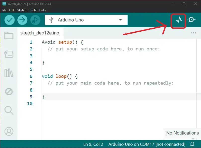
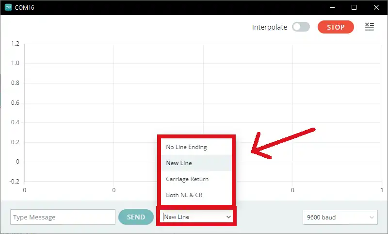
To plot data on the serial plotter, we need to simply send data to the Serial monitor with a new line (Serial.println()), where the new line separates the values.
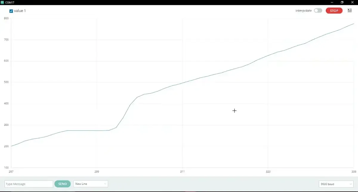
The serial plotter is one of the very useful features provided by the Arduino IDE. It is very easy to understand any data visually, rather than a list of numbers.
The multiple values can also be plotted simultaneously, using the “\t” tab. If we send 2 values with a tab separating them, both values will be plotted on the Serial plotter simultaneously.
Limitations
- There is no option for vertical and horizontal scrolling, which limits viewing the waveform over a time range.
So, by considering the above points, we can implement the task.
Below are the solutions to the given task using different microcontrollers
- STM32
- ESP32
- Arduino UNO
We’re using an STM32 NUCLEO-F103RB board, which runs at a 3.3V logic level.
Key Peripherals Used
- ADC1 Channel 0 (PA0): Reads the analog voltage from the potentiometer.
- USART2: For serial communication with a serial terminal to display voltage.
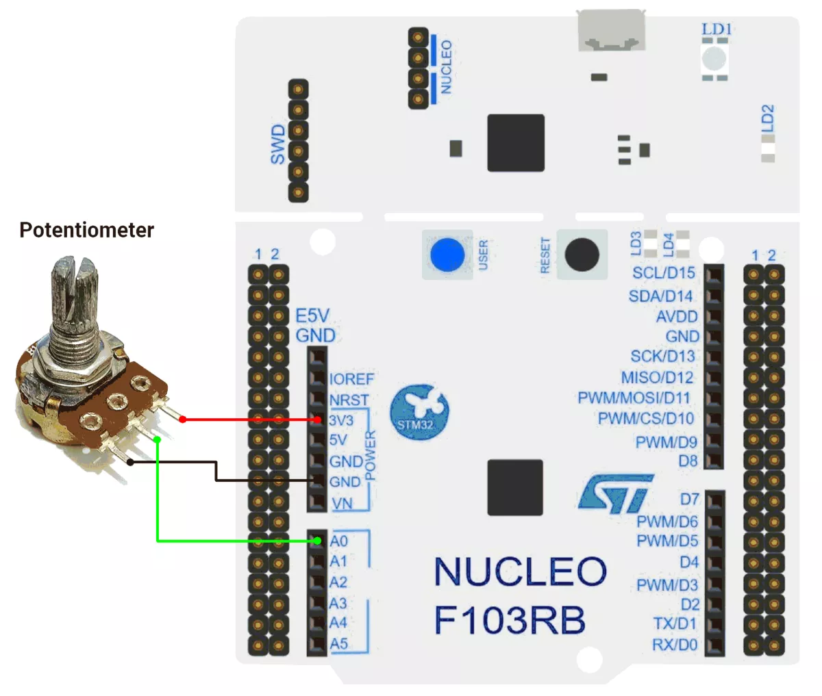
STM32 Hardware Connection
- Potentiometer connection:
- Connect the potentiometer’s middle pin (wiper) to PA0 (ADC1_IN0) for analog input.
- Connect the two outer pins of the potentiometer to 3.3V (VCC) and GND to form a voltage divider.
- Use a 10 kΩ potentiometer for best results.
- Use USART2 on the STM32 board for serial communication via the USB interface to transmit the measured analog values to a serial plotter.
Circuit Diagram
STM32 Firmware Implementation
Project Setup in STM32CubeIDE
- Create a Project
- Open STM32CubeIDE, start a new project, and select the NUCLEO-F103RB board.
- Basic Configuration (via CubeMX inside CubeIDE)
- Clock: Use the default HSI oscillator with PLL enabled (as configured in
SystemClock_Config). - GPIO: Enable clocks for PORTA, PORTB, PORTC, and PORTD.
- ADC1 (Analog Input Source)
- Resolution: 12-bit (0–4095 range).
- Conversion mode: Single, software-triggered.
- Channel: ADC_CHANNEL_0 (PA0).
- USART2: Enabled at 115200 baud, 8-N-1.
- Clock: Use the default HSI oscillator with PLL enabled (as configured in
- Code Generation
- CubeMX will automatically generate all the startup code, including:
HAL_Init()→ Initializes HAL and system tick.SystemClock_Config()→ Configures system clock (HSI + PLL).MX_GPIO_Init()→ Initializes GPIO ports.MX_USART2_UART_Init()→ Configures UART2.MX_ADC1_Init()→ Configures ADC1 for analog input.
- This code sets up the hardware and prepares the project for firmware development, so we only need to add our application logic in the user code sections
- CubeMX will automatically generate all the startup code, including:
Code Snippets from main.c
ADC Initialization (MX_ADC1_Init):
static void MX_ADC1_Init(void)
{
  ADC_ChannelConfTypeDef sConfig = {0};

  /** Common config
  */
  hadc1.Instance = ADC1;
  hadc1.Init.ScanConvMode = ADC_SCAN_DISABLE;
  hadc1.Init.ContinuousConvMode = DISABLE;
  hadc1.Init.DiscontinuousConvMode = DISABLE;
  hadc1.Init.ExternalTrigConv = ADC_SOFTWARE_START;
  hadc1.Init.DataAlign = ADC_DATAALIGN_RIGHT;
  hadc1.Init.NbrOfConversion = 1;
  if (HAL_ADC_Init(&hadc1) != HAL_OK)
  {
    Error_Handler();
  }

  /** Configure Regular Channel
  */
  sConfig.Channel = ADC_CHANNEL_0;
  sConfig.Rank = ADC_REGULAR_RANK_1;
  sConfig.SamplingTime = ADC_SAMPLETIME_13CYCLES_5;
  if (HAL_ADC_ConfigChannel(&hadc1, &sConfig) != HAL_OK)
  {
    Error_Handler();
  }

}
This configures ADC1 for single-channel operation with right-aligned 12-bit results.
UART2 Initialization (MX_USART2_UART_Init):
static void MX_USART2_UART_Init(void)
{
  huart2.Instance = USART2;
  huart2.Init.BaudRate = 115200;
  huart2.Init.WordLength = UART_WORDLENGTH_8B;
  huart2.Init.StopBits = UART_STOPBITS_1;
  huart2.Init.Parity = UART_PARITY_NONE;
  huart2.Init.Mode = UART_MODE_TX_RX;
  huart2.Init.HwFlowCtl = UART_HWCONTROL_NONE;
  huart2.Init.OverSampling = UART_OVERSAMPLING_16;
  if (HAL_UART_Init(&huart2) != HAL_OK)
  {
    Error_Handler();
  }
}
This configures USART2 for communication at a 115200 baud rate with 8 data bits, no parity, and 1 stop bit, supporting both transmit and receive.
Header includes:
#include<string.h>
#include<stdio.h>
Private Variables:
// Buffer to hold ADC value string
char buff[10];
Main Loop - Reading and Transmitting ADC Values
while (1) {
  // Start ADC conversion
  HAL_ADC_Start(&hadc1);

  // Wait for ADC conversion to complete
  HAL_ADC_PollForConversion(&hadc1, 20);

  // Read the converted ADC value (12-bit resolution)
  uint16_t adcValue = HAL_ADC_GetValue(&hadc1);

  //convert integer value into string
  sprintf(buff, "%d\n", adcValue);

  //Transmit string on UART
  HAL_UART_Transmit(&huart2, (uint8_t*)buff, strlen(buff),
                    HAL_MAX_DELAY);

  HAL_Delay(500);
}
Main Loop Workflow
HAL_ADC_Start()initiates ADC conversion.HAL_ADC_PollForConversion()waits until the conversion completes.HAL_ADC_GetValue()reads the 12-bit result.sprintf()formats the value as a string.HAL_UART_Transmit()sends the data to the serial monitor.
Download Project
The complete STM32CubeIDE project (including .ioc configuration, main.c, and HAL files) is available here:
We are using the ESP32 DevKit v4 development board and programming it using the Arduino IDE.
- Before uploading, make sure to select “ESP32 Dev Module” as the board to ensure correct settings and compatibility.
ESP32 Circuit Connection
- Interface Potentiometer with GPIO pin 34.
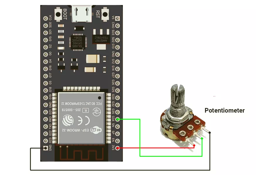
ESP32 Firmware Implementation
Let us write the code for this ADC serial plotter setup. It is very straightforward :
- Read the analog value
- Transmit it to the Serial plotter
- The serial plotter will plot these values
Code
//Hardware configuration
#define POT_PIN 15

void setup() {
  Serial.begin(115200);
  analogReadResolution(12);  // Set ADC resolution to 12-bit (default)
}

void loop() {
  // Read the analog values from pin 15
  int analogValue = analogRead(POT_PIN);

  // For the Serial Plotter, just print the values without any text
  Serial.println(analogValue);
  delay(100);  // Add a short delay to control the update rate
}
Code Explanation
analogRead(analogPin): reads ADC value.Serial.println: print ADC_value on the Serial monitor.
We are using the Arduino UNO development board and programming it using the Arduino IDE.
- Before uploading, make sure to select “Arduino UNO” as the board to ensure correct settings and compatibility.
Let’s do the hardware connection. We need a potentiometer to vary the input voltage signal.
Arduino UNO Circuit connection
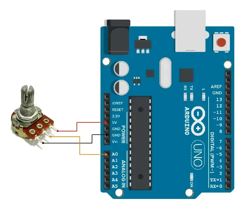
Arduino UNO Firmware Implementation
Let us write the code for this ADC serial plotter setup. It is very straightforward :
- Read the analog value
- Transmit it to the Serial plotter
- The serial plotter will plot these values
Code
void setup() {
  Serial.begin(9600);
}

void loop() {
  // Read the analog values from A0
  int analogValueA0 = analogRead(A0);

  // For the Serial Plotter, just print the values without any text
  Serial.println(analogValueA0);
  delay(100);  // Add a short delay to control the update rate
}
Code explanation
analogRead(analogPin): reads ADC value.Serial.println: print ADC_value on Serial monitor.
Output
The circuit is easy. Shown below
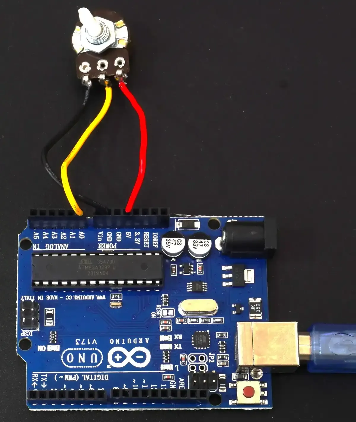
The output of increasing value is as above