8. LED Blink
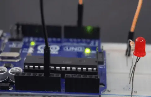
Let’s connect hardware first,
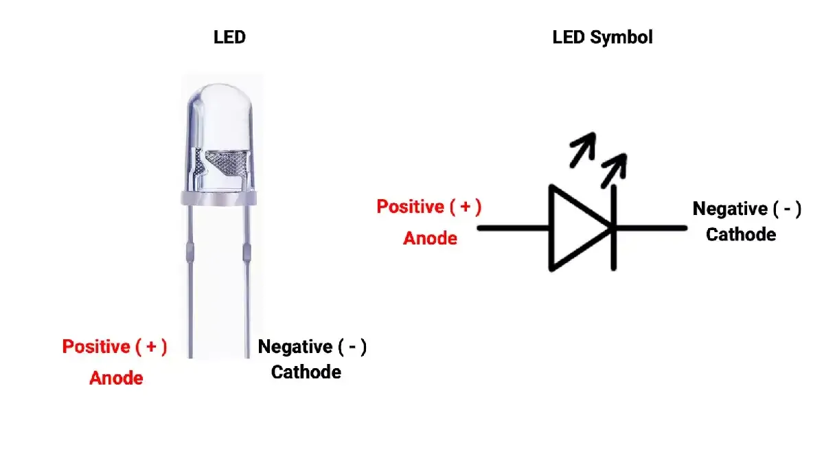
- Before connecting the LED, we need to understand its terminals properly.As we can see, there are 2 terminals, cathode (-ve) and anode (+ve).
- We must learn to identify LED terminals by observing them. If we observe properly, inside the LED, there is one terminal, which is flat (bigger size), which is always a cathode, and the remaining one is an anode.
- To turn ON the LED with proper brightness, it usually requires 10 to 20 mA of current through it. Exceeding the current above its higher limit will damage the LED.
- So, connecting the proper resistor is always important to avoid LED damage.
- Also, the LED drop voltage is around ~2 Volts, depending on LED color and specifications. It is always recommended to check the LED datasheet for LED current & drop-down voltage.
Note: "Always run LEDs below their maximum current to avoid damage. For example, if the max current is 25mA, aim for 10–15mA. This helps keep the LED cool and extends its life, especially since heat can reduce the safe current limit."
Calculating the Resistor Value
To ensure a 10 mA current through the LED, we need to select an appropriate resistor based on the supply voltage.
Case 1: 5V Supply
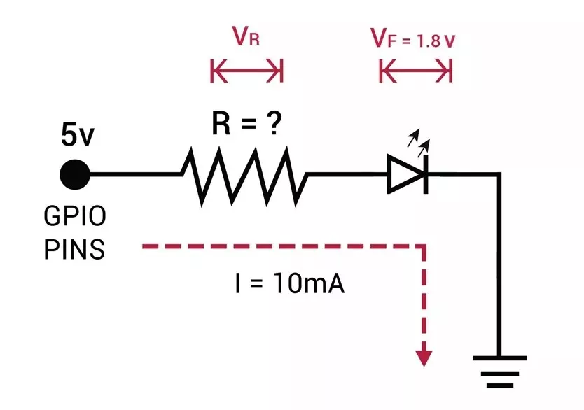
- LED forward voltage (Vf) = 1.8V (from datasheet)
- Voltage across resistor (VR) = Supply voltage – Vf = 5V – 1.8V = 3.2V
- Resistor value (R) = VR / I = 3.2V / 10 mA = 320 Ω
Standard resistor values near 320 Ω: 330 Ω or 300 Ω (whichever is available).
Similarly, Case 2: 3.3V Supply
- Voltage across resistor (VR) = 3.3V – 1.8V = 1.5V
- Resistor value (R) = 1.5V / 10 mA = 150 Ω
Standard resistor value: 150 Ω.
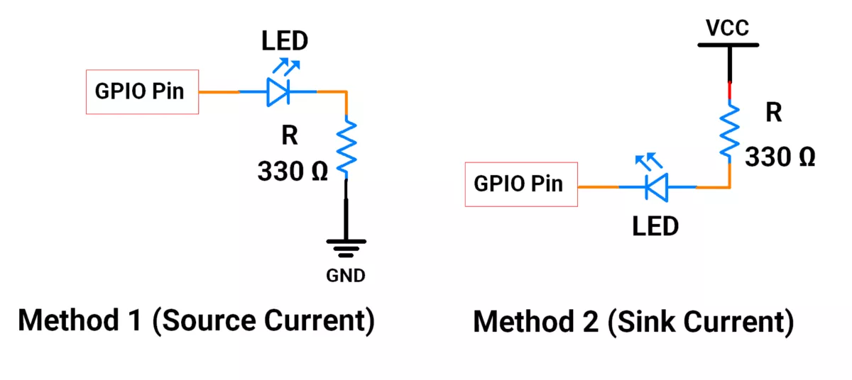
Methods of LED Connection with GPIO
The LED can be connected to a GPIO pin in two ways
Method 1: Sourcing Current from GPIO
- The anode is connected to the GPIO pin.
- The cathode is connected to ground via a resistor.
- The LED turns ON when the GPIO is HIGH.
Method 2: Sinking Current to GPIO
- The cathode is connected to the GPIO pin.
- The anode is connected to VCC via a resistor.
- The LED turns ON when the GPIO is LOW (acting as a sink to ground).
So, by selecting a proper resistor and connecting the LED correctly, we can implement the task.
Below are the solutions to the given task using different microcontrollers
- STM32
- ESP32
- Arduino UNO
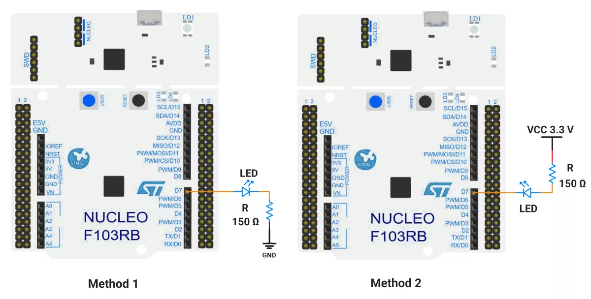
We’re using an STM32 NUCLEO-F103RB board, which runs at a 3.3V logic level.
Key Peripherals Used:
- GPIO: To connect the LED.
STM32 Hardware Connection
We can connect an LED to any GPIO. So, we will connect the LED to the GPIO pin PA8(D7).
Circuit Diagram
STM32 Firmware Implementation
Project Setup in STM32CubeIDE
- Create a Project
- Open STM32CubeIDE and start a new project, select the NUCLEO-F103RB board.
- Basic Configuration (via CubeMX inside CubeIDE)
- Clock: Keep the default internal oscillator (no custom changes needed).
- GPIO Configuration:
- LED: Set PA8 (D7) as GPIO Output Push-Pull in the Pinout view (via STM32CubeMX, built into CubeIDE).
- Code Generation
- CubeMX will automatically generate all the startup code, including:
HAL_Init()→ Initializes the HAL library.SystemClock_Config()→ Configures system clock.MX_GPIO_Init()→ Configures GPIO pins.
- This code sets up the hardware and prepares the project for firmware development, so we only need to add our application logic in the user code sections
- CubeMX will automatically generate all the startup code, including:
Code Snippets from main.c
GPIO Initialization
This configuration is generated inside MX_GPIO_Init(), where PA8 is set as a push-pull output with low speed, suitable for driving an LED.
// Inside MX_GPIO_Init()
GPIO_InitStruct.Pin = GPIO_PIN_8;
GPIO_InitStruct.Mode = GPIO_MODE_OUTPUT_PP;
GPIO_InitStruct.Speed = GPIO_SPEED_FREQ_LOW;
HAL_GPIO_Init(GPIOA, &GPIO_InitStruct);
Pin/LED Macros for Code Readability
These macros make your code more readable by giving meaningful names to the LED's port and pin.
#define LED_PORT GPIOA // GPIO port connected to the LED
#define LED_PIN GPIO_PIN_8 // GPIO pin connected to the LED
Main Firmware Logic
The LED state is controlled inside an infinite loop (while (1)) by using the HAL functions:
HAL_GPIO_WritePin()— to set or reset the output state of PA8.HAL_Delay()— to create a delay in milliseconds between state changes.
We can implement either of the two common wiring configurations to toggle the LED, depending on how the LED is connected to our hardware:
Method 1: Source Current Configuration
(Anode connected to PA8, cathode connected to GND through a resistor)
- LED ON: Set PA8 HIGH.
- LED OFF: Set PA8 LOW.
while (1) {
    // Turn LED ON
    HAL_GPIO_WritePin(LED_PORT, LED_PIN, GPIO_PIN_SET);
    HAL_Delay(400);  // Wait for 400 milliseconds
    // Turn LED OFF
    HAL_GPIO_WritePin(LED_PORT, LED_PIN, GPIO_PIN_RESET);
    HAL_Delay(800);  // Wait for 800 milliseconds
}
Method 2: Sink Current Configuration
(Cathode connected to PA8, anode connected to VCC through resistor)
- LED ON: Set PA8 LOW
- LED OFF: Set PA8 HIGH
while (1) {
    // Turn LED ON
    HAL_GPIO_WritePin(LED_PORT, LED_PIN, GPIO_PIN_RESET);
    HAL_Delay(400);  // Wait for 400 milliseconds
    // Turn LED OFF
    HAL_GPIO_WritePin(LED_PORT, LED_PIN, GPIO_PIN_SET);
    HAL_Delay(800);  // Wait for 800 milliseconds
}
Download Complete Project
The complete STM32CubeIDE project (including .ioc configuration, main.c, and HAL files) is available here:
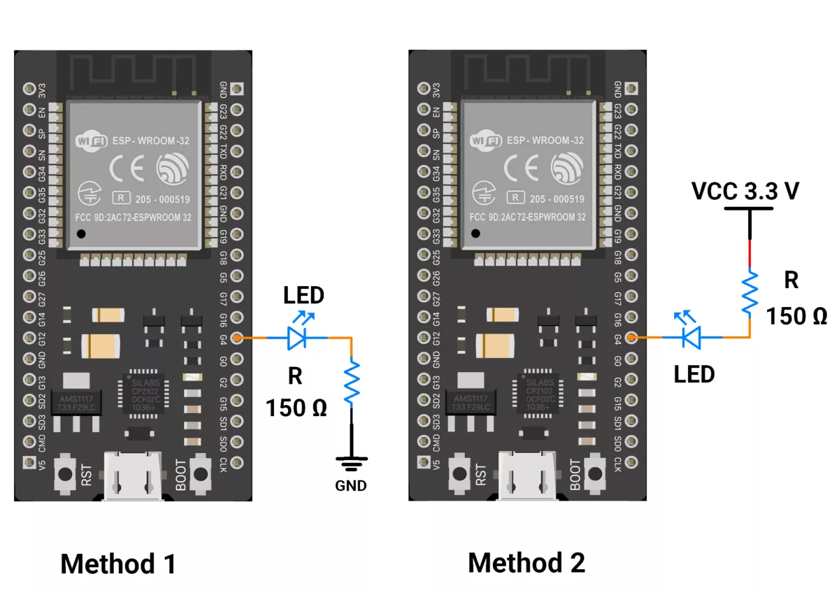
We are using the ESP32 DevKit v4 development board and programming it using the Arduino IDE.
- Before uploading, make sure to select “ESP32 Dev Module” as the board to ensure correct settings and compatibility.
The GPIO pins of the ESP32 provide a 3.3 V output.
To safely interface an LED and limit the current to 10 mA, we use a 150-ohm resistor, as calculated earlier.
We can connect an LED to any GPIO. So, we will connect the LED to the GPIO pin G4.
ESP32 Circuit Connections
ESP32 Firmware Implementation
We want to blink an LED such that it stays ON for 400 milliseconds and OFF for 800 milliseconds, repeating this cycle continuously.
Method 1: Source Current (Sourcing Mode)
- Turn ON the LED: Set GPIO pin HIGH
- Turn OFF the LED: Set GPIO pin LOW
Code for Method 1 (Source Current):
//Hardware configuration
#define LED_PIN 4

//Timing configuration
#define ON_TIME_MS 400
#define OFF_TIME_MS 800

//Initialize the hardware
void setup() {
  pinMode(LED_PIN, OUTPUT);
}

void loop() {
  digitalWrite(LED_PIN, HIGH);  // LED is turn on
  delay(ON_TIME_MS);            // wait for 400 millisecond
  digitalWrite(LED_PIN, LOW);   // LED is turn off
  delay(OFF_TIME_MS);           // wait for 800 milliseconds
}
Method 2: Sink Current (Sinking Mode)
- Turn ON the LED: Set GPIO pin LOW
- Turn OFF the LED: Set GPIO pin HIGH
Code for Method 2 (Sink Current):
//Hardware configuration
#define LED_PIN 4

//Timing configuration
#define ON_TIME_MS 400
#define OFF_TIME_MS 800

//Initialize the hardware
void setup() {
  pinMode(LED_PIN, OUTPUT);
}

void loop() {
  digitalWrite(LED_PIN, LOW);  // LED is turn on
  delay(ON_TIME_MS);            // wait for 400 millisecond
  digitalWrite(LED_PIN, HIGH);   // LED is turn off
  delay(OFF_TIME_MS);           // wait for 800 milliseconds
}
Code Explanation:
pinMode(led, OUTPUT);- In setup(), configures pin 4 as an output pin.digitalWrite()- To turn the LED on/off.delay()- Used to provide a delay in milliseconds.
Precaution
ESP32 GPIOs can source/sink up to 40mA, but are practically limited to ≤12mA to ensure reliability.
When sourcing current (GPIO set HIGH at 3.3V), the voltage drops with increasing current, indicating internal resistance (~20–40Ω).
E.g.
- When we withdraw 0mA GPIO voltage: ~3.3v
- When we withdraw 10mA, GPIO Voltage: ~2.95v
- When we withdraw 11mA, GPIO Voltage: ~2.8 v
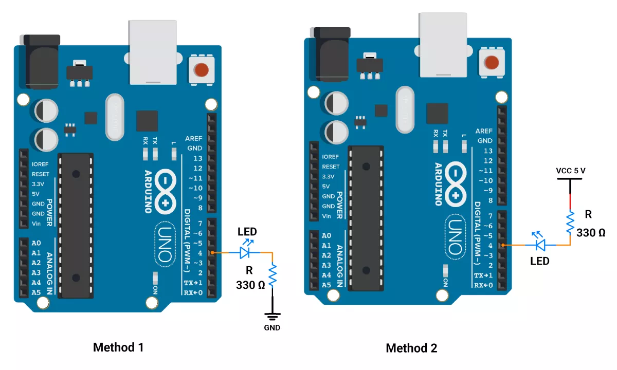
We are using the Arduino UNO development board and programming it using the Arduino IDE.
- Before uploading, make sure to select “Arduino UNO” as the board to ensure correct settings and compatibility.
The GPIO pins of the Arduino UNO provide a 5V output.
To safely interface an LED and limit the current to 10 mA, we use a 330-ohm resistor, as calculated earlier.
We can connect an LED to any GPIO. So, we will connect the LED to the GPIO pin 4.
Arduino UNO Circuit Connections
Arduino UNO Firmware Implementation
We want to blink an LED such that it stays ON for 400 milliseconds and OFF for 800 milliseconds, repeating this cycle continuously.
To control the LED, we toggle the GPIO pin by setting it either HIGH or LOW, depending on the wiring method used.
Method 1: Source Current (Sourcing Mode)
- Turn ON the LED: Set GPIO pin HIGH
- Turn OFF the LED: Set GPIO pin LOW
Code for Method 1 (Source Current):
const int led = 4;                //  LED is connected to the pin 4

void setup() {
 pinMode(led, OUTPUT);            // Set the LED pin as an output
}

void loop() {
  digitalWrite(led, HIGH);        // LED is turn ON
  delay(400);                     // waits for a 400 msec second
  digitalWrite(led, LOW);         // LED is turn OFF
  delay(800);                     // waits for a 800 msec second

}
Method 2: Sink Current (Sinking Mode)
- Turn ON the LED: Set GPIO pin LOW
- Turn OFF the LED: Set GPIO pin HIGH
Code for Method 2 (Sink Current):
const int led= 4;                //  LED connected pin 4
void setup() {
  pinMode(led, OUTPUT);          // Set the LED pin as an output
}
void loop() {
  digitalWrite(led, LOW);         // LED is turn ON
  delay(400);                          // waits for a 400 msec
  digitalWrite(led, HIGH);        // LED is turn OFF
  delay(800);                            // waits for a 800 msec
}
Code Explanation:
const int led = 4;- Declares a constant integer variable named "led" with value 4, meaning the LED is connected to digital pin 4.pinMode(led, OUTPUT);- In setup(), configures pin 4 as an output pin.- Both use
digitalWrite()to turn the LED on/off anddelay()to create timing. - Method 1 Behaviour:
- The LED turns ON (HIGH) for 400ms, then OFF (LOW) for 800ms
- Method 2 Behaviour:
- The LED turns ON (LOW) for 400ms, then OFF (HIGH) for 800ms
Precautions:
- However, we know that the source and sink current of the GPIO is 40mA. However, we should not exceed the current of 20mA practically.
- Also, when we withdraw current through GPIO HIGH, i.e., 5 volts, its voltage drops with respect to the current drawn.
- I.e. when we withdraw 0mA GPIO voltage: 4.98v
- When we withdraw 10mA, GPIO Voltage: 4.75V
- When we withdraw 20mA, GPIO Voltage: 4.50V
This shows that GPIO has an internal resistance of 25 ohms.
Output