39. GPIO Status LED Selection
Aarav is designing a microcontroller board and wants to connect a status LED directly to a 3.3V GPIO pin.
The LED will show simple signals like heartbeat, fault, or system ON.
To avoid overloading the GPIO, he wants the LED to work at low current but still remain clearly visible.
He decides to use a green, 0603 SMD LED.
Help him select a suitable LED from DigiKey.
Make sure it is good for low-current GPIO drive and works reliably in industrial temperatures.
Visit DigiKey's LEDs category and find a suitable part.
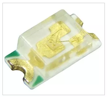
What is an LED?
- A Light Emitting Diode is a PN‑junction device that emits photons when forward‑biased (electroluminescence).
- It’s optimized for light output, not rectification.
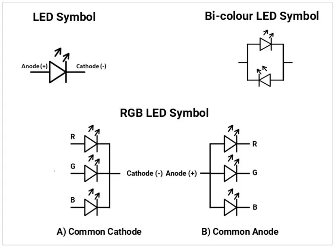
LED and connections diagram:
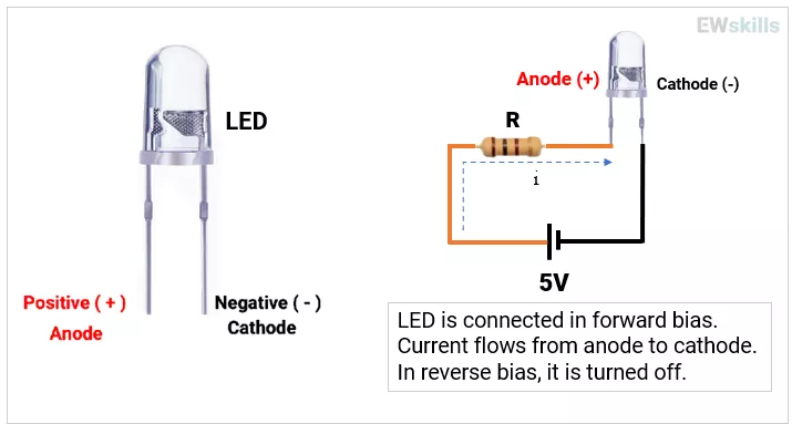
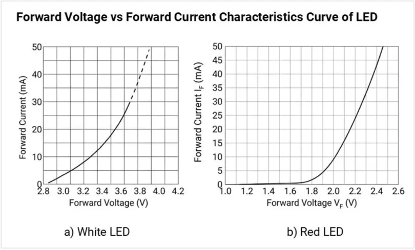
- Conduction: Turns ON when LED’s forward voltage (VF) is reached; current must be limited externally or by a driver.
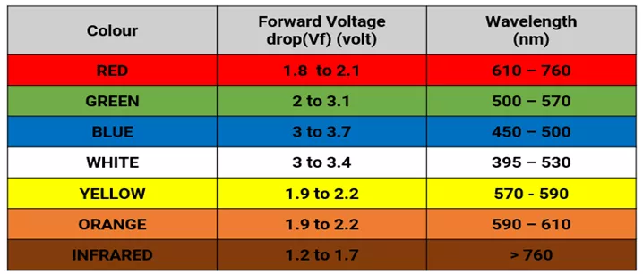
- VF ranges (typical):
- Red/IR ~1.6–2.0 V,
- Green/Yellow ~2.0–2.4 V,
- Blue/White ~2.8–3.6 V.
LED schematic symbol (fixed, RGB, bicolor)
IV curve (VF vs IF) from datasheet for red & white LEDs
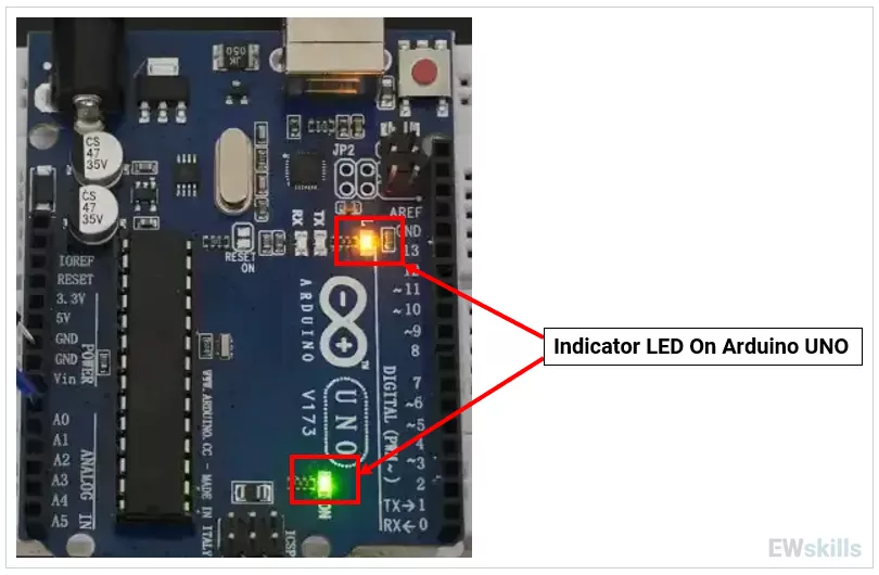
Practical Use Cases
1) Status indicators (power, fault, communication).
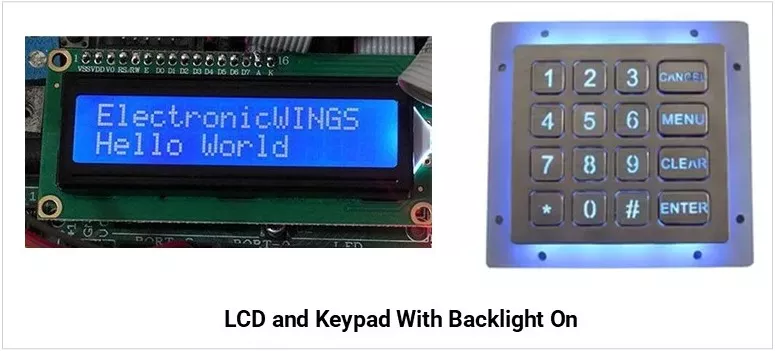
2) Backlighting (LCDs, keypads).
3) IR communication (TV remotes, proximity).
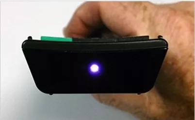
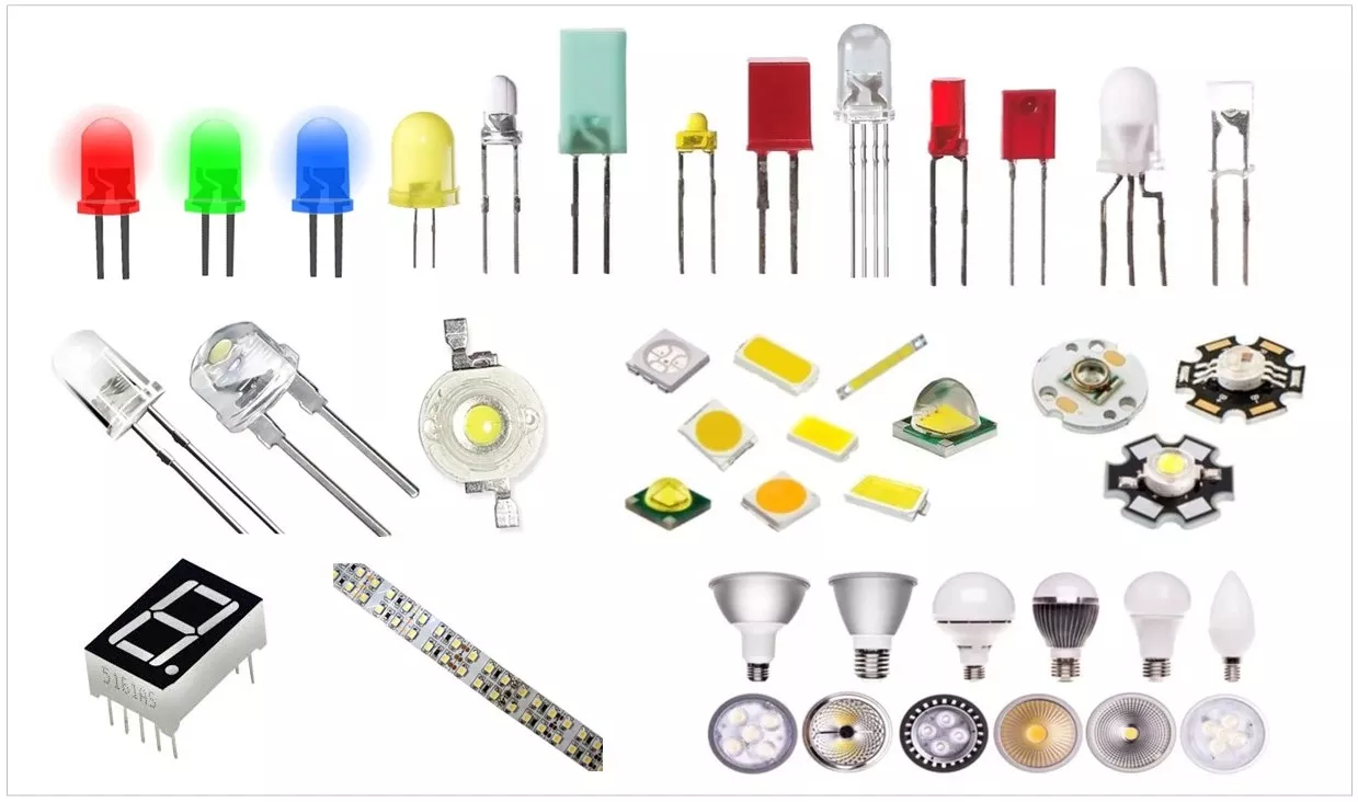
Types of LEDs
| Type | Image | Description |
|---|---|---|
| Through-Hole LEDs | 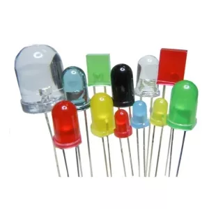 |
|
| Surface Mount LEDs (SMD) | 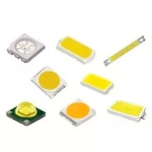 |
|
| UV LEDs | 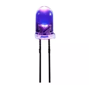 |
|
| High-Power LEDs | 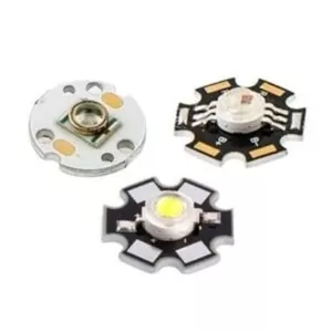 |
|
| RGB LEDs | 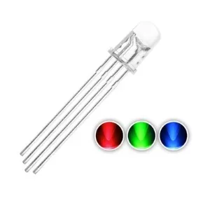 |
|
| Bi-Colour LEDs | 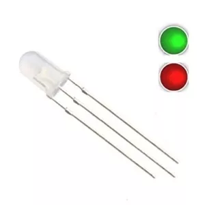 |
|
Key Specifications
- VF (Forward Voltage): Voltage across LED at a given IF; varies with LED color (material bandgap), applied current, and temperature.

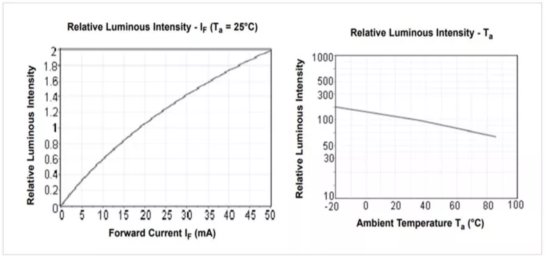
- IF (Forward Current): It determines LED brightness and heating.
It must always be kept below the Absolute Maximum Rating to avoid damage.
Example: For a 20 mA LED, the recommended IF might be 10–15 mA for long life. - IFP (Peak/Pulse Current): Short pulses allowed under specific duty cycles.
Typical limit of duty cycle: ≤ 1%–10%, depending on LED. - Luminous intensity (mcd) vs Luminous flux (lm):
- Luminous intensity is the amount of light emitted in a specific direction. Unit: mcd (millicandela).
- Luminous flux is the total quantity of visible light emitted in all directions. Unit: lumen (lm).
- Design Rule: For indicators, use mcd (spot brightness), for lighting use lm (total illumination).
- Viewing angle (°): Beam spread; a narrower beam looks brighter head‑on.
- Wavelength (nm) / Dominant wavelength: Color accuracy for mono color LEDs.
- Correlated Color Temperature (CCT): CCT describes the apparent color of white light from an LED, expressed in Kelvin (K).
- Low CCT → Warm, relaxing light (residential, decorative).
- High CCT → Cool, stimulating light (offices, hospitals, outdoor, industrial).
- Color Rendering Index (CRI) – color accuracy for illumination.
- Thermal resistance (RθJA/RθJB/RθJS): Junction‑to‑ambient/board/solder; lower is better.
- Power dissipation & derating: Max heat the LED can dissipate; check derating vs temperature.
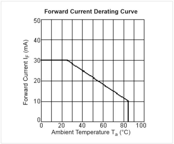
Derating Curve : (Understand the curve carefully- although max current rating is 30mA- it declines over the Temperature rise. While operating in High ambient temperature- need to consider the curve)
- Reverse voltage (VR): Often very low; avoid reverse bias or provide a protection diode.
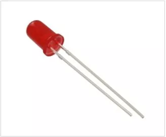
Example Würth Elektronik 151051RS11000 (WL-TMRC series) 5mm red LED specifications:
| Specification | Value |
|---|---|
| VF (Forward Voltage) | Typical: 2.1 V; Maximum: 2.5 V (at IF = 20mA) |
| IF (Forward Current) | Absolute Maximum: 30 mA; Test/Recommended: 20 mA |
| IFP (Peak/Pulse Current) | 100 mA (Condition: 1/10 duty cycle @ 1 kHz) |
| Luminous Intensity (mcd) | 30 mcd (Typical at 20 mA) |
| Luminous Flux (lm) | Not specified (Standard indicator; use 30 mcd for spot brightness) |
| Viewing Angle (°) | 60° |
| Wavelength (nm) | Dominant: 645 nm; Peak: 650 nm |
| Power Dissipation | 75 mW |
| Derating Curve | Continuous current starts at 20 mA and begins to decline linearly after ~55°C ambient temperature (TA) |
| Reverse Voltage (VR) | 5 V (Maximum) |
Packages & Footprints (what to recognize on a PCB)
| Package Type | Image | Physical Features & Recognition | Common Package / Case |
|---|---|---|---|
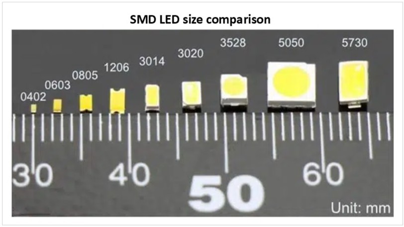
| Standard SMD | 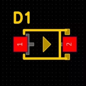 | Tiny rectangular blocks. Look for side pads (terminations) and a clear/yellow top emitter window. Often features a polarity mark (green line or notched corner). | 0402, 0603, 0805, 1206 |
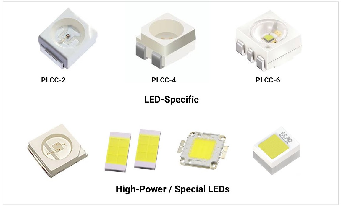
| PLCC (Plastic Leaded Chip Carrier) | 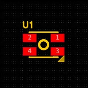 | Larger, square plastic bodies with legs folded under or along the sides. Usually has a notched corner to indicate the Cathode. | PLCC-2, PLCC-4 |
| High-Power SMD | 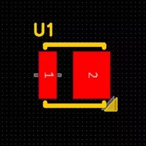 | Square ceramic or plastic base. Look for a large central thermal pad underneath the chip to transfer heat to the PCB. | 3535, 5050, 7070 |
| COB (Chip on Board[SS5] ) | 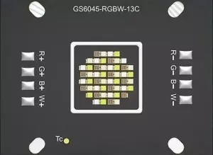 | A large yellow or orange phosphor area directly on a metal substrate. Usually mounted on a Metal Core PCB (MCPCB) with screw holes. | Circular or Square COB modules |
| Through-Hole | 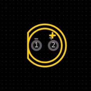 | Vertical cylinders with domed or diffused lenses. Identified on PCBs by two circular pads and a silkscreen "flat side" indicating the cathode. | 3 mm (T-1), 5 mm (T-1¾) |
Through Hole Types
| Type | Description | Applications | Image |
|---|---|---|---|
| Radial LED | Leads come out from the bottom of the LED package (most common 3 mm, 5 mm, 10 mm LEDs). | General indicators, panel mount, displays. | 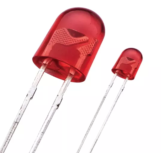 |
| Axial LED | Leads extend straight out from opposite sides of the package (like resistors/axial diodes). | Used in signage, backlighting, or tight horizontal layouts. | 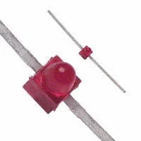 |
SMD LED Package Classification
| Category | Imperial Code | Metric Code | Dimensions (mm) | Typical Power |
|---|---|---|---|---|
| Standard EIA Sizes | 0201 | 0603 | 0.6 × 0.3 | <0.01 W (indicator only) |
| 0402 | 1005 | 1.0 × 0.5 | <0.02 W | |
| 0603 | 1608 | 1.6 × 0.8 | 0.02–0.05 W | |
| 0805 | 2012 | 2.0 × 1.25 | 0.05–0.1 W | |
| 1206 | 3216 | 3.2 × 1.6 | 0.05–0.1 W | |
| 1210 | 3225 | 3.2 × 2.5 | 0.1–0.2 W | |
| 3528 | 3528 | 3.5 × 2.8 | 0.1–0.2 W | |
| 2835 | 2835 | 2.8 × 3.5 | 0.2–0.5 W | |
| 3014 | 3014 | 3.0 × 1.4 | 0.05–0.2 W | |
| 3020 | 3020 | 3.0 × 2.0 | 0.05–0.2 W | |
| 3030 | 3030 | 3.0 × 3.0 | 0.5–1.0 W | |
| 4014 | 4014 | 4.0 × 1.4 | 0.2–0.5 W | |
| 5050 | 5050 | 5.0 × 5.0 | 0.2–0.5 W per die (RGB = 3 dies → up to 1.5 W) | |
| 5630 | 5630 | 5.6 × 3.0 | 0.5–1.0 W | |
| 5730 | 5730 | 5.7 × 3.0 | 0.5–1.0 W | |
| 7070 | 7070 | 7.0 × 7.0 | 2.0–3.0 W+ |
| Category | Metric Code | Dimensions (mm) | Typical Power |
|---|---|---|---|
| LED-Specific | PLCC-2 | ~3.5 × 2.8 | 0.05–0.2 W |
| PLCC-4 | ~5.0 × 5.0 | 0.2–0.6 W (RGB total) | |
| PLCC-6 | ~5.0 × 5.0 | 0.3–0.9 W (RGB total) | |
| High-Power / Special | 3535 | 3.5 × 3.5 | 1.0–3.0 W |
| 7575 | 7.5 × 7.5 | 3.0–5.0 W | |
| CSP | ≈1–2 mm | 0.1–1.0 W | |
| COB | Multi-die arrays | 5–50+ W | |
| Ceramic SMD | Varies | 1–5 W typical |
LED Polarity identification and testing.
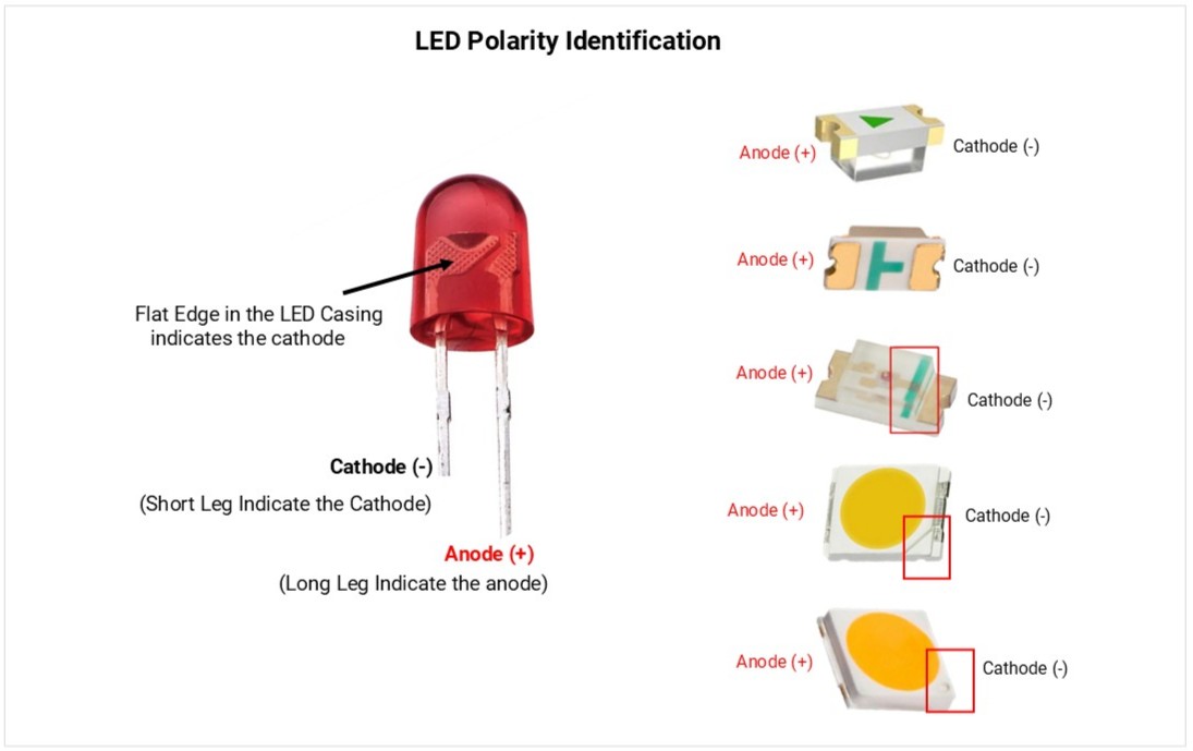
LEDs are polarized; current only flows from Anode (+) to Cathode (-).
1. Visual Identification
- Anode (+): Longer lead; round casing side.
- Cathode (-): Shorter lead; flat edge on the casing; internal "anvil" (larger metal part).
- SMD (Surface Mount): A printed line, dot, or notch indicates the Cathode.
2. Multimeter Testing (Diode Mode)
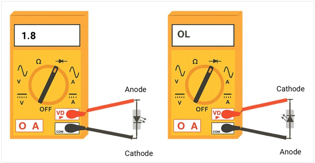
To verify polarity or health, touch the probes to the leads:
| Test Type | Connection | Result | Meaning |
|---|---|---|---|
| Forward Bias | Red (+) to Anode / Black (-) to Cathode | 1.7V – 3.0V | Functional; LED may glow. |
| Reverse Bias | Red (+) to Cathode / Black (-) to Anode | OL | Correct; blocking current. |
3. Diagnostic Results
- Healthy: Shows voltage in forward bias and OL in reverse.
- Faulty (Open): Shows OL in both directions (internal break).
- Faulty (Short): Shows 0.00 in both directions (internal fuse).
Standard Voltage & Wavelength
- Indicator LED’s Forword current (IF): 2–20 mA (many are visible at 1–2 mA with high‑efficiency types).
- High‑power LED’s Forword current (IF): ~350 mA (1 W), 700 mA (3 W), 1 A+ (5 W+).
- Common wavelengths: IR 850/940 nm; Red 620–630 nm; Green 520–530 nm; Blue 460–470 nm; UV 365–400 nm.
- Common packages: Through hole, 0805/1206 (indicator), 2835/3030/3535/5050/7070 (power/RGB), COB modules.
How to Select an LED (step‑by‑step)
- Understand the application: Indicator? Backlight? Illumination? IR/UV? RGB effects?
- Pick color/wavelength or CCT/CRI:
- Indicators: choose color for contrast; use narrow beam for bright “dot”.
- Illumination: choose CCT (e.g., 3000 K warm) and CRI (≥80 or ≥90 for color‑critical).
- Set brightness target:
- Select LEDs by reviewing datasheets for high luminous intensity (millicandela/mcd) and proper viewing angles.
- Choose electrical approach: Resistor (simple), constant‑current driver (recommended for power/RGB/precision).
- Budget voltage/current: Verify supply headroom for max IF (Forward current) and VF (Forward Voltage). consider ambient temperature.
- Thermal plan: Estimate power → Rθ path → heatsink/copper/MCPCB.
- Package & assembly: THT vs SMD; reflow vs hand solder; lens/mechanical constraints.
- Reliability: Check derating, ESD, MSL, sulfur resistance (for environments with sulfides).
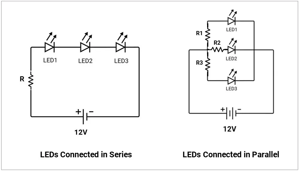
Series / Parallel & Arrays (don’t fry LEDs)
- Series preferred for equal current through each LED.
- Parallel pitfalls: Current hogging due to VF mismatch → one LED overheats.
- If you must parallel, give each LED its own resistor or use current-sharing circuitry.
- Matrix/multiplexing: Consider duty cycle; increase peak current within IFP limits to maintain average brightness; watch eye‑safety with IR/UV.
Common Failure Modes & Field Issues
- Overcurrent/overheat: Open circuit or dark/weak LED; lumen depreciation (L70 reached early).
- ESD damage: Partial shorts/leakage; dim or intermittent behavior.
- Color shift: Phosphor aging in white LEDs; visible tint change.
- Sulfur corrosion: Blackening of silver‑plated leadframes (harsh environments).
- Moisture popcorning: Cracks after reflow if MSL not respected.
- Optics degradation: Lens yellowing/clouding with heat/UV.
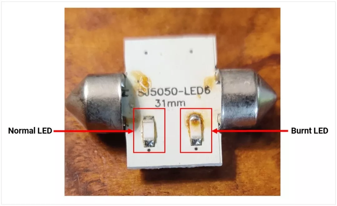
Normal vs Burnt LED Image:
LED Insights
- Luminous intensity vs viewing angle
- Luminous intensity (mcd) indicates how bright an LED appears in a specific direction
- LEDs with a narrow viewing angle:
- Light is more focused
- Appears brighter (higher mcd)
- LEDs with a wide viewing angle:
- Light spreads out more
- Appears less bright
- High mcd LEDs are preferred for indicators for better long-distance visibility
- Wavelength & color
- LED color is defined by its wavelength (in nm)
- Infrared: ~760 nm+ (used in remotes, cameras)
- Visible: ~450–760 nm (blue to red)
- UV: ~365–400 nm
- Narrow spectral output results in a purer and more saturated color
- Color temperature (CCT) – white LEDs
- Measured in Kelvin (K), indicates light tone
- 2700–3000 K: Warm (yellowish, home use)
- 3500–4100 K: Neutral (offices)
- 5000–6500 K: Cool (industrial, hospitals)
- High temperature or current can shift color (usually toward blue)
- Hue (color type)
- Represents the actual color, linked to wavelength
- Expressed as an angle (0°–360°):
- Red: 0°
- Green: 120°
- Blue: 240°
- RGB mixing can generate any color
- Saturation (color purity)
- Defines how pure or washed-out a color is
- 100% → Pure, vivid color
- 0% → White/gray
- Adding more colors reduces saturation
- Intensity (brightness)
- Represents total light output
- Controlled using PWM (Pulse Width Modulation):
- 0% → Off
- 100% → Maximum brightness
- Allows brightness control without affecting color
- HSI vs RGB (for programming)
- Hue: Sets color
- Saturation: Controls color purity
- Intensity: Controls brightness (via PWM)
- HSI is more intuitive compared to raw RGB values