75. I2C Slave with Sleep Mode
Build a power-efficient I2C-based Slave using a microcontroller with the following functionalities:
- The I2C slave is in power-saving mode to save power.
- A push button switch is connected to the I2C master. After pressing it, the I2C master must wake up the slave via I2C.
- A potentiometer is connected to the slave. Upon waking up, the slave reads its ADC value, sends it to the master, and then goes back to power-saving mode.
- The slave responds to every switch press by repeating this process.
NOTE: Use an I2C-supported microcontroller as the I2C master.
Arduino UNO I2C Master Sample Code
Below is the sample code for Arduino UNO as a Master that receives ADC values from the I2C slave and prints on the serial terminal (e.g., Putty, Arduino IDE).
This code can be used for demonstration.
#include <Wire.h>

#define SWITCH_PIN 3  // Pin connected to the switch

unsigned long debounce_delay = 50;     // Debounce delay in milliseconds
int last_button_state = 1;             // Previous button state (1: not pressed, 0: pressed)
int current_button_state = 1;          // Current button state
unsigned long last_debounce_time = 0;  // Timestamp of the last button state change

void setup() {
  Serial.begin(115200);                                                     // Initialize serial communication
  pinMode(SWITCH_PIN, INPUT_PULLUP);                                        // Set SWITCH_PIN as input with internal pull-up resistor
  Serial.println("Master is ready");                                        // Print setup message
  Serial.println("Press the pushbutton to read the ADC value form slave");  // Print setup message
  Wire.begin();                                                             // Join I2C bus as Master
}

void loop() {
  // Check if the switch is pressed with debounce handling
  if (is_debounced_press(SWITCH_PIN)) {
    // Request 2 bytes from Slave with address 0x08 (ADC value)
    Wire.requestFrom(0x08, 2);

    uint16_t receivedData = 0;  // Variable to store the received data
    if (Wire.available() >= 2) {
      // Read the low and high bytes of the received data
      uint8_t lowByte = Wire.read();   // Read the low byte
      uint8_t highByte = Wire.read();  // Read the high byte

      // Combine the high and low byte into a 16-bit value
      receivedData = (highByte << 8) | lowByte;  // Combine the two bytes

      // Print the received ADC value from the slave
      Serial.print("Received ADC value from slave: ");
      Serial.println(receivedData);
    } else {
      Serial.println("Read failed !!!");
    }
  }
}

// Function to handle debouncing of the button press
bool is_debounced_press(int button_pin) {
  int reading = digitalRead(button_pin);  // Read the current state of the button

  // If the button state has changed, reset the debounce timer
  if (reading != last_button_state) {
    last_debounce_time = millis();  // Update the last debounce time
  }
  last_button_state = reading;  // Save the current button state for the next loop

  // If the button state is stable for more than the debounce delay
  if ((millis() - last_debounce_time) > debounce_delay) {
    // If the button state has changed after the debounce delay
    if (reading != current_button_state) {
      current_button_state = reading;

      // Return true if the button is pressed (LOW state)
      if (current_button_state == 0) {
        return true;  // Valid press detected
      }
    }
  }

  return false;  // No valid press detected (debounced press)
}
Sleep mode
Sleep mode in a microcontroller is a power-saving state where the CPU stops, but selected peripherals can keep running.
They reduce power consumption while maintaining the ability to wake up from wake sources
Why We Need Sleep Mode:
Sleep mode is needed in microcontrollers to save power when the CPU is idle. It extends battery life.
Sleep Modes in ATmega328P
ATmega328P supports six sleep modes:
- Idle – CPU stops; peripherals (Timers, USART, etc.) keep running. This mode has the fastest wake-up.
Wake-up Sources: Any enabled interrupt, such as from a Timer, USART, or Pin Change, can wake the CPU. - ADC Noise Reduction – CPU and I/O stops; ADC runs with less noise.
Wake-up Sources: ADC interrupt, external interrupt, watchdog - Power-down – Most peripherals are turned off; This consumes the lowest power.
Wake-up Sources: External interrupt (INT0/1, Pin Change), watchdog time - Power-save – Like Power-down, but Timer2 runs asynchronously for timed wake-ups.
Wake-up Sources: Timer2 overflow, external interrupt, watchdog - Standby – Like Power-down, with faster wake-up using the external oscillator.
Wake-up Sources: External interrupt, watchdog - Extended Standby – Combines Power-save and Standby for both Timer2 and fast wake-up.
Wake-up Sources: Timer2, external interrupt, watchdog
Wake-Up Sources:
- External interrupts (INT0, INT1) – Triggered by a change (edge or level) on specific external pins.
- Pin change interrupts – Triggered by any logic change on enabled I/O pins.
- Watchdog Timer interrupt – Fires after a set timeout, useful for periodic wake-ups.
- Timer overflow/compare match (e.g., Timer2) – Wakes the MCU when a timer reaches a set value; works in async mode for deeper sleep.
- Communication Events – Wakes the MCU when a communication event occurs ( byte received, address detected).
- Analog comparator interrupt – Wakes the MCU when the voltage comparison between two inputs matches.
Registers:
In AVR microcontrollers (like ATmega328P), sleep modes are controlled using the SMCR (Sleep Mode Control Register). This 8-bit register allows you to select and enable sleep behavior.
- The SM[2:0] bits (bits 2:0) select the sleep mode (e.g., Idle, Power-down)
- The SE bit (bit 7) enables the sleep feature; the device enters sleep when the SLEEP instruction is executed.
- The SMCR register must be set before entering sleep, and interrupts must be configured properly for wake-up.
This register is responsible for managing power modes in AVR microcontrollers.
NOTE: Similar types of registers are present in other microcontrollers for controlling the sleep modes. More advanced registers like SYST_CSR in ARM manage sleep and system tick behaviour, offering finer control.
Driver setup (AVR Atmega328P)
To set up sleep modes in AVR microcontrollers like the ATmega328P, follow these steps:
- Configure the Sleep Mode: Set the desired sleep mode using the SMCR (Sleep Mode Control Register) by selecting the mode via the SM[2:0] bits (e.g., Idle, Power-down).
- Enable Sleep: Set the SE (Sleep Enable) bit in the SMCR register to allow the microcontroller to enter sleep.
- Execute Sleep: Use the SLEEP instruction to put the microcontroller into the selected sleep mode.
- Interrupts: Ensure necessary interrupts are enabled to wake up the device, such as external interrupts or a watchdog timer.
- Optional - Disable Unused Peripherals: To save more power, disable unused peripherals by configuring bits in the PRR (Power Reduction Register).
- Optional - Disable Sleep After Wake-up: Clear the SE bit after wake-up to prevent accidental re-entry into sleep mode.
The microcontroller remains in sleep until a valid interrupt or event triggers a wake-up.
Arduino Functions
| Type | Name | Description |
|---|---|---|
Include Headers
| <avr/sleep.h> | Sleep mode control functions. |
<avr/power.h> | Power reduction functions for peripherals. | |
Functions
| set_sleep_mode(mode) | Sets the desired sleep mode (e.g., SLEEP_MODE_PWR_DOWN). |
sleep_enable() | Enables sleep mode. | |
sleep_mode() | Puts MCU to sleep. | |
sleep_disable() | (Optional) Disables sleep after waking. |
Power.h functions
Library: #include <avr/power.h>
| Function | Description |
|---|---|
power_adc_disable() / power_adc_enable() | Disable/enable ADC. |
power_timer0_disable() / power_timer0_enable() | Disable/enable Timer0. |
power_timer1_disable() / power_timer1_enable() | Disable/enable Timer1. |
power_timer2_disable() / power_timer2_enable() | Disable/enable Timer2. |
power_twi_disable() / power_twi_enable() | Disable/enable I2C (TWI). |
power_spi_disable() / power_spi_enable() | Disable/enable SPI. |
power_usart0_disable() / power_usart0_enable() | Disable/enable USART. |
sleep_bod_disable() | Disables BOD before sleep |
Example Code:
1. Example of using Power-down sleep mode with external interrupt wake-up to toggle an LED on Arduino UNO.
Code
#include <avr/sleep.h>
#include <avr/interrupt.h>

#define LED 12

volatile bool wakeFlag = false;

void setup() {
  pinMode(2, INPUT_PULLUP);       // INT0
  pinMode(LED, OUTPUT);            // LED pin

  attachInterrupt(digitalPinToInterrupt(2), wakeISR, LOW);

  set_sleep_mode(SLEEP_MODE_PWR_DOWN);
  sleep_enable();
  sei();
}

void loop() {
  sleep_mode();                   // MCU sleeps here

  // After waking up
  if (wakeFlag) {
    wakeFlag = false;
    digitalWrite(LED, !digitalRead(LED)); // Toggle LED
  }

  // Optional delay to avoid bouncing issues
  delay(50);
}

void wakeISR() {
  wakeFlag = true; // Set flag to handle logic after wake
}
2. Code to blink the LED three times when the Arduino wakes up. The Arduino goes to sleep and wakes up every 8 seconds using the Watchdog Timer (WDT) as the interrupt-based wake-up source.
Code
#include <avr/sleep.h>
#include <avr/wdt.h>
const int ledPin = 13;

void setup() {
  pinMode(ledPin, OUTPUT);

  // Disable ADC to save power
  ADCSRA &= ~(1 << ADEN);

  // Setup Watchdog Timer
  setupWatchdogTimer();

  // Enable sleep mode
  set_sleep_mode(SLEEP_MODE_PWR_DOWN);
  sleep_enable();

  // Ensure interrupts are globally enabled
  sei();
}


void loop() {
  // Blink the LED three times on wakeup
  for (int i = 0; i < 3; i++) {
    digitalWrite(ledPin, HIGH);
    delay(200);
    digitalWrite(ledPin, LOW);
    delay(200);
  }

  // Go to sleep again
  sleep_mode();
}


// WDT interrupt service routine
ISR(WDT_vect) {
  // This interrupt wakes the MCU from sleep
}


void setupWatchdogTimer() {
  // Clear WDRF in MCUSR
  MCUSR &= ~(1 << WDRF);

  // Set up WDT for interrupt mode only, every 8 seconds
  // Step 1: Enable configuration change
  WDTCSR |= (1 << WDCE) | (1 << WDE);

  // Step 2: Set for interrupt mode, 8s timeout
  WDTCSR = (1 << WDIE) | (1 << WDP3) | (1 << WDP0);  // 8s
}
Power Saving Techniques
To reduce power consumption in microcontrollers like the ATmega328P, several effective techniques can be used:
- Use deep sleep modes (e.g., Power-down mode) to shut down the CPU and most peripherals when not in use.
- Disable unused peripherals such as ADC, SPI, I2C, or timers to prevent unnecessary power draw.
- Reduce the clock frequency to lower the overall current consumption during active operation.
- Disable the Brown-Out Detector (BOD) in sleep mode for additional savings, as it consumes power.
- Keep GPIOs in known logic states (avoid floating pins) to prevent leakage currents.
In ATmega328P, the Power Reduction Register (PRR) allows selective disabling of clock signals to specific peripherals. Turning off modules like ADC, USART, or Timers through PRR is especially useful in sleep modes, where it can significantly extend battery life.
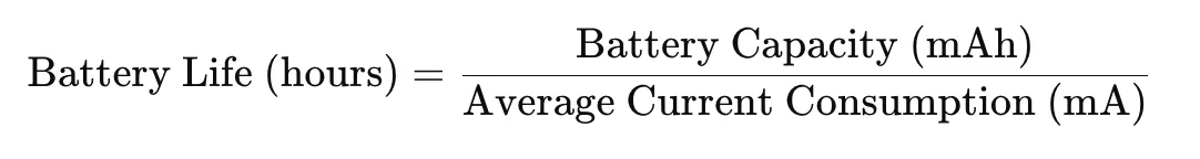
Calculating the Battery Life
- To calculate battery life from the average current in a microcontroller, use the formula:
- Average current is the total current drawn by the microcontroller over time, accounting for both active and sleep modes. To calculate the average current:

where:
- Active Current is the current drawn during the active mode (e.g., while performing tasks).
- Sleep Current is the current drawn during sleep mode (e.g., low-power or idle states).
- Active Time is the duration spent in the active mode.
- Sleep Time is the duration spent in sleep mode.
- Total Time is the total duration of one complete cycle (Active Time + Sleep Time).
Example:
Here’s an example of estimating battery life based on given conditions:
- Battery capacity = 2000 mAh
- Active Current = 20 mA (current during active mode)
- Sleep Current = 1 mA (current during sleep mode)
- Active Time = 5 seconds
- Sleep Time = 55 seconds
- Total Time = 60 seconds (1 minute)
First, calculate the average current:
Average Current = (20 * 5 / 60) + (1 * 55 / 60) = 2.58 mA
Then, estimate the battery life:
Battery Life = 2000 mAh / 2.58 mA ≈ 775.1 hours ≈ 32.29 days
This means the battery will last approximately 32.29 days with the given usage pattern.