12. Implement a 4-bit binary counter
Let's first understand the 4-bit binary counter before implementing it.
- A 4-bit binary counter can count up to 2^4=16 states, ranging from 0x00 to 0x0F. The table below shows the counts for the counter.
| Counter Value in Decimal | Counter Value in Hexadecimal | Binary Count of Counter |
|---|---|---|
| 0 | 0X00 | 0000 |
| 1 | 0X01 | 0001 |
| 2 | 0X02 | 0010 |
| 3 | 0X03 | 0011 |
| 4 | 0X04 | 0100 |
| 5 | 0X05 | 0101 |
| 6 | 0X06 | 0110 |
| 7 | 0X07 | 0111 |
| 8 | 0X08 | 1000 |
| 9 | 0X09 | 1001 |
| 10 | 0x0A | 1010 |
| 11 | 0X0B | 1011 |
| 12 | 0X0C | 1100 |
| 13 | 0X0D | 1101 |
| 14 | 0X0E | 1110 |
| 15 | 0X0F | 1111 |
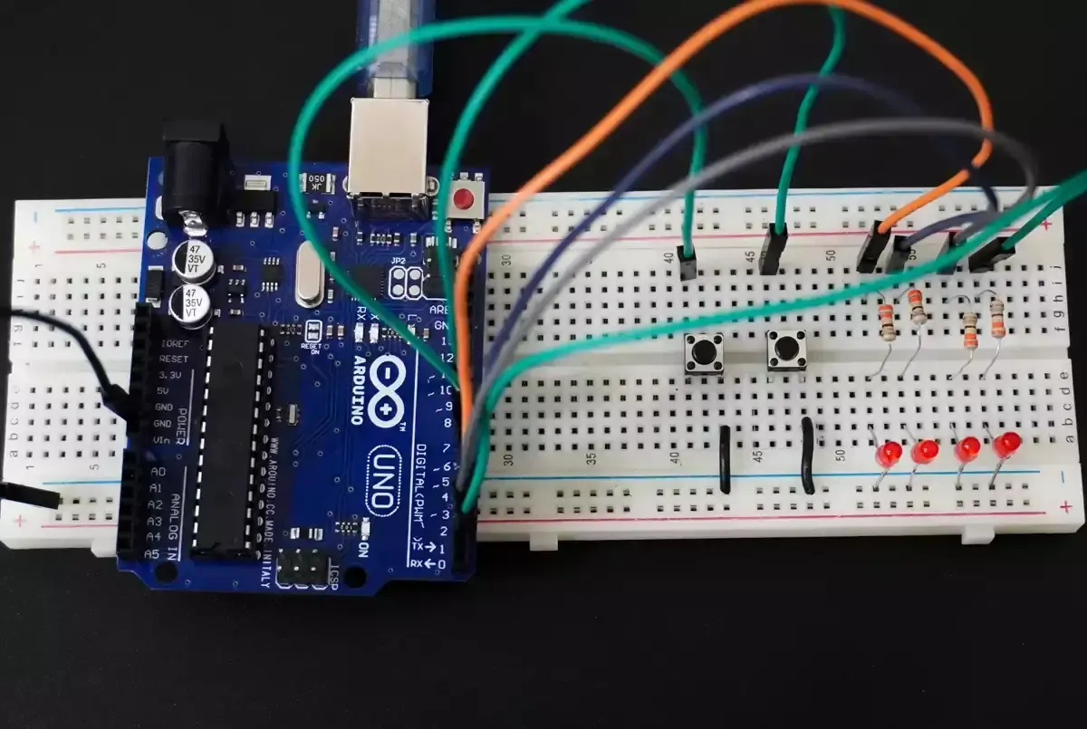
Let's connect hardware,
We need to use a proper resistor for each LED to limit the current flowing through them to 10mA.
Calculating the Resistor Value
To ensure a 10 mA current through the LED, we need to select an appropriate resistor based on the supply voltage.
Case 1: 5V Supply
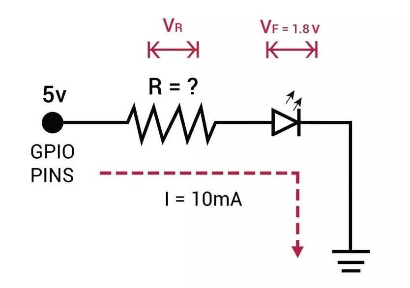
- LED forward voltage (Vf) = 1.8V (from datasheet)
- Voltage across resistor (VR) = Supply voltage – Vf = 5V – 1.8V = 3.2V
- Resistor value (R) = VR / I = 3.2V / 10 mA = 320 Ω
Standard resistor values near 320 Ω: 330 Ω or 300 Ω (whichever is available).
Similarly, Case 2: 3.3V Supply
- Voltage across resistor (VR) = 3.3V – 1.8V = 1.5V
- Resistor value (R) = 1.5V / 10 mA = 150 Ω
Standard resistor value: 150 Ω.
Interfacing the push button switch:
To change the LED blinking pattern, use a push-button switch. When connecting the switch, ensure it correctly provides GPIO levels (LOW and HIGH). For reliable detection of voltage levels, use either a pull-up or pull-down resistor configuration.
- Case 1: 5V supply
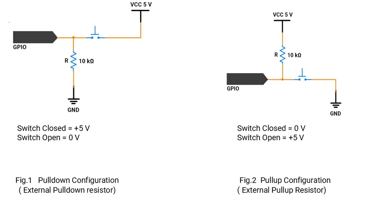
- Case 2: 3.3V supply: The approach is the same as above; simply use a 3.3V supply instead of 5V where applicable.
However, most microcontrollers’ GPIO pins include an internal pull-up resistor, which can be used for interfacing the switch.
Therefore, it is recommended to enable the internal pull-up resistor in your microcontroller’s settings.
So, by selecting a proper resistor, LED, and push-button switch, we can implement the task.
Below are the solutions to the given task using different microcontrollers
- STM32
- ESP32
- Arduino UNO
We’re using an STM32 NUCLEO-F103RB board, which runs at a 3.3V logic level.
Key Peripherals Used:
- GPIO: To connect a push-button switch and LEDs.
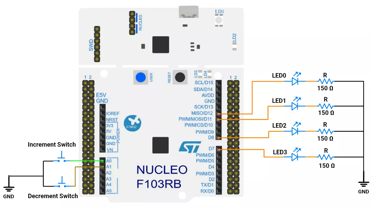
STM32 Hardware Connection
- Switch: Connect one terminal of each push-button switch to GPIO pins PA0 and PA1, and the other terminals to GND. Enable the internal pull-up resistor for PA0 and PA1 in the software.
- LEDs: Connect anodes of LED0, LED1, LED2, and LED3, to GPIO pins PA6(D12), PA7(D11), PA9(D9), and PA8(D7) respectively. Connect their cathodes to ground through appropriate resistors.
Circuit Diagram
STM32 Firmware Implementation
Project Setup in STM32CubeIDE:
- Create a Project
- Open STM32CubeIDE and start a new project, select the NUCLEO-F103RB board.
- Basic Configuration (via CubeMX inside CubeIDE)
- Clock: Keep the default internal oscillator (no custom changes needed).
- GPIO Configuration:
- Switch: Set GPIO PA0 and PA1 as GPIO Input Pull-Up in the Pinout view (via STM32CubeMX, built into CubeIDE).
- LEDs: Set GPIO PA6, PA7, PA9, and PA8 as GPIO Output Push-Pull in the Pinout view (via STM32CubeMX, built into CubeIDE).
- Code Generation
- CubeMX will automatically generate all the startup code, including:
HAL_Init()→ Initializes the HAL library.SystemClock_Config()→ Configures system clock.MX_GPIO_Init()→ Configures GPIO pins.
- This code sets up the hardware and prepares the project for firmware development, so we only need to add our application logic in the user code sections
- CubeMX will automatically generate all the startup code, including:
Code Snippets from main.c
GPIO Initialization
// In MX_GPIO_Init()
 /*Configure GPIO pin Output Level */
 HAL_GPIO_WritePin(GPIOA, GPIO_PIN_6|GPIO_PIN_7|GPIO_PIN_8|GPIO_PIN_9, GPIO_PIN_RESET);

/*Configure GPIO pins : PA0 PA1 */
 GPIO_InitStruct.Pin = GPIO_PIN_0|GPIO_PIN_1;
 GPIO_InitStruct.Mode = GPIO_MODE_INPUT;
 GPIO_InitStruct.Pull = GPIO_PULLUP;
 HAL_GPIO_Init(GPIOA, &GPIO_InitStruct);

/*Configure GPIO pins : PA6 PA7 PA8 PA9 */
 GPIO_InitStruct.Pin = GPIO_PIN_6|GPIO_PIN_7|GPIO_PIN_8|GPIO_PIN_9;
 GPIO_InitStruct.Mode = GPIO_MODE_OUTPUT_PP;
 GPIO_InitStruct.Pull = GPIO_NOPULL;
 GPIO_InitStruct.Speed = GPIO_SPEED_FREQ_LOW;
 HAL_GPIO_Init(GPIOA, &GPIO_InitStruct);
This configures pins PA0 and PA1 as digital inputs with an internal pull-up resistor enabled. The pull-up resistor ensures the input reads HIGH to prevent a floating input. And the pins PA6, PA7, PA8, and PA9 are configured as digital output pins using push-pull mode, which ensures they can actively drive the LEDs either HIGH or LOW with a strong and stable output.
Macros for Port and Pin
#define SWITCH0_PORT GPIOA
#define SWITCH0_PIN GPIO_PIN_0

#define SWITCH1_PORT GPIOA
#define SWITCH1_PIN GPIO_PIN_1

#define LED0_PORT GPIOA
#define LED0_PIN GPIO_PIN_6

#define LED1_PORT GPIOA
#define LED1_PIN GPIO_PIN_7

#define LED2_PORT GPIOA
#define LED2_PIN GPIO_PIN_9

#define LED3_PORT GPIOA
#define LED3_PIN GPIO_PIN_8
Defines easier-to-read names for the GPIO ports and pins of the switch and LEDs, improving code readability and maintainability.
Private Variable
uint8_t g_counter = 0;                          // Initial counter value
uint8_t g_debounceDelayMs = 50;         // Debounce delay time (in milliseconds)
uint32_t g_lastDebounceTimeMs[2] = { 0, 0 }; // Stores last debounce time for each switch
uint8_t g_lastButtonState[2] = { 1, 1 }; // Stores the last state of each button
uint8_t g_currentButtonState[2] = { 1, 1 }; // Store the current state of each button
GPIO_TypeDef *g_switchPortList[2] = { SWITCH0_PORT, SWITCH1_PORT };
uint16_t g_switchPinList[2] = { SWITCH0_PIN, SWITCH1_PIN };
g_counter: Holds the current 4-bit value (0-15). This number appears on the LEDs in binary.g_debounceDelayMs: Sets the debounce time to 50ms to filter out false triggers from noisy button presses.g_lastDebounceTimeMs: Records the last time a button state changed for debouncing.g_lastButtonState&g_currentButtonState: Track the previous and current signals of each button for comparison and debouncing.g_switchPortList&g_switchPinList: Arrays listing the GPIO port and pin for each button, allowing for cleaner, more scalable code.
Key Private functions
a) Timebase (non-blocking delays)
/**
 * @brief Returns milliseconds since system start.
 * Uses HAL_GetTick(), based on SysTick interrupt every 1 ms.
 * Useful for timing events without blocking execution.
 */
uint32_t millis() {
	return HAL_GetTick();
}
Returns milliseconds since system reset, driven by SysTick.
b) Debounced Button Press Checker
// Check if a button has been pressed with debouncing
uint8_t isButtonPressed(uint8_t buttonIndex) {
	int reading = HAL_GPIO_ReadPin(g_switchPortList[buttonIndex],
			g_switchPinList[buttonIndex]);
	// If the button state has changed
	if (reading != g_lastButtonState[buttonIndex]) {
		g_lastDebounceTimeMs[buttonIndex] = millis();    // Reset debounce timer
	}
	g_lastButtonState[buttonIndex] = reading;
	// If the state has remained stable for the debounce period(50 ms), consider it a valid press
	if ((millis() - g_lastDebounceTimeMs[buttonIndex]) > g_debounceDelayMs) {
		if (reading != g_currentButtonState[buttonIndex]) {
			g_currentButtonState[buttonIndex] = reading;
			// Checking if the button is pressed(LOW)
			if (g_currentButtonState[buttonIndex] == 0) {
				return 1;                // Return true indicating a valid press
			}
		}
	}
	return 0;                            // No valid press detected
}- Reads the button’s current state.
- If the state changed (button pressed or released), the debounce timer is restarted.
- Only after the state remains stable for the debounce interval (50ms) is the press considered valid.
- Handles both “pressed” (logic LOW when using pull-up) and “released” states, returning 1 for a confirmed new press, preventing response to false triggers, and “bouncing” (rapid, spurious transitions during a single press).
c) LED Output Update
// Update LEDs based on the current counter value
void updateLeds() {
	HAL_GPIO_WritePin(LED0_PORT, LED0_PIN, (g_counter >> 0) & 1);
	HAL_GPIO_WritePin(LED1_PORT, LED1_PIN, (g_counter >> 1) & 1);
	HAL_GPIO_WritePin(LED2_PORT, LED2_PIN, (g_counter >> 2) & 1);
	HAL_GPIO_WritePin(LED3_PORT, LED3_PIN, (g_counter >> 3) & 1);
}- Each call sets the LEDs to represent the current 4-bit binary value of
g_counter. - For example, if
g_counteris 10 (0b1010), LED0 and LED2 are OFF, LED1 and LED3 are ON. - Uses bitwise operations:
>>shifts bits to align with the LED, & 1 isolates the bit for each output.
Main Firmware Logic
int main(void) {
  /* Reset of all peripherals, Initializes the Flash interface and the Systick. */
  HAL_Init();

  /* Configure the system clock */
  SystemClock_Config();

  /* Initialize all configured peripherals */
  MX_GPIO_Init();
  MX_USART2_UART_Init();  //optional

  while (1) {
    // check increment switch
    if (isButtonPressed(0) && g_counter < 15) {
      g_counter++;
      updateLeds();
    }

    // check decrement switch
    if (isButtonPressed(1) && g_counter > 0) {
      g_counter--;
      updateLeds();
    }
  }
}- System and peripherals initialized (HAL, clocks, GPIO, UART if needed).
- Main loop: constantly checks both buttons.
- If the increment button is pressed and
g_counteris less than 15 (maximum 4-bit value), increaseg_counterby 1. - If the decrement button is pressed and
g_counteris greater than 0, it decreases it by 1. - After each change, update the LEDs via
updateLeds()to show the new value.
- If the increment button is pressed and
Download Project
The complete STM32CubeIDE project (including .ioc configuration, main.c, and HAL files) is available here:
We are using the ESP32 DevKit v4 development board and programming it using the Arduino IDE.
- Before uploading, make sure to select “ESP32 Dev Module” as the board to ensure correct settings and compatibility.
We will connect two push‑button switches and four LEDs to the ESP32 to design a 4‑bit binary counter.
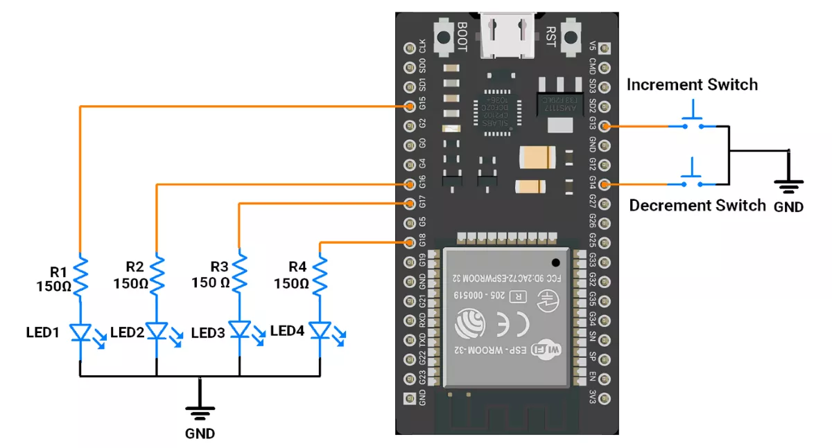
ESP32 Circuit Connection
Push‑Button Interfacing (Internal Pull‑up method):
- One terminal → GPIO pin.
- Other terminal → GND.
- In software, configure it as INPUT_PULLUP so the pin reads HIGH when idle and LOW when pressed.
LED Interfacing
- Each LED's anode is connected to GPIO pins 15,16,17, and 18 through a 150 Ω resistor.
- Each LED's cathode is connected to GND.
ESP32 Firmware Implementation
Code
uint8_t ledPins[4] = { 15, 16, 17, 18 };  // LED pins connected to pins 15, 16, 17, 18
uint8_t switchPins[2] = { 13, 14 };       // Switch pins connected to pins 13(increment),14(decrement)

uint8_t counter = 0;  // Initialize counter

uint8_t debounceDelay = 50;                    // Debounce delay time (in milliseconds)
unsigned long lastDebounceTime[2] = { 0, 0 };  // Stores last debounce time for each switch
bool lastButtonState[2] = { HIGH, HIGH };      // Stores the last state of each button
bool ButtonState[2] = { HIGH, HIGH };          // Store the current state of each button

void setup() {
  for (uint8_t i = 0; i < 4; i++) {
    pinMode(ledPins[i], OUTPUT);  // Initialize LED pins as OUTPUT
  }
  for (uint8_t i = 0; i < 2; i++) {
    pinMode(switchPins[i], INPUT_PULLUP);  // Initialize switch pins as INPUT_PULLUP
  }
}

void loop() {
  // check increment switch
  if (isButtonPressed(0) && counter < 15) {
    counter++;
    updateLEDs();
  }

  // check decrement switch
  if (isButtonPressed(1) && counter > 0) {
    counter--;
    updateLEDs();
  }
}

// Check if a button has been pressed with debouncing
bool isButtonPressed(uint8_t switchIndex) {

  int reading = digitalRead(switchPins[switchIndex]);

  // If the button state has changed
  if (reading != lastButtonState[switchIndex]) {
    lastDebounceTime[switchIndex] = millis();  // Reset debounce timer
  }
  lastButtonState[switchIndex] = reading;
  // If the state has remained stable for the debounce period(50 ms), consider it a valid press
  if ((millis() - lastDebounceTime[switchIndex]) > debounceDelay) {

    if (reading != ButtonState[switchIndex]) {
      ButtonState[switchIndex] = reading;
      // Checking if the button is pressed(LOW)
      if (ButtonState[switchIndex] == LOW) {
        return true;  //  valid button press detected
      }
    }
  }

  return false;  // No valid press detected
}

// Update LEDs based on the current counter value
void updateLEDs() {
  for (uint8_t i = 0; i < 4; i++) {
    digitalWrite(ledPins[i], (counter >> i) & 1);
  }
}
Code Explanation
- Pin Setup
- 4 LEDs are connected to pins 15, 16, 17, 18, stored in
ledPins[]. - 2 buttons are connected to pins 13 & 14, stored in
switchPins[].
- 4 LEDs are connected to pins 15, 16, 17, 18, stored in
- Counter Variable
- counter stores the current number (0–15).
- Each button press increases or decreases this counter.
- Debouncing Logic (
isButtonPressed())- The debounce code checks if the signal remains stable for 50 ms before considering it a valid press.
- Only when the button is stably pressed (LOW), it return true.
- Main Loop
- If button 0 (increment) is pressed and counter < 15, increase counter.
- If button 1 (decrement) is pressed and counter > 0, decrease counter.
- After any change,
updateLEDs()is called to update LEDs.
- Updating LEDs (
updateLEDs())- LEDs show the binary value of counter.
- Example: counter = 5 → binary 0101 → LEDs ON/OFF accordingly.
- This is done using bit shifting:
(counter >> i) & 1
We are using the Arduino UNO development board and programming it using the Arduino IDE.
- Before uploading, make sure to select “Arduino UNO” as the board to ensure correct settings and compatibility.
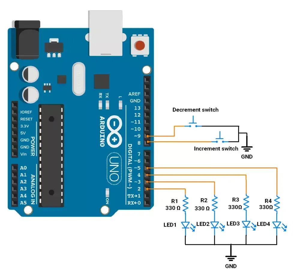
Arduino UNO Circuit Connection
- LEDs: Connect 4 LEDs to Arduino pins 2, 3, 4, 5 with 330 ohm resistors.
- Switches: Connect 2 push-buttons to pins 8 and 9 using an internal pull-up resistor.
Circuit Diagram
Arduino UNO Firmware Implementation
Code
uint8_t ledPins[4] = {2, 3, 4, 5};            // LED pins connected to pins 2, 3, 4, 5
uint8_t switchPins[2] = {8, 9};               // Switch pins connected to pins 8, 9

uint8_t counter = 0;                          // Initial counter value


uint8_t debounceDelay = 50;                    // Debounce delay time (in milliseconds)
unsigned long lastDebounceTime[2] = {0, 0};   // Stores last debounce time for each switch
uint8_t lastButtonState[2] = {HIGH, HIGH};    // Stores the last state of each button
uint8_t ButtonState[2] = {HIGH, HIGH};        // Store the current state of each button

void setup() {

  for (int i = 0; i < 4; i++) {
    pinMode(ledPins[i], OUTPUT);             // Initialize LED pins as OUTPUT
  }

  for (int i = 0; i < 2; i++) {
    pinMode(switchPins[i], INPUT_PULLUP);    // Initialize switch pins as INPUT_PULLUP
  }

}

void loop() {
  // check increment switch
  if (isButtonPressed(0) && counter < 15) {
    counter++;
    updateLEDs();
  }

  // check decrement switch
  if (isButtonPressed(1) && counter > 0) {
    counter--;
    updateLEDs();
  }
}

// Check if a button has been pressed with debouncing
bool isButtonPressed(uint8_t switchIndex) {

  int reading = digitalRead(switchPins[switchIndex]);

  // If the button state has changed
  if (reading != lastButtonState[switchIndex]) {
    lastDebounceTime[switchIndex] = millis();                 // Reset debounce timer
  }
  lastButtonState[switchIndex] = reading;
  // If the state has remained stable for the debounce period(50 ms), consider it a valid press
  if ((millis() - lastDebounceTime[switchIndex]) > debounceDelay) {

    if (reading !=ButtonState[switchIndex] ) {
     ButtonState[switchIndex] = reading;
     // Checking if the button is pressed(LOW)
      if (ButtonState[switchIndex] == LOW) {
        return true;                             // Return true indicating a valid press
      }
    }
  }

  return false;                            // No valid press detected
}

// Update LEDs based on the current counter value
void updateLEDs() {
  for (int i = 0; i < 4; i++) {
    digitalWrite(ledPins[i], (counter >> i) & 1);
  }
}
Code explanation
setup()- Configures 4 LED pins as
OUTPUT. - Configures 2 switch pins as
INPUT_PULLUP.
- Configures 4 LED pins as
loop()- Continuously checks switches:
- If increment switch pressed →
counter++(max 15). - If decrement switch pressed →
counter--(min 0). - Calls
updateLEDs()to update LED output.
- If increment switch pressed →
- Continuously checks switches:
isButtonPressed(switchIndex)- The function reads the button state and notes changes using
millis(). - If the state is stable for 50 ms, it treats it as a valid press (debouncing).
- This prevents false triggers from bouncing, without blocking code execution.
- The function reads the button state and notes changes using
updateLEDs()- Converts counter into binary.
- Updates each LED with (counter >> i) & 1.
Output
4-bit Binary Counter hardware setup