30. Interface LM35 temperature sensor
To connect and use the LM35 temperature sensor with a microcontroller, enabling accurate temperature measurement across the sensor’s full rated range.
Understanding the LM35 Sensor
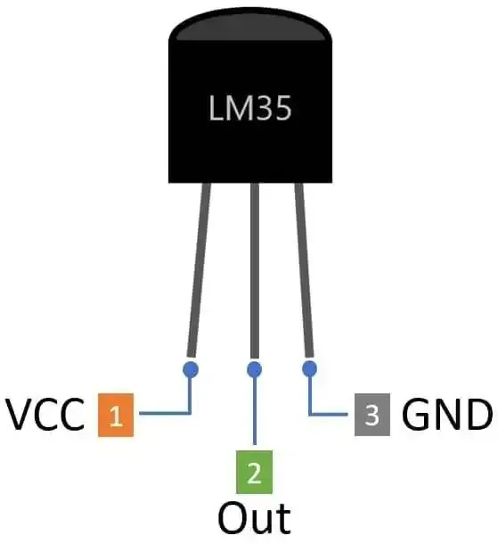
- Temperature Range: -55°C to +150°C
- Output Scale: 10 millivolts (mV) per 1°C
- Default Output Voltage:
- When GND = 0V, the OUT pin voltage ranges from -0.55V to +1.5V (corresponding to the sensor’s min/max temperatures)
- Output Formula:
- Output Voltage (V) = (Temperature in °C) × 10mV
Output Voltage Shifting: Why and How
Why Shift the Output?
- Most microcontroller ADCs (Analog-to-Digital Converters) only measure voltages in the 0–3.3V or 0–5V range.
- The LM35 can output negative voltages if the GND pin is at 0V and measures negative temperatures—these cannot be detected directly by most ADCs.
How to Shift the Output?
- Technique: Raise the voltage on the LM35’s GND pin above 0V (using a voltage divider).
- Effect: Shifts the LM35 OUT voltages into the positive range, ensuring all outputs fit within the ADC’s measurable limits.
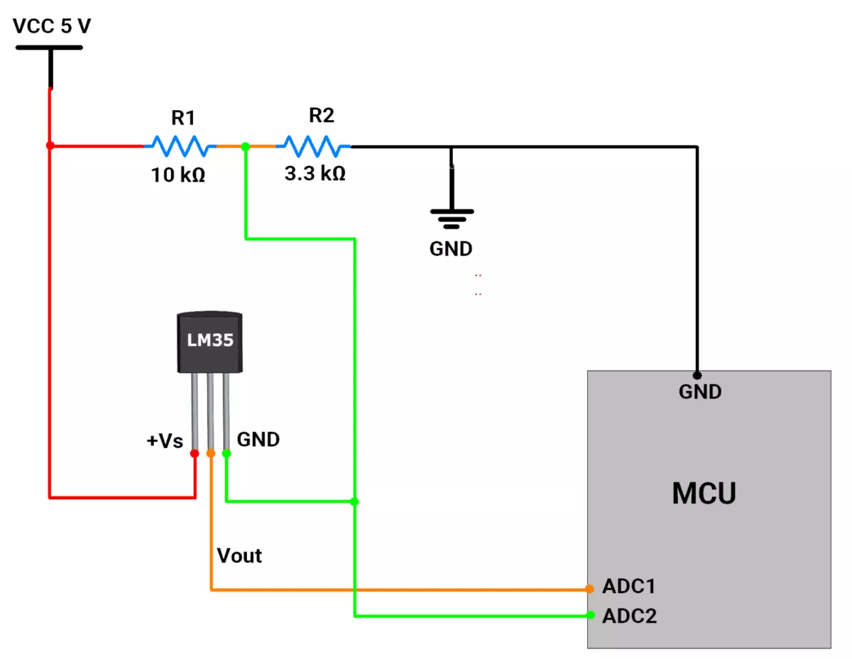
Using a Voltage Divider
- Construct a voltage divider with two resistors (R1 and R2) between the microcontroller’s supply voltage and ground.
- Voltage at the divider (Vshift):
Vshift = Vcc × (R2 / (R1+R2))
- Connect Vshift to the GND pin of the LM35.
- Choose R1 and R2 to set Vshift so that the entire LM35 output range (relative to shifted ground) fits within the ADC range.
Choosing R1 and R2
- Resistor values determine the shifted ground; choose them so your LM35 output always falls within the ADC’s range.
- Example:
- R1 = 10 kΩ, R2 = 3.3 kΩ (with Vcc = 5V)
- Vshift = 5 x ( 3300 / ( 10000 + 3300) = 1.24 V
- Corresponding Output Range:
- At -55 degrees Celsius: Vmin = Vshift + (-0.55V) = 0.69V
- At 150 degrees Celsius: Vmax = Vshift + (1.5V) = 2.74V
- Both values fall within typical ADC ranges (0–3.3V or 0–5V).
Circuit Connections Overview
- LM35 Vout:
- Connect to one ADC channel
- Voltage Divider Output (Vshift):
- Connects to the LM35 GND pin
- Also, connect to another ADC channel to monitor the reference shift
Measurement Process
- Read ADC1: Measures LM35 output voltage (Vout)
- Read ADC2: Measures the shifted ground voltage (Vshift)
- Calculate Sensor Voltage:
Vsensor = (VLM35 OUT) − Vshift
Temperature Calculation
- Convert Voltage to Temperature:
- Find the voltage difference (from above), in millivolts (mV)
- Use the scale factor:
Temperature (°C) = Voltage difference (mV) / 10
- e.g., 250mV difference = 25°C
Notes
- Select resistor values so that the shifted range matches your ADC’s capability.
- Optionally, use an op-amp buffer for the voltage divider to avoid a voltage drop if the sensor draws current.
- For best results, use precision resistors and ensure stable supply voltages.
Negative temperature detection
- Measuring negative temperature would require liquid nitrogen, but it is -196 °C. So, it will damage our sensor.
- Unfortunately, we will skip measuring negative temperature for the demonstration.
So, by considering the above points, we can implement the task. Below are the solutions to the given task using different microcontrollers
- STM32
- ESP32
- Arduino UNO
We’re using an STM32 NUCLEO-F103RB board, which runs at a 3.3V logic level.
Key Peripherals Used:
- ADC1 Channel 0 (PA0): Reads the analog voltage from the sensor Vout pin.
- ADC2 Channel 1 (PA1): Reads the analog voltage of Vref connected to the GND pin of the sensor.
- USART2: For serial communication with a serial terminal to display the measured temperature.
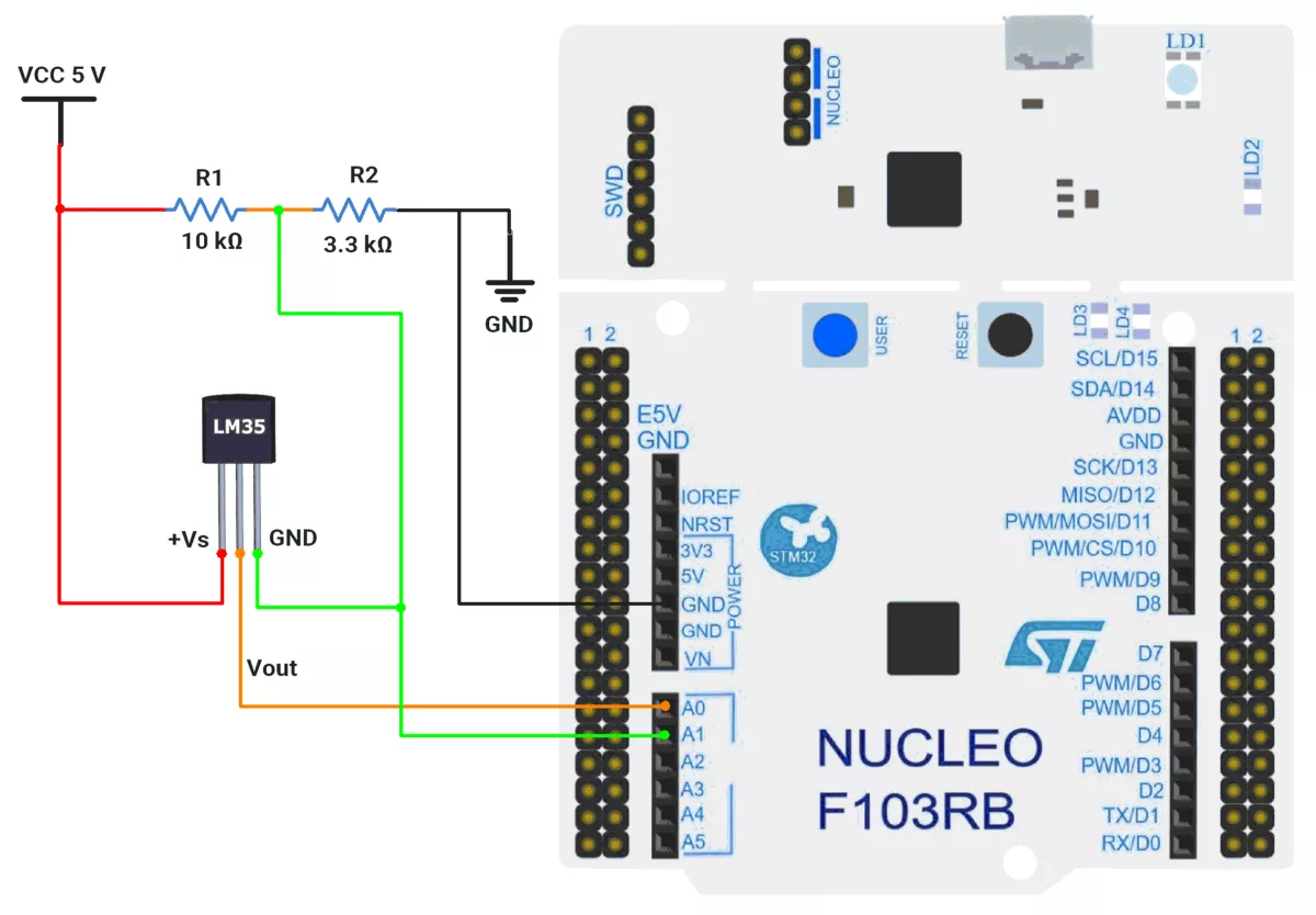
STM32 Hardware Connection
- LM35 Sensor connection:
- Connect VCC 5V to the sensor’s +Vs pin.
- Connect the sensor’s Vout pin to PA0 (ADC1_IN0) for analog input.
- Create a voltage divider using R1 and R2 and apply 5V and GND to it.
- Connect the divided voltage to the sensor’s GND pin and PA1(ADC2_IN1).
- Use USART2 on the STM32 board for serial communication to display the measured voltage value on a serial terminal. This typically connects to the USB interface from the board to the PC.
- Power the STM32 board through the USB cable connected to your computer for both power and UART communication.
Circuit Diagram
STM32 Firmware Implementation
Project Setup in STM32CubeIDE
- Create a Project
- Open STM32CubeIDE, start a new project, and select the NUCLEO-F103RB board.
- Basic Configuration (via CubeMX inside CubeIDE)
- Clock: Use the default HSI oscillator with PLL enabled (as configured in
SystemClock_Config). - GPIO: Enable clocks for PORTA, PORTB, PORTC, and PORTD.
- ADC Configuration
- Two ADC peripherals used: ADC1 and ADC2.
- ADC1
- Channel:
ADC_CHANNEL_0 (PA0). - Mode: Single conversion, software-triggered.
- Resolution: 12-bit (0–4095).
- Channel:
- ADC2
- Channel:
ADC_CHANNEL_1 (PA1). - Same settings as ADC1.
- Channel:
- Sampling time: 239.5 cycles for better accuracy.
- Both ADCs use polling mode for conversion.
- USART2: Enabled at 115200 baud, 8-N-1.
- Clock: Use the default HSI oscillator with PLL enabled (as configured in
- Code Generation
- CubeMX will automatically generate all the startup code, including:
HAL_Init()→ Initializes HAL and system tick.SystemClock_Config()→ Configures system clock (HSI + PLL).MX_GPIO_Init()→ Initializes GPIO ports.MX_USART2_UART_Init()→ Configures UART2.MX_ADC1_Init()→ Configures ADC1 for analog input.MX_ADC2_Init()→ Configures ADC2 for analog input.
- This code sets up the hardware and prepares the project for firmware development, so we only need to add our application logic in the user code sections
- CubeMX will automatically generate all the startup code, including:
Code Snippets from main.c
ADC Initialization (MX_ADC1_Init and MX_ADC2_Init):
static void MX_ADC1_Init(void)
{
  ADC_ChannelConfTypeDef sConfig = {0};

  /** Common config
  */
  hadc1.Instance = ADC1;
  hadc1.Init.ScanConvMode = ADC_SCAN_DISABLE;
  hadc1.Init.ContinuousConvMode = DISABLE;
  hadc1.Init.DiscontinuousConvMode = DISABLE;
  hadc1.Init.ExternalTrigConv = ADC_SOFTWARE_START;
  hadc1.Init.DataAlign = ADC_DATAALIGN_RIGHT;
  hadc1.Init.NbrOfConversion = 1;
  if (HAL_ADC_Init(&hadc1) != HAL_OK)
  {
    Error_Handler();
  }

  /** Configure Regular Channel
  */
  sConfig.Channel = ADC_CHANNEL_0;
  sConfig.Rank = ADC_REGULAR_RANK_1;
  sConfig.SamplingTime = ADC_SAMPLETIME_239CYCLES_5;
  if (HAL_ADC_ConfigChannel(&hadc1, &sConfig) != HAL_OK)
  {
    Error_Handler();
  }

}
Similarly, for ADC2 also
This configures ADC1 and ADC2 for single-channel operation with right-aligned 12-bit results.
UART2 Initialization (MX_USART2_UART_Init):
static void MX_USART2_UART_Init(void)
{
  huart2.Instance = USART2;
  huart2.Init.BaudRate = 115200;
  huart2.Init.WordLength = UART_WORDLENGTH_8B;
  huart2.Init.StopBits = UART_STOPBITS_1;
  huart2.Init.Parity = UART_PARITY_NONE;
  huart2.Init.Mode = UART_MODE_TX_RX;
  huart2.Init.HwFlowCtl = UART_HWCONTROL_NONE;
  huart2.Init.OverSampling = UART_OVERSAMPLING_16;
  if (HAL_UART_Init(&huart2) != HAL_OK)
  {
    Error_Handler();
  }
}
This configures USART2 for communication at a 115200 baud rate with 8 data bits, no parity, and 1 stop bit, supporting both transmit and receive.
Header includes:
#include<string.h>
#include<stdio.h>
Private defines and variables:
#define ADC_SAMPLES 100       // Number of samples for averaging
#define ADC_RESOLUTION 4096   // 12-bit ADC resolution
#define REFERENCE_VOLTAGE 3.28f //Measured Reference voltage

uint32_t adcValues[2];    // Buffer for two channels
char uartBuffer[64];   // Buffer for UART messages
Main Loop - Reading and Transmitting temperature
while (1) {
  uint32_t sumCh0 = 0, sumCh1 = 0;
  uint8_t validSamplesCh0 = 0, validSamplesCh1 = 0;
  float voltageDiff = 0;
  int16_t tempValue = 0;
  int16_t tempDecimalValue = 0;

  // Take multiple samples for averaging
  for (int i = 0; i < ADC_SAMPLES; i++) {
    // Read channel 0
    HAL_ADC_Start(&hadc1);
    if (HAL_ADC_PollForConversion(&hadc1, 20) == HAL_OK) {
      sumCh0 += HAL_ADC_GetValue(&hadc1);
      validSamplesCh0++;
    }

    // Read channel 1
    HAL_ADC_Start(&hadc2);
    if (HAL_ADC_PollForConversion(&hadc2, 20) == HAL_OK) {
      sumCh1 += HAL_ADC_GetValue(&hadc2);
      validSamplesCh1++;
    }
  }

  // Calculate average values only if we have valid samples
  if (validSamplesCh0 > 0 && validSamplesCh1 > 0) {
    adcValues[0] = sumCh0 / validSamplesCh0;
    adcValues[1] = sumCh1 / validSamplesCh1;

    // Calculate absolute difference once
    uint32_t adcDiff =
      (adcValues[0] >= adcValues[1]) ? (adcValues[0] - adcValues[1]) : (adcValues[1] - adcValues[0]);

    if (adcDiff != 0) {
      voltageDiff = (REFERENCE_VOLTAGE * adcDiff) / ADC_RESOLUTION;
    }

    if (voltageDiff != 0) {
      tempValue = voltageDiff * 100;
      tempDecimalValue = (int16_t)(voltageDiff * 10000) % 100;
    }


    // Format message based on which channel is higher
    if (adcValues[0] >= adcValues[1]) {
      sprintf(uartBuffer, "Temperature: %u.%u Degree Celsius \r\n",
              tempValue, tempDecimalValue);
    } else {
      sprintf(uartBuffer, "Temperature: -%u.%u Degree Celsius \r\n",
              tempValue, tempDecimalValue);
    }

    // Send Temperature value on UART
    HAL_UART_Transmit(&huart2, (uint8_t*)uartBuffer,
                      strlen(uartBuffer), HAL_MAX_DELAY);
  } else {
    // Handle error case if needed
    sprintf(uartBuffer, "ADC read error\r\n");
    HAL_UART_Transmit(&huart2, (uint8_t*)uartBuffer,
                      strlen(uartBuffer), HAL_MAX_DELAY);
  }

  HAL_Delay(1000);
}
Main Loop Workflow
- Loop Forever (
while (1))- Continuously reads, processes, and sends temperature data.
- Read & Average ADC Samples
- Takes multiple samples from Channel 0 (
ADC1) and Channel 1 (ADC2). - Computes the average ADC value for each channel.
- Takes multiple samples from Channel 0 (
- Calculate Voltage Difference
- Finds the absolute difference between the two ADC values.
- Converts this difference to a voltage (
voltageDiff).
- Compute Temperature
- Extracts:
- Integer part (
tempValue = voltageDiff * 100). - Decimal part (tempDecimalValue = (
voltageDiff * 10000) % 100).
- Integer part (
- Extracts:
- Determine Sign & Format Output
- If Channel 0 ≥ Channel 1 → Positive temperature (e.g., "
25.5°C"). - If Channel 0 < Channel 1 → Negative temperature (e.g., "
-10.2°C").
- If Channel 0 ≥ Channel 1 → Positive temperature (e.g., "
- Send Temperature via UART
- Transmits a formatted string (or an error if ADC read fails).
- Wait 1 Second (
HAL_Delay(1000)) before repeating.
Download Project
The complete STM32CubeIDE project (including .ioc configuration, main.c, and HAL files) is available here:
We are using the ESP32 DevKitC v4 development board and programming it using the Arduino IDE
- Before uploading, make sure to select “ESP32 Dev Module” as the board to ensure correct settings and compatibility.
ESP32 Circuit Connection
Let’s do the hardware connection.
LM35 Sensor connection:
- Connect VCC 5V to the sensor’s +Vs pin.
- Connect the sensor’s Vout pin to GPIO pin 34 for analog input.
- Create a voltage divider using R1 and R2 and apply 5V and GND to it.
- Connect the divided voltage to the sensor’s GND pin and GPIO pin 35.
- Connect the board through the USB cable to the computer for both power and UART communication.
Circuit connection
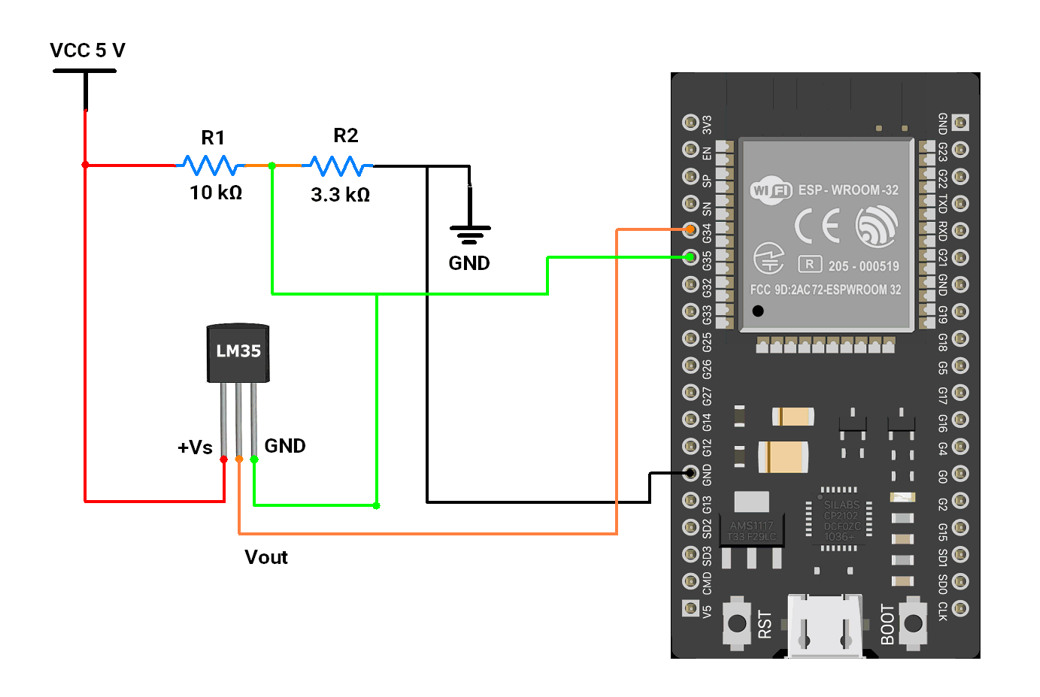
- The voltage at the GND pin is 1.241 Volts, which will shift the negative voltage on the Vout pin to positive voltages by 1.241 Volts.
Firmware Implementation
Let’s write code,
- Read the voltage on both Analog pins.
- Subtract the offset voltage (LM35 reference) 1.241 Volts.
- Convert voltage to temperature
- Print the temperature on the Serial Monitor. We can also connect an LCD & display the temperature on it. For this task, we will use the Serial monitor.
Code
const int lm35_pin   = 34;  // LM35 output
const int offset_pin = 35;  // "Ground" offset reading

float offset_voltage = 0;

int temp_adc_val;
float temp_val;

void setup() {
  Serial.begin(115200);
}

void loop() {
  // Read temperature sensor
  temp_adc_val = analogRead(lm35_pin);

  // Read offset pin (same logic as original code)
  offset_voltage = analogRead(offset_pin) * (3300.0 / 4095.0);
  // Convert to millivolts (ESP32 = 3.3V, 12-bit ADC)

  // Convert LM35 ADC reading to millivolts
  temp_val = temp_adc_val * (3300.0 / 4095.0);

  // Subtract offset
  temp_val = temp_val - offset_voltage;

  // LM35 scale: 10 mV per °C
  temp_val = temp_val / 10.0;

  Serial.print("Temperature = ");
  Serial.print(temp_val);
  Serial.println(" Degree Celsius");

  delay(1000);
}
Code Explanation
float temp_val = adcValue * (3300 / 4095);- Converts the ADC reading to millivolts because the ESP32 ADC range is 0–3300 mV at 12-bit resolution (0–4095).
temp_val = temp_val - offset_voltage;- Removes the offset voltage read from the second ADC pin (used to measure ground drift/noise).
temp_val = temp_val / 10;- LM35 outputs 10 mV per °C, so dividing the millivolt value by 10 gives the temperature in °C.
We are using the Arduino UNO development board and programming it using the Arduino IDE.
- Before uploading, make sure to select “Arduino UNO” as the board to ensure correct settings and compatibility.
Let’s do the hardware connection.
LM35 Sensor connection:
- Connect VCC 5V to the sensor’s +Vs pin.
- Connect the sensor’s Vout pin to A0 for analog input.
- Create a voltage divider using R1 and R2 and apply 5V and GND to it.
- Connect the divided voltage to the sensor’s GND pin and A1.
- Connect the board through the USB cable to computer for both power and UART communication.
Hardware Connections
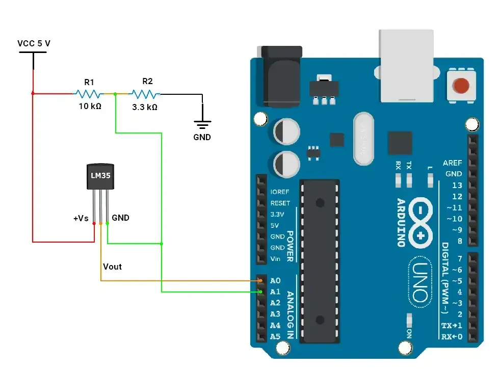
- The voltage at the GND pin is 1.241 Volts, which will shift the negative voltage on the Vout pin to positive voltages by 1.241 Volts.
Arduino UNO Firmware Implementation
Let’s write code
- Read voltage on both Analog pins.
- Subtract the offset voltage (LM35 reference) 1.241 Volts.
- Convert voltage to temperature
- Print the temperature on the Serial Monitor. We can also connect an LCD & display temperature on it. For this task, we will use the Serial monitor.
Code
const int lm35_pin = A0;   /* LM35 O/P pin */
const int offset_pin = A1; /* LM35 GND pin */
float offset_voltage = 0;  /* offset voltage stored in milli-volts */

int temp_adc_val;
float temp_val;

void setup() {
  Serial.begin(9600);
}

void loop() {
  temp_adc_val = analogRead(lm35_pin);
  offset_voltage = analogRead(offset_pin) * (5000 / 1024); /* read offset voltage on A1 pin and convert it to milli-volts */

  temp_val = temp_adc_val * (5000 / 1024); /* Convert adc value to equivalent voltage (milli-volts) */
  temp_val = temp_val - offset_voltage;    /* remove the offset voltage */
  temp_val = (temp_val / 10);              /* LM35 gives output of 10mv/°C */

  Serial.print("Temperature = "); /* Print the temprature*/
  Serial.print(temp_val);
  Serial.println(" Degree Celsius");
  delay(1000);
}
Code explanation
float temp_val = adcValue * (5000 / 1024): converts ADC_value to voltage (milli volts).temp_val = temp_val - offset_voltage:removes the offset voltage, that is given to the GND pin.temp_val = (temp_val/10): converts into degree Celsius (1 degree Celsius = 10mV).
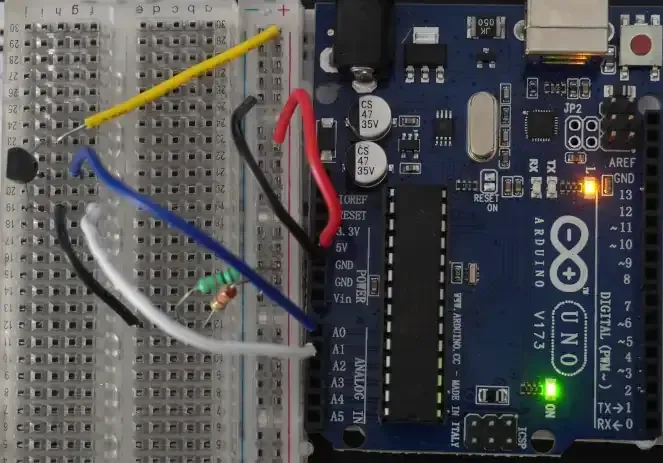
Output
Hardware Setup
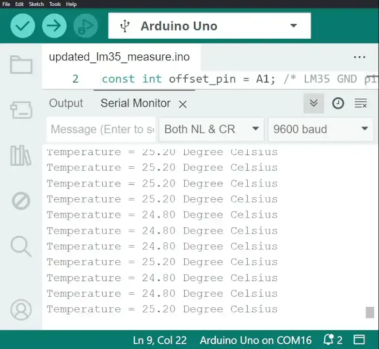
Output video
As we can see in the video, the temperature change is successfully detected and printed on the Serial monitor.