
63. LED Blink Rate Control
- From the task, we can understand we have to design a blink rate control system where the LED's blinking rate is controlled by the Potentiometer's position. The Rate will also be between 100ms to 5000ms.
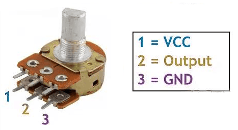
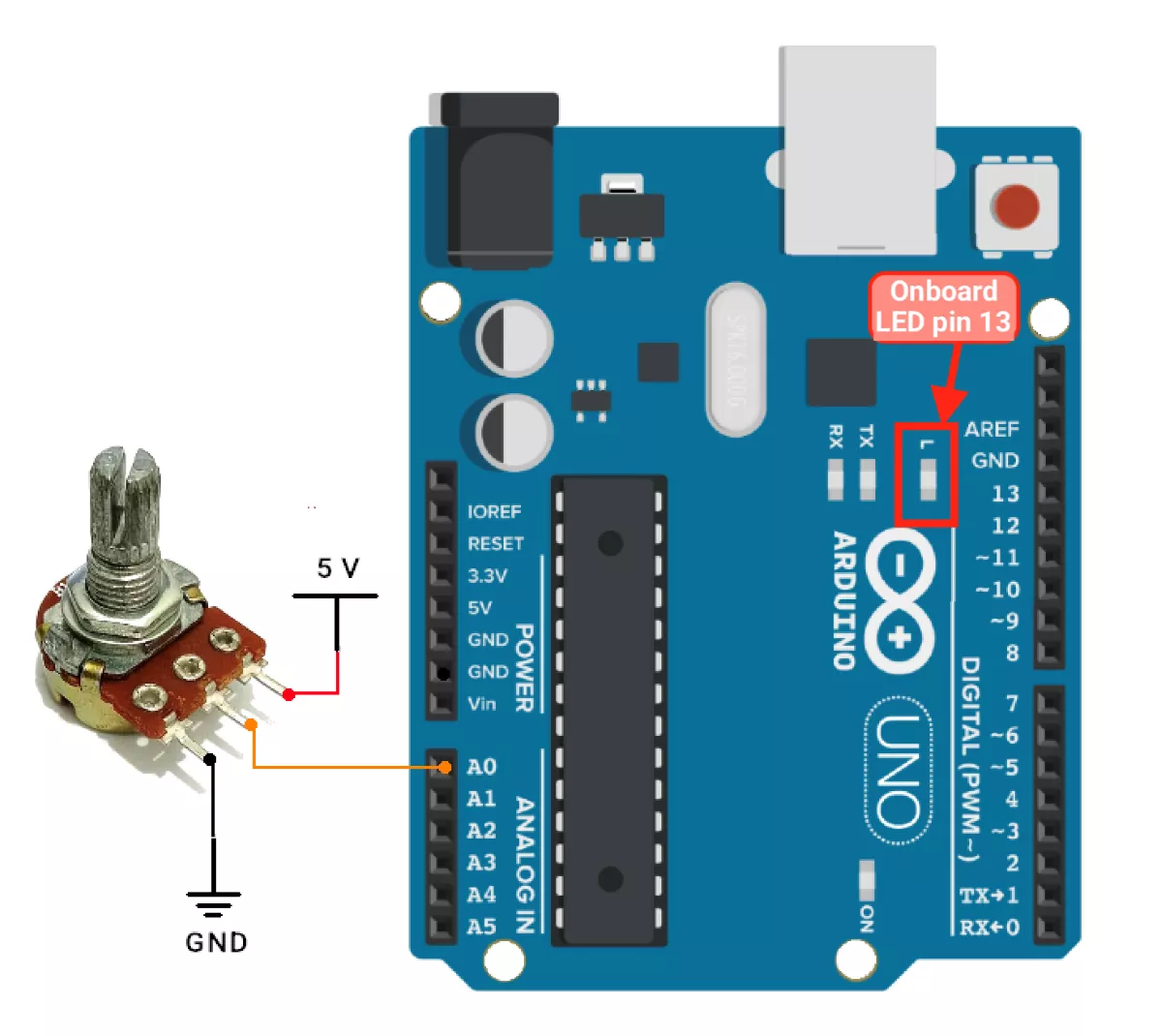
- We can connect an LED to pin 13 and connect the Output pin (2) of the potentiometer to the A0 pin while the terminal pins 1 and 3 connect to Vcc and GND respectively.
- The potentiometer is connected to an analog pin A0, and its value (0-1023) determines the blink interval i.e. 100ms to 5000ms.
- We will use the ADC interrupt to handle analog-to-digital conversions (reading the potentiometer value). The interrupt triggers whenever the conversion is complete, allowing the blink interval to update instantly.
- In the
ISR(ADC_vect), we will usemillis()to implement non-blocking LED blinking so the system can handle interrupts and blink simultaneously.
Circuit Connection
Code
// Pin Definitions
#define LED_PIN 13  // LED connected to pin 13
#define POT_PIN A0  // Potentiometer connected to analog pin A0

// Variables
volatile unsigned long blinkInterval = 1000;  // Blink interval (ms), default 1000ms
volatile unsigned long lastBlinkTime = 0;     // Last time the LED was toggled
volatile bool ledState = LOW;                 // Current LED state
volatile unsigned int adcValue = 0;           // Stores the latest ADC value

void setup() {
  // Configure LED pin as output
  pinMode(LED_PIN, OUTPUT);

  // Configure ADC for potentiometer reading
  ADMUX = (1 << REFS0);                                   // Set reference voltage to AVcc (5V)
  ADMUX |= POT_PIN;                                       // Select A0 (POT_PIN) as ADC input channel
  ADCSRA = (1 << ADEN)                                    // Enable ADC
           | (1 << ADIE)                                  // Enable ADC interrupt
           | (1 << ADPS2) | (1 << ADPS1) | (1 << ADPS0);  // Prescaler 128
  ADCSRA |= (1 << ADSC);                                  // Start the first conversion

  // Enable global interrupts
  sei();
}

void loop() {
  while (true) {
    //In this loop Microcontroller is busy in monitoring and performing important tasks constantly.
  }
}

// ADC Interrupt Service Routine
ISR(ADC_vect) {
  unsigned long currentTime = millis();

  // Read ADC value and map it to blink interval (100ms to 5000ms)
  unsigned int adcValue = analogRead(A0);
  blinkInterval = map(adcValue, 0, 1023, 100, 5000);

  // Check if enough time has passed to toggle LED
  if (currentTime - lastBlinkTime >= blinkInterval) {
    lastBlinkTime = currentTime;
    ledState = !ledState;  // Toggle LED state
    digitalWrite(LED_PIN, ledState);
  }

  // Start next ADC conversion
  ADCSRA |= (1 << ADSC);
}
Code Explanation
The code flows as follows
- Start the ADC conversion (on ADC pin A0).
- After ADC conversion is complete → ADC Interrupt occurs.
- ADC ISR →
- Read ADC-value.
- Update blink-delay wrt ADC-value.
- Check if the
currentTime - lastBlinkTime >= blinkInterval→ yes: toggle LED
- Start ADC conversion again.
Mapping ADC Values:
map(adcValue, 0, 1023, 100, 5000): Maps the ADC value (0–1023) to a range of 100ms to 5000ms for the blink interval.
Starts the ADC conversion:
ADCSRA |= (1 << ADSC);
ADC setup:
ADMUX = (1 << REFS0);- Sets the ADC reference voltage to
AVcc (5V)by setting theREFS0bit in the ADMUX register.
- Sets the ADC reference voltage to
ADMUX |= POT_PIN;- Select the ADC input channel (e.g.,
A0) by setting theMUX3:0bits inADMUX.POT_PINdefines the channel (e.g., 0 forA0).
- Select the ADC input channel (e.g.,
ADCSRA = (1 << ADEN) | (1 << ADIE) | (1 << ADPS2) | (1 << ADPS1) | (1 << ADPS0);- Enables the ADC (
ADEN), enables ADC interrupts (ADIE), and sets the ADC prescaler to 128 for a stable clock.
- Enables the ADC (
ADCSRA |= (1 << ADSC);- Start the first ADC conversion by setting the
ADSCbit. The result will be available in theADCregister after conversion.
- Start the first ADC conversion by setting the
What is happening in the setup?
- Configures ADC to use AVcc as a reference and select an input channel.
- Enables ADC, sets prescaler to 128, and starts the first conversion.
OUTPUT
Hardware Setup

Video