11. LED Blinking Patterns
First, we need to connect four LEDs to the microcontroller. And we need a proper resistor for each LED to limit the current flowing through them to 10mA.
Calculating the Resistor Value
To ensure a 10 mA current through the LED, we need to select an appropriate resistor based on the supply voltage.
Case 1: 5V Supply
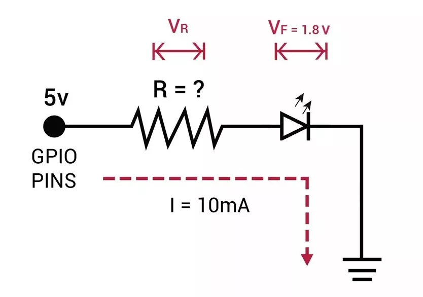
- LED forward voltage (Vf) = 1.8V (from datasheet)
- Voltage across resistor (VR) = Supply voltage – Vf = 5V – 1.8V = 3.2V
- Resistor value (R) = VR / I = 3.2V / 10 mA = 320 Ω
Standard resistor values near 320 Ω: 330 Ω or 300 Ω (whichever is available).
Similarly, Case 2: 3.3V Supply
- Voltage across resistor (VR) = 3.3V – 1.8V = 1.5V
- Resistor value (R) = 1.5V / 10 mA = 150 Ω
Standard resistor value: 150 Ω.
Interfacing the push button switch
To change the LED blinking pattern, use a push-button switch. When connecting the switch, ensure it correctly provides GPIO levels (LOW and HIGH). For reliable detection of voltage levels, use either a pull-up or pull-down resistor configuration.
- Case 1: 5V supply
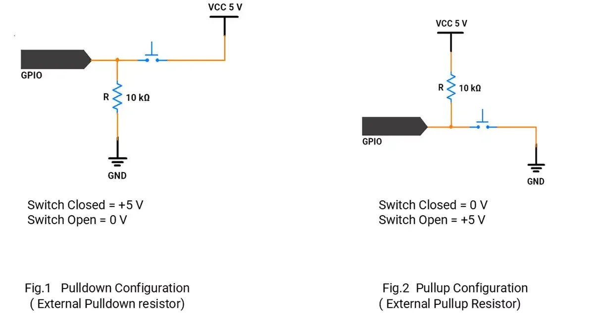
- Case 2: 3.3V supply: The approach is the same as above; simply use a 3.3V supply instead of 5V where applicable.
However, most microcontrollers’ GPIO pins include an internal pull-up resistor, which can be used for interfacing with the switch.
Therefore, it is recommended to enable the internal pull-up resistor in your microcontroller’s settings.
So, by selecting a proper resistor, LED, and push-button switch correctly, we can implement the task.
Below are the solutions to the given task using different microcontrollers
- STM32
- ESP32
- Arduino UNO
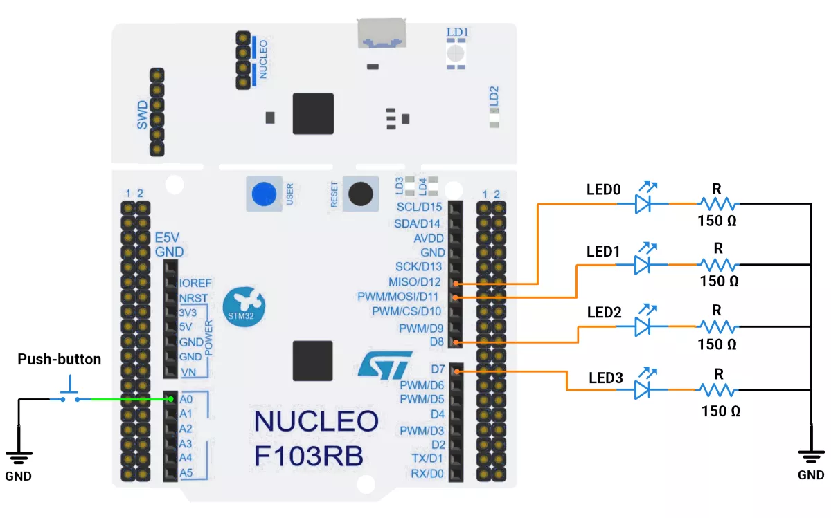
We’re using an STM32 NUCLEO-F103RB board, which runs at a 3.3V logic level.
Key Peripherals Used:
- GPIO: To connect a push-button switch and LEDs.
STM32 Hardware Connection
- Switch: Connect one terminal of the push-button switch to GPIO pin PA0 and the other terminal to GND. Enable the internal pull-up resistor for PA0 in the software.
- LEDs: Connect anodes of LED0, LED1, LED2, and LED3, to GPIO pins PA6(D12), PA7(D11), PA9(D8), and PA8(D7) respectively. Connect their cathodes to ground through appropriate resistors.
Circuit Diagram
STM32 Firmware Implementation
Project Setup in STM32CubeIDE:
- Create a Project
- Open STM32CubeIDE and start a new project, select the NUCLEO-F103RB board.
- Basic Configuration (via CubeMX inside CubeIDE)
- Clock: Keep the default internal oscillator (no custom changes needed).
- GPIO Configuration:
- Switch: Set GPIO PA0 as GPIO Input Pull-Up in the Pinout view (via STM32CubeMX, built into CubeIDE).
- LEDs: Set GPIO PA6, PA7, PA9, and PA8 as GPIO Output Push-Pull in the Pinout view (via STM32CubeMX, built into CubeIDE).
- Code Generation
- CubeMX will automatically generate all the startup code, including:
HAL_Init()→ Initializes the HAL library.SystemClock_Config()→ Configures system clock.MX_GPIO_Init()→ Configures GPIO pins.
- This code sets up the hardware and prepares the project for firmware development, so we only need to add our application logic in the user code sections
- CubeMX will automatically generate all the startup code, including:
Code Snippets from main.c
GPIO Initialization
// In MX_GPIO_Init()

  /*Configure GPIO pin Output Level */
 HAL_GPIO_WritePin(GPIOA, GPIO_PIN_6|GPIO_PIN_7|GPIO_PIN_8|GPIO_PIN_9, GPIO_PIN_RESET);

 /*Configure GPIO pin : PA0 */
 GPIO_InitStruct.Pin = GPIO_PIN_0;
 GPIO_InitStruct.Mode = GPIO_MODE_INPUT;
 GPIO_InitStruct.Pull = GPIO_PULLUP;
 HAL_GPIO_Init(GPIOA, &GPIO_InitStruct);

 /*Configure GPIO pins : PA6 PA7 PA8 PA9 */
 GPIO_InitStruct.Pin = GPIO_PIN_6|GPIO_PIN_7|GPIO_PIN_8|GPIO_PIN_9;
 GPIO_InitStruct.Mode = GPIO_MODE_OUTPUT_PP;
 GPIO_InitStruct.Pull = GPIO_NOPULL;
 GPIO_InitStruct.Speed = GPIO_SPEED_FREQ_LOW;
 HAL_GPIO_Init(GPIOA, &GPIO_InitStruct);
This configures pin PA0 as a digital input with an internal pull-up resistor enabled. The pull-up resistor ensures the input reads HIGH to prevent a floating input. And the pins PA6, PA7, PA8, and PA9 are configured as digital output pins using push-pull mode, which ensures they can actively drive the LEDs either HIGH or LOW with a strong and stable output.
Macros for Port and Pin
#define SWITCH0_PORT GPIOA
#define SWITCH0_PIN GPIO_PIN_0

#define LED0_PORT GPIOA
#define LED0_PIN GPIO_PIN_6

#define LED1_PORT GPIOA
#define LED1_PIN GPIO_PIN_7

#define LED2_PORT GPIOA
#define LED2_PIN GPIO_PIN_9

#define LED3_PORT GPIOA
#define LED3_PIN GPIO_PIN_8
Defines easier-to-read names for the GPIO ports and pins of the switch and LEDs, improving code readability and maintainability.
Private Variable
uint8_t g_debounceDuration = 50; // Minimum time to debounce button (in milliseconds)
uint8_t g_previousButtonState = 1;       // Previous state of the button
uint8_t g_currentButtonState = 1;        // Current state of the button
uint32_t g_lastDebounceTime = 0;   // Time when button state last changed
uint32_t g_pressStartTime;         // Time when button press starts
uint32_t g_releaseTime;             // Duration of the button press
// Arrays related to LED Patterns
const uint8_t g_patternLengths[] = { 2, 2, 4, 2, 2 };
const uint8_t g_patterns[][4][4] = { { { 1, 1, 1, 1 }, { 0, 0, 0, 0 } }, // Pattern 0
		{ { 1, 0, 1, 0 }, { 0, 1, 0, 1 } },                         // Pattern 1
		{ { 1, 0, 0, 0 }, { 0, 1, 0, 0 }, { 0, 0, 1, 0 }, { 0, 0, 0, 1 } }, // Pattern 2
		{ { 1, 1, 0, 0 }, { 0, 0, 1, 1 } },                         // Pattern 3
		{ { 1, 0, 0, 1 }, { 0, 1, 1, 0 } }                          // Pattern 4
};
uint8_t g_flagCheck = 1;         // Controls the execution of the current pattern
uint8_t g_patternIndex = 0;                // Current pattern index
Handles pattern logic and button state for robust switching and control.
Key Private functions
a) Timebase (non-blocking delays):
/**
 * @brief Returns milliseconds since system start.
 * Uses HAL_GetTick(), based on SysTick interrupt every 1 ms.
 * Useful for timing events without blocking execution.
 */
uint32_t millis() {
	return HAL_GetTick();
}
Returns milliseconds since system reset, driven by SysTick.
b) Button Debounce Logic:
//Checks for a debounced button press and returns true if detected, false otherwise.
uint8_t checkDebouncedButtonPress(GPIO_TypeDef *GPIOx, uint16_t GPIO_Pin,
		uint8_t expectedState) {
	uint8_t buttonReading = HAL_GPIO_ReadPin(GPIOx, GPIO_Pin);
	// If the button state has changed, reset the debounce timer
	if (buttonReading != g_previousButtonState) {
		g_lastDebounceTime = millis();
	}
	g_previousButtonState = buttonReading;
	// If the state has remained stable beyond the debounce duration, consider it valid
	if ((millis() - g_lastDebounceTime) > g_debounceDuration) {
		if (buttonReading != g_currentButtonState) {
			g_currentButtonState = buttonReading;
			if (g_currentButtonState == expectedState) {
				return 1; // Return true if the desired state is detected
			}
		}
	}
	return 0; // Return false if no valid press is detected
}
Ensures only clean, stable button presses are registered, preventing noise triggers.
Delay with Button Check:
// Implements a delay while checking for button press.
uint8_t delayWithButtonCheck(uint32_t delayDuration) {
	uint32_t delayStartTime = millis(); // Record the start time of the delay
	while ((millis() - delayStartTime) < delayDuration) {
		if (checkDebouncedButtonPress(SWITCH0_PORT, SWITCH0_PIN, 0)) {
			g_patternIndex = (g_patternIndex + 1) % 5; // Cycle to the next pattern
			return 0;                            // Exit delay early
		}
	}
	return 1; // Continue executing the pattern
}
Implements a timed wait, but remains responsive to button presses for pattern switching.
Set LEDs:
// Set the states of the LEDs
void setLeds(const uint8_t states[]) {
	HAL_GPIO_WritePin(LED0_PORT, LED0_PIN, states[0]);
	HAL_GPIO_WritePin(LED1_PORT, LED1_PIN, states[1]);
	HAL_GPIO_WritePin(LED2_PORT, LED2_PIN, states[2]);
	HAL_GPIO_WritePin(LED3_PORT, LED3_PIN, states[3]);
}
Abstracts the GPIO write sequence to update all LEDs at once from the current pattern step.
Main Firmware Logic
int main(void)
{
  /* Reset of all peripherals, Initializes the Flash interface and the Systick. */
  HAL_Init();

  /* Configure the system clock */
  SystemClock_Config();

  /* Initialize all configured peripherals */
  MX_GPIO_Init();
  MX_USART2_UART_Init();  //optional for debugging

  while (1) {

    while (g_flagCheck) {
      // Iterate through each step of the current pattern
      for (uint8_t j = 0; j < g_patternLengths[g_patternIndex]; j++) {
        setLeds(g_patterns[g_patternIndex][j]); // Set LEDs for the current step
        g_flagCheck = delayWithButtonCheck(500); // Wait with button check
        if (!g_flagCheck)
          break;                      // Exit if the button is pressed
      }
      if (!g_flagCheck)
        break;         // Exit the pattern loop if the button is pressed
    }
    g_flagCheck = 1;                   // Reset flag after pattern completion
  }
}- The outer infinite loop (
while (1)) keeps the program running indefinitely. - Inside it, the firmware executes the currently selected LED pattern repeatedly as long as
g_flagCheckis true. - For each step (
j) in the current pattern (g_patternIndex):- The LEDs are set to the defined states of that step by calling
setLeds(). - The system waits for 500 milliseconds between steps, but during this wait it continuously checks for a button press using
delayWithButtonCheck(). - If the button is pressed (detected with debounce logic), the delay is interrupted early, and
g_patternIndexis incremented to select the next pattern. - When the button press is detected (
g_flagCheckbecomes false), the inner loops break immediately to exit the current pattern.
- The LEDs are set to the defined states of that step by calling
- After exiting the pattern loop,
g_flagCheckis reset to 1 so the loop controlling execution of the next pattern can resume.
Download Project
The complete STM32CubeIDE project (including .ioc configuration, main.c, and HAL files) is available here:
We are using the ESP32 DevKit v4 development board and programming it using the Arduino IDE.
- Before uploading, make sure to select “ESP32 Dev Module” as the board to ensure correct settings and compatibility.
We will connect four LEDs and one push‑button switch to the ESP32 and implement five different LED blinking patterns.
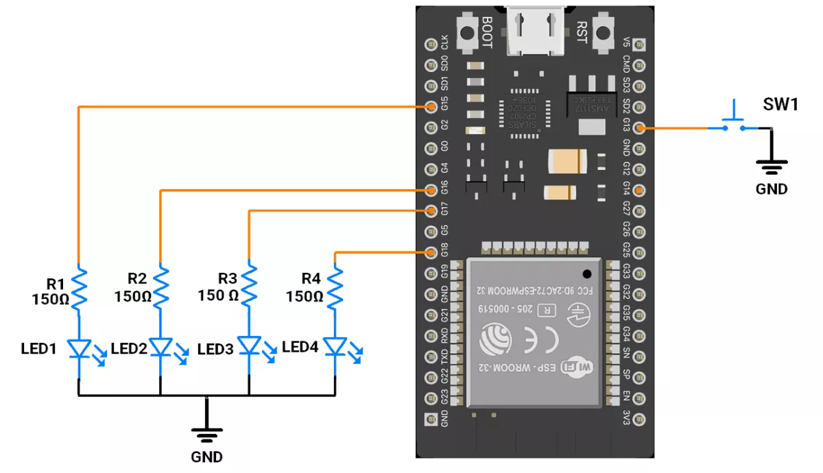
ESP32 Circuit Connection
- Interface 4 LEDs to GPIO pins 15, 16, 17, and 18.
- Push‑Button Interfacing (Internal Pull‑up Configuration)
- One terminal to GPIO 13.
- Other terminal to GND.
- In software, configure it as INPUT_PULLUP so the pin reads HIGH when idle and LOW when pressed.
Note: Avoid using GPIOs 34–39 for push-buttons while using ESP32 because they do not support pull-up/down resistors internally.
ESP32 Firmware Implementation
Code
//Harware configuration
const uint8_t led_pins[] = { 15, 16, 17, 18 };  // LEDs connected to pins
const uint8_t switch_pin = 13;                  // Pin for the switch

// Arrays related to LED Patterns
const uint8_t pattern_lengths[] = { 2, 2, 4, 2, 2 };
const uint8_t patterns[][4][4] = {
  { { 1, 1, 1, 1 }, { 0, 0, 0, 0 } },                                  // Pattern 0
  { { 1, 0, 1, 0 }, { 0, 1, 0, 1 } },                                  // Pattern 1
  { { 1, 0, 0, 0 }, { 0, 1, 0, 0 }, { 0, 0, 1, 0 }, { 0, 0, 0, 1 } },  // Pattern 2
  { { 1, 1, 0, 0 }, { 0, 0, 1, 1 } },                                  // Pattern 3
  { { 1, 0, 0, 1 }, { 0, 1, 1, 0 } }                                   // Pattern 4
};

bool flag_check = 1;                   // Controls the execution of the current pattern
uint8_t pattern_index = 0;             // Current pattern index
uint8_t debounce_delay = 50;           // Debounce delay in milliseconds
bool last_button_state = 1;            // Previous button state (1: not pressed, 0: pressed)
bool current_button_state = 1;         // Current button state
unsigned long last_debounce_time = 0;  // Timestamp of the last button state change

void setup() {

  for (uint8_t i = 0; i < 4; i++) {
    pinMode(led_pins[i], OUTPUT);
  }

  pinMode(switch_pin, INPUT_PULLUP);
}

void loop() {
  // Execute the selected pattern
  while (flag_check) {
    // Iterate through each step of the current pattern
    for (uint8_t j = 0; j < pattern_lengths[pattern_index]; j++) {
      set_leds(patterns[pattern_index][j]);       // Set LEDs for the current step
      flag_check = delay_with_button_check(500);  // Wait 500 ms with button check
      if (!flag_check) break;                     // Exit if the button is pressed
    }
    if (!flag_check) break;  // Exit the pattern loop if the button is pressed
  }
  flag_check = 1;  // Reset flag after pattern completion
}


// Checks if the button is pressed and debounced.

bool is_debounced_press(uint8_t button_pin) {
  bool reading = digitalRead(button_pin);

  // If the button state has changed, reset the debounce timer
  if (reading != last_button_state) {
    last_debounce_time = millis();
  }
  last_button_state = reading;
  // If the button state is stable for more than 50 msec the debounce delay, update the state.
  if ((millis() - last_debounce_time) > debounce_delay) {
    if (reading != current_button_state) {
      current_button_state = reading;

      // Return true if the button is pressed (LOW state)
      if (current_button_state == 0) {
        return true;  // valid press detected
      }
    }
  }
  return false;  // No valid press detected
}


// Implements a delay while checking for button press.

bool delay_with_button_check(unsigned long delay_duration) {
  unsigned long delay_start_time = millis();  // Record the start time of the delay
  while ((millis() - delay_start_time) < delay_duration) {
    if (is_debounced_press(switch_pin)) {
      pattern_index = (pattern_index + 1) % 5;  // Cycle to the next pattern
      return false;
    }
  }
  return true;  // Continue executing the pattern
}

// Set the states of the LEDs
void set_leds(const uint8_t states[]) {
  for (uint8_t i = 0; i < 4; i++) {
    digitalWrite(led_pins[i], states[i]);
  }
}
Code Explanation
- LED pins: Stored in
led_pins[]array for easy control. - Pattern data: Stored in
patterns[][][]— each pattern has one or more LED states. - Pattern length array:
pattern_lengths[]tells how many steps each pattern has. - Pattern switching: Pressing the button increments
pattern_index(wraps around to 0 after 4). - Debouncing: Implemented in
is_debounced_press()to avoid false button detections. - Delay with button check:
delay_with_button_check()is a custom delay that waits for 500 ms per step, but also checks for a button press. - LED setting:
set_leds()updates all LEDs according to the current pattern step.
We are using the Arduino UNO development board and programming it using the Arduino IDE.
- Before uploading, make sure to select “Arduino UNO” as the board to ensure correct settings and compatibility.
We need to connect 4 LEDs and a push button to the Arduino UNO.
A push button is used to change LED patterns.
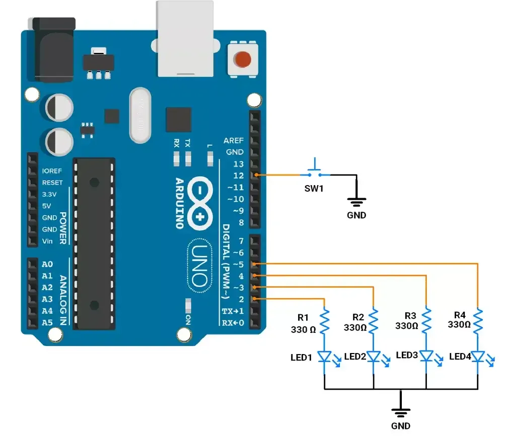
Arduino UNO Hardware Connection
- Connect 4 LEDs to pins 2,3,4, and 5, each with a 330 Ω resistor to GND.
- Connect a push button between pin 12 and GND, using Arduino’s internal pull-up.
Circuit Diagram
Arduino UNO Firmware Implementation
Code
const int led_pins[] = { 2, 3, 4, 5 };  // LEDs connected to pins
const int switch_pin = 12;              // Pin for the switch

// Arrays related to LED Patterns
const int pattern_lengths[] = { 2, 2, 4, 2, 2 };
const int patterns[][4][4] = {
  { { 1, 1, 1, 1 }, { 0, 0, 0, 0 } },                                  // Pattern 0
  { { 1, 0, 1, 0 }, { 0, 1, 0, 1 } },                                  // Pattern 1
  { { 1, 0, 0, 0 }, { 0, 1, 0, 0 }, { 0, 0, 1, 0 }, { 0, 0, 0, 1 } },  // Pattern 2
  { { 1, 1, 0, 0 }, { 0, 0, 1, 1 } },                                  // Pattern 3
  { { 1, 0, 0, 1 }, { 0, 1, 1, 0 } }                                   // Pattern 4
};

unsigned int flag_check = 1;           // Controls the execution of the current pattern
int pattern_index = 0;                 // Current pattern index
unsigned long debounce_delay = 50;     // Debounce delay in milliseconds
int last_button_state = 1;             // Previous button state (1: not pressed, 0: pressed)
int current_button_state = 1;          // Current button state
unsigned long last_debounce_time = 0;  // Timestamp of the last button state change

void setup() {

  for (int i = 0; i < 4; i++) {
    pinMode(led_pins[i], OUTPUT);
  }

  pinMode(switch_pin, INPUT_PULLUP);
}

void loop() {
  // Execute the selected pattern
  while (flag_check) {
    // Iterate through each step of the current pattern
    for (int j = 0; j < pattern_lengths[pattern_index]; j++) {
      set_leds(patterns[pattern_index][j]);       // Set LEDs for the current step
      flag_check = delay_with_button_check(500);  // Wait with button check
      if (!flag_check) break;                     // Exit if the button is pressed
    }
    if (!flag_check) break;  // Exit the pattern loop if the button is pressed
  }
  flag_check = 1;  // Reset flag after pattern completion
}


// Checks if the button is pressed and debounced.

bool is_debounced_press(int button_pin) {
  int reading = digitalRead(button_pin);

  // If the button state has changed, reset the debounce timer
  if (reading != last_button_state) {
    last_debounce_time = millis();
  }
  last_button_state = reading;
  // If the button state is stable for more than 50 msec the debounce delay, update the state.
  if ((millis() - last_debounce_time) > debounce_delay) {
    if (reading != current_button_state) {
      current_button_state = reading;

      // Return true if the button is pressed (LOW state)
      if (current_button_state == 0) {
        return true;  // valid press detected
      }
    }
  }
  return false;  // No valid press detected
}


// Implements a delay while checking for button press.

bool delay_with_button_check(long delay_duration) {
  long delay_start_time = millis();  // Record the start time of the delay
  while ((millis() - delay_start_time) < delay_duration) {
    if (is_debounced_press(switch_pin)) {
      pattern_index = (pattern_index + 1) % 5;  // Cycle to the next pattern
      return false;                             // Exit delay early
    }
  }
  return true;  // Continue executing the pattern
}

// Set the states of the LEDs
void set_leds(const int states[]) {
  for (int i = 0; i < 4; i++) {
    digitalWrite(led_pins[i], states[i]);
  }
}
Code Explanation
The program runs 5 LED patterns stored in arrays.
- Each pattern consists of multiple steps (ON/OFF states of 4 LEDs).
pattern_lengths[]tells how many steps each pattern has.
In the loop()
- The current pattern runs step-by-step with a 500 ms delay.
- During this time, the button is constantly checked (non-blocking delay).
- If button is pressed, exit the current pattern and move to the next pattern (using
pattern_index = (pattern_index + 1) % 5).
Button Handling (is_debounced_press())
- Reads button input.
- Waits 50 ms for stable state.
- Returns true only when a valid press is detected (LOW).
Responsive Delay (delay_with_button_check())
- Works like a custom delay()keeps checking the button during wait.
- If pressed, immediately switches to the next pattern, without waiting the full 500 ms.
LED Control (set_leds())
- Writes ON/OFF states of 4 LEDs for the current step.
Flags and Variables
flag_check→ Controls whether the pattern continues or breaks early when the button is pressed.pattern_index→ Keeps track of the current pattern (0–4, cycles back).
OUTPUT
LED and switch interfacing with Arduino UNO
