10. Logic Gate Implementation
Let’s understand the logic gates,
Truth tables of all gates give us a clear idea of how gates work.
| Input A | Input B | AND | OR | NAND | NOR |
|---|---|---|---|---|---|
| 0 | 0 | 0 | 0 | 1 | 1 |
| 0 | 1 | 0 | 1 | 1 | 0 |
| 1 | 0 | 0 | 1 | 1 | 0 |
| 1 | 1 | 1 | 1 | 0 | 0 |
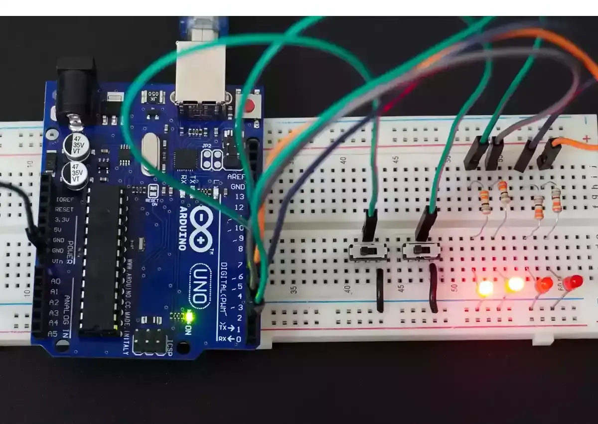
- So, to implement gates, we will use two slide switches and four LEDs. Each LED will show the output of the respective gate logic.
- We need to connect four LEDs to the microcontroller’s four GPIO pins.
- We need a proper resistor for each LED to limit the current flowing through them to 10mA.
Calculating the Resistor Value
To ensure a 10 mA current through the LED, we need to select an appropriate resistor based on the supply voltage.
Case 1: 5V Supply
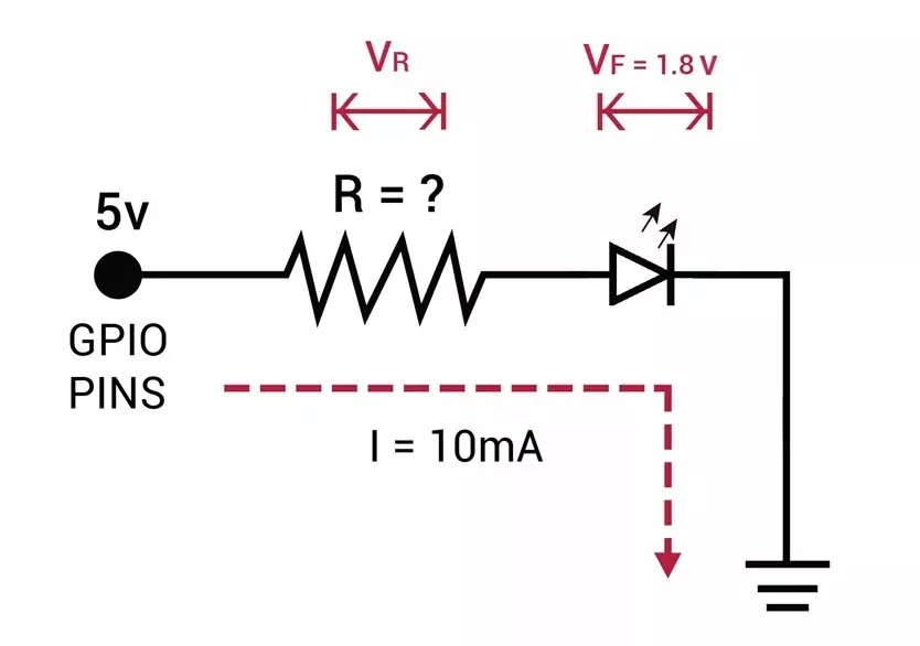
- LED forward voltage (Vf) = 1.8V (from datasheet)
- Voltage across resistor (VR) = Supply voltage – Vf = 5V – 1.8V = 3.2V
- Resistor value (R) = VR / I = 3.2V / 10 mA = 320 Ω
Standard resistor values near 320 Ω: 330 Ω or 300 Ω (whichever is available).
Similarly, Case 2: 3.3V Supply
- Voltage across resistor (VR) = 3.3V – 1.8V = 1.5V
- Resistor value (R) = 1.5V / 10 mA = 150 Ω
Standard resistor value: 150 Ω.
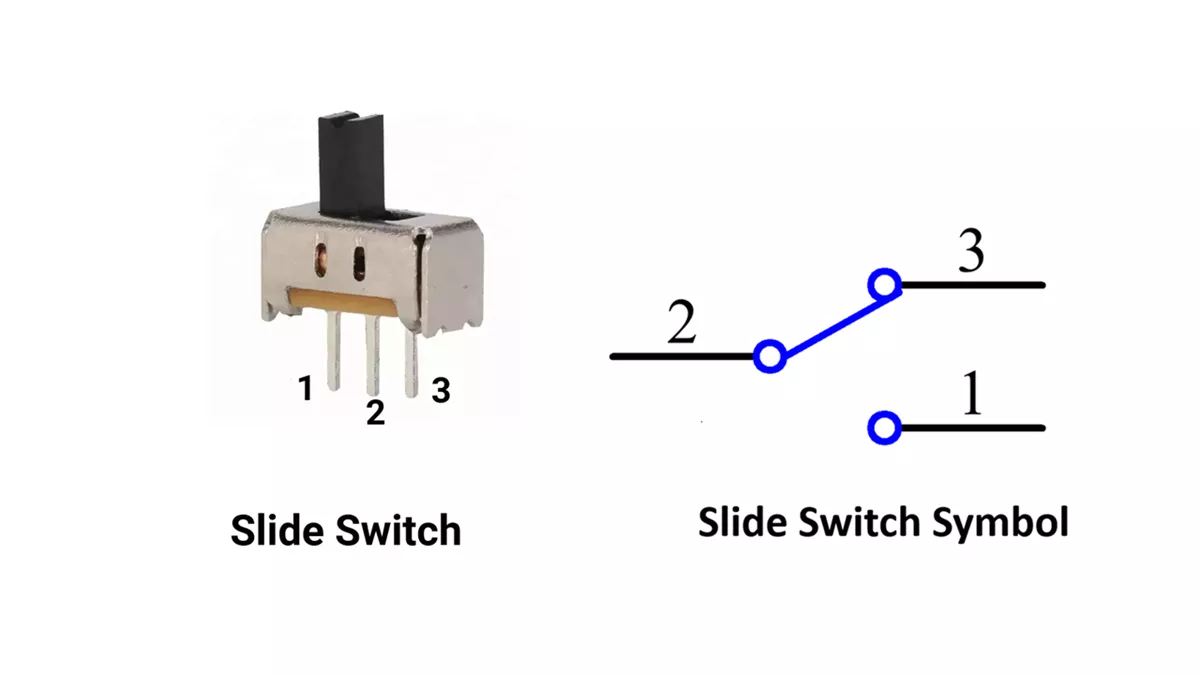
Slide Switch Connection:
- The slide switch has three terminals. Terminal 2 (Middle) is common. We can connect the first terminal to VCC and the third terminal to GROUND or vice versa.
- When the switch is at the left position, terminals 1 and 2 make contact. When the switch slides to the right, terminals 2 and 3 make contact.
So, by selecting a proper resistor, LED, and slide switch correctly, we can implement the task.
Below are the solutions to the given task using different microcontrollers
- STM32
- ESP32
- Arduino UNO
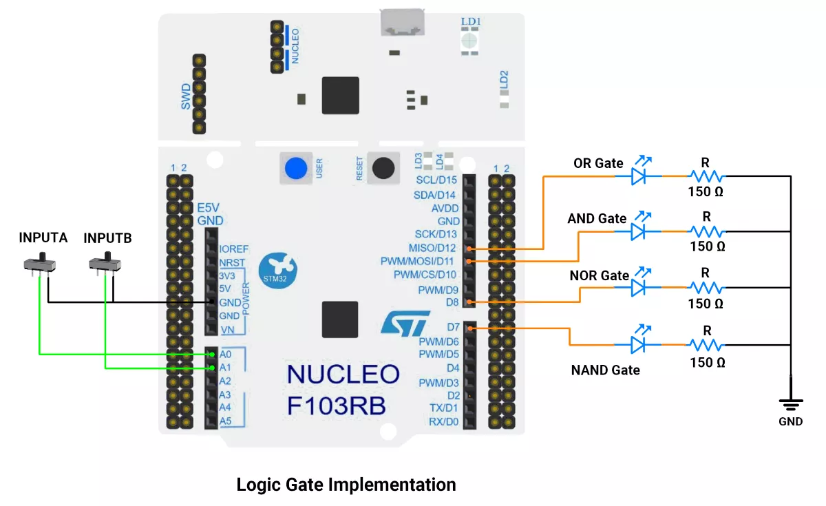
We’re using an STM32 NUCLEO-F103RB board, which runs at a 3.3V logic level.
Key Peripherals Used:
- GPIO: To connect a push-button switches and LEDs
STM32 Hardware Connection
- Switches: Connect the middle terminal to GPIO PA0 and PA1, one side terminal to to GND and another leave unconnected, and enable internal pull-up resistors in software.
- LEDs: Connect anodes of LED0(OR), LED1(AND), LED2(NOR), and LED3(NAND), to GPIO pins PA6, PA7, PA9, and PA8 respectively, and cathodes to ground through resistors.
Circuit Diagram
STM32 Firmware Implementation
Project Setup in STM32CubeIDE:
- Create a Project
- Open STM32CubeIDE and start a new project, select the NUCLEO-F103RB board.
- Basic Configuration (via CubeMX inside CubeIDE)
- Clock: Keep the default internal oscillator (no custom changes needed).
- GPIO Configuration:
- Switches: Set GPIO PA0 and PA2 as GPIO Input Pull-Up in the Pinout view (via STM32CubeMX, built into CubeIDE).
- LEDs: Set GPIO PA6, PA7, PA9, and PA8 as GPIO Output Push-Pull in the Pinout view (via STM32CubeMX, built into CubeIDE).
- Code Generation
- CubeMX will automatically generate all the startup code, including:
HAL_Init()→ Initializes the HAL library.SystemClock_Config()→ Configures system clock.MX_GPIO_Init()→ Configures GPIO pins
- This code sets up the hardware and prepares the project for firmware development, so we only need to add our application logic in the user code sections
- CubeMX will automatically generate all the startup code, including:
Code Snippets from main.c
GPIO Initialization
// In MX_GPIO_Init()

 /*Configure GPIO pins : PA0 PA1 */
 GPIO_InitStruct.Pin = GPIO_PIN_0|GPIO_PIN_1;
 GPIO_InitStruct.Mode = GPIO_MODE_INPUT;
 GPIO_InitStruct.Pull = GPIO_PULLUP;
 HAL_GPIO_Init(GPIOA, &GPIO_InitStruct);

/*Configure GPIO pins : LD2_Pin PA6 PA7 PA8 PA9 */
 GPIO_InitStruct.Pin = LD2_Pin|GPIO_PIN_6|GPIO_PIN_7|GPIO_PIN_8
                         |GPIO_PIN_9;
 GPIO_InitStruct.Mode = GPIO_MODE_OUTPUT_PP;
 GPIO_InitStruct.Pull = GPIO_NOPULL;
 GPIO_InitStruct.Speed = GPIO_SPEED_FREQ_LOW;
 HAL_GPIO_Init(GPIOA, &GPIO_InitStruct);
This configures pins PA0 and PA1 as digital inputs with an internal pull-up resistor enabled. The pull-up resistor ensures the input reads HIGH to prevent a floating input. And the pins PA6, PA7, PA8, and PA9 are configured as digital output pins using push-pull mode, which ensures they can actively drive the LEDs either HIGH or LOW with a strong and stable output.
Private Variable
uint8_t g_buttonState[2] = { 1, 1 }; // Store the state of each switch
In this array, the current state of the switches is stored.
Macros for Port and Pin
#define SWITCH0_PORT GPIOA
#define SWITCH0_PIN GPIO_PIN_0

#define SWITCH1_PORT GPIOA
#define SWITCH1_PIN GPIO_PIN_1

#define LED0_PORT GPIOA
#define LED0_PIN GPIO_PIN_6

#define LED1_PORT GPIOA
#define LED1_PIN GPIO_PIN_7

#define LED2_PORT GPIOA
#define LED2_PIN GPIO_PIN_9

#define LED3_PORT GPIOA
#define LED3_PIN GPIO_PIN_8
Defines easier-to-read names for the GPIO ports and pins of the switches and LEDs, improving code readability and maintainability.
Main Firmware Logic with Explanation
int main(void)
{
  /* Reset of all peripherals, Initializes the Flash interface and the Systick. */
  HAL_Init();

  /* Configure the system clock */
  SystemClock_Config();

  /* Initialize all configured peripherals */
  MX_GPIO_Init();
  MX_USART2_UART_Init();

  while (1) {
    // Variables to store the states of switches A and B
    uint8_t inputA = HAL_GPIO_ReadPin(SWITCH0_PORT, SWITCH0_PIN);
    uint8_t inputB = HAL_GPIO_ReadPin(SWITCH1_PORT, SWITCH1_PIN);

    //LEDs update only when inputs A or B change.
    if (inputA != g_buttonState[1] || inputB != g_buttonState[0]) {

      HAL_GPIO_WritePin(LED0_PORT, LED0_PIN, inputA | inputB);
      HAL_GPIO_WritePin(LED1_PORT, LED1_PIN, inputA & inputB);
      HAL_GPIO_WritePin(LED2_PORT, LED2_PIN, !(inputA | inputB));
      HAL_GPIO_WritePin(LED3_PORT, LED3_PIN, !(inputA & inputB));
      g_buttonState[1] = inputA;
      g_buttonState[0] = inputB;
    }
  }
}- Read PA0 (inputA) and PA1 (inputB).
- Update the LEDs only if the input state changes:
- LED0 (OR gate): lights if either switch is ON
(inputA | inputB). - LED1 (AND gate): lights if both switches are ON
(inputA & inputB). - LED2 (NOR gate): lights if both switches are OFF
(!(inputA | inputB)). - LED3 (NAND gate): lights when both switches are not ON
(!(inputA & inputB)).
- LED0 (OR gate): lights if either switch is ON
- Button state is stored and compared to prevent unnecessary updates.
Download Project
The complete STM32CubeIDE project (including .ioc configuration, main.c, and HAL files) is available here:
We are using the ESP32 DevKit v4 development board and programming it using the Arduino IDE.
- Before uploading, make sure to select “ESP32 Dev Module” as the board to ensure correct settings and compatibility.
Let's connect the two slide switches and four LEDs to the ESP32.
ESP32 Circuit Connection
Slide Switch Connection (3 terminals):
- Terminal 1 (Ground) → Connect to GND.
- Terminal 2 (Common) → Connect to GPIO pin (13 and 14) with internal pull‑up enabled in code.
- Terminal 3 → Leave unconnected.
LED Connections
- OR gate LED → GPIO 15
- AND gate LED → GPIO 16
- NOR gate LED → GPIO 17
- NAND gate LED → GPIO 18
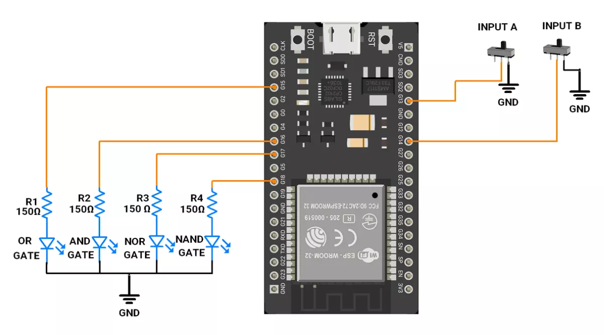
Use a 150Ω resistor in series with each LED to limit current to 10mA and protect the ESP32 pins.
ESP32 Firmware Implementation
Code
//updation = We can use internal pulldown resistor
uint8_t gate_leds[4] = { 15, 16, 17, 18 };  // Pins for the LEDs representing logic gates (OR, AND, NOR, NAND)
uint8_t switch_pins[2] = { 13, 14 };        // Pins for the switches (inputs A and B)

bool input_a = 1, input_b = 1;         // Variables to store the states of switches A and B
bool ButtonState[2] = { HIGH, HIGH };  // Store the state of each button

void setup() {
  // Configure gate LED pins as outputs
  for (uint8_t i = 0; i < 4; i++) {
    pinMode(gate_leds[i], OUTPUT);
  }

  // Configure switch pins as inputs
  for (uint8_t i = 0; i < 2; i++) {
    pinMode(switch_pins[i], INPUT_PULLUP);
  }
}


void loop() {

  input_a = digitalRead(switch_pins[1]);
  input_b = digitalRead(switch_pins[0]);

  //LEDs update only when inputs A or B change.
  if (input_a != ButtonState[1] || input_b != ButtonState[0]) {

    // Perform logic gate operations and update the corresponding LEDs state
    digitalWrite(gate_leds[0], input_a | input_b);     // OR operation
    digitalWrite(gate_leds[1], input_a & input_b);     // AND operation
    digitalWrite(gate_leds[2], !(input_a | input_b));  // NOR operation
    digitalWrite(gate_leds[3], !(input_a & input_b));  // NAND operation
    ButtonState[1] = input_a;
    ButtonState[0] = input_b;
  }
}
Code Explanation
The program simulates 4 basic logic gates (OR, AND, NOR, NAND) using LEDs.
Two push buttons act as inputs A and B.
Pin Setup
gate_leds[]→ 4 pins for LEDs, each representing a logic gate (OR, AND, NOR, NAND).switch_pins[]→ 2 pins for input switches (A and B).- INPUT_PULLUP is used → button reads HIGH when not pressed, LOW when pressed.
Variables
input_a,input_b→ store the current state of switches A and B.ButtonState[]→ stores the previous state of switches to detect changes.
setup()
- Configures all
gate_leds[]as OUTPUT. - Configures all
switch_pins[]as INPUT_PULLUP.
loop() Execution
- Read Switch Inputs
Reads states of switches A and B (inverted logic due to pull-up).input_a = digitalRead(switch_pins[1]);input_b = digitalRead(switch_pins[0]); - Check for Change
Only update LEDs if input A or B has changed → avoids unnecessary writes.
if (input_a != ButtonState[1] || input_b != ButtonState[0]) - Update Stored State
Saves new button states for the next loop cycle.ButtonState[1] = input_a;ButtonState[0] = input_b;
We are using the Arduino UNO development board and programming it using the Arduino IDE.
- Before uploading, make sure to select “Arduino UNO” as the board to ensure correct settings and compatibility.
To implement gates, we will interface 2 slide switches(with internal pull-up) and 4 LEDs to the Arduino UNO.
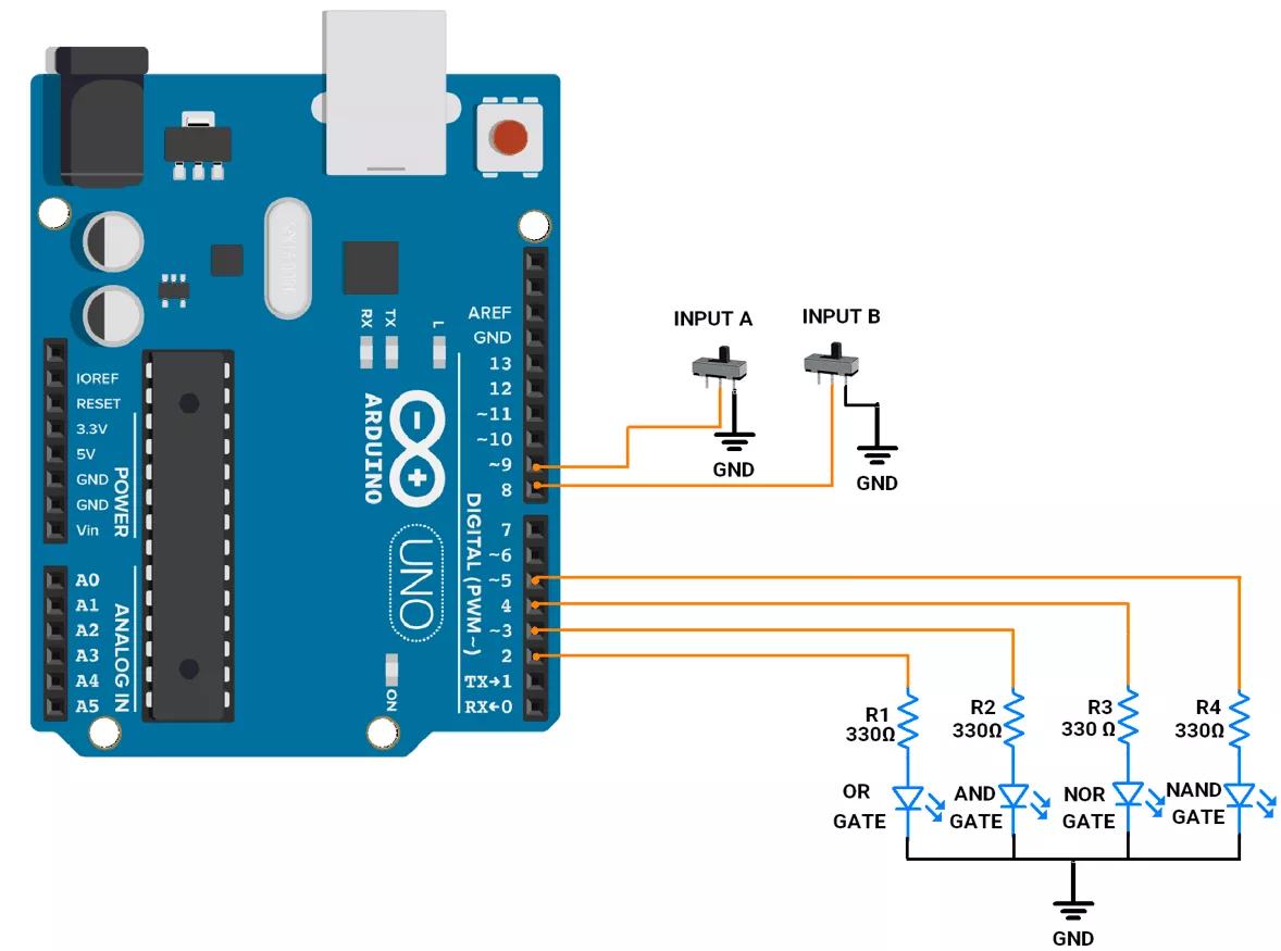
Arduino UNO Circuit Diagram
A slide switch has three terminals
- Terminal 1 (Ground): Connected to GND.
- Terminal 2 (Common): Connected to GPIO (8 and 9) with internal pull-up enabled.
- Terminal 3: Not connected.
LED interfacing
- OR LED → Connect to GPIO pin 2.
- AND LED → Connect to GPIO pin 3.
- NOR LED → Connect to GPIO pin 4.
- NAND LED → Connect to GPIO pin 5.
Arduino UNO Firmware Implementation
Code
Based on the slide switch state, we simply have to implement logic gates. Here, we don’t need to take care of debouncing, as it is only for a few milliseconds and won’t be visible in gate implementation or interfere with logic gate operation.
uint8_t gate_leds[4] = { 2, 3, 4, 5 };  // Pins for the LEDs representing logic gates (OR, AND, NOR, NAND)
uint8_t switch_pins[2] = { 8, 9 };      // Pins for the switches (inputs A and B)

uint8_t input_a = 1, input_b = 1;  // Variables to store the states of switches A and B

uint8_t ButtonState[2] = { HIGH, HIGH };      // Store the state of each button


void setup() {
  // Configure gate LED pins as outputs
  for (int i = 0; i < 4; i++) {
    pinMode(gate_leds[i], OUTPUT);
  }

  // Configure switch pins as inputs
  for (int i = 0; i < 2; i++) {
    pinMode(switch_pins[i], INPUT_PULLUP);
  }
}


void loop() {

    input_a = !digitalRead(switch_pins[1]);
    input_b = !digitalRead(switch_pins[0]);

  //LEDs update only when inputs A or B change.
  if ( input_a != ButtonState[1] || input_b != ButtonState[0]) {

    // Perform logic gate operations and update the corresponding LEDs state
    digitalWrite(gate_leds[0], input_a | input_b);     // OR operation
    digitalWrite(gate_leds[1], input_a & input_b);     // AND operation
    digitalWrite(gate_leds[2], !(input_a | input_b));  // NOR operation
    digitalWrite(gate_leds[3], !(input_a & input_b));  // NAND operation
    ButtonState[1] = input_a;
    ButtonState[0] = input_b;
  }

}
Code Explanation
- Input Handling
- Two switches (A, B) are connected with INPUT_PULLUP, so pressed = 0, released = 1.
- Their values are inverted (
!digitalRead()) to make pressed = 1, released = 0.
- Change Detection
- The program checks if either input has changed compared to the last state (
ButtonState). - This avoids unnecessary LED updates.
- The program checks if either input has changed compared to the last state (
So, two switches act as binary inputs, and four LEDs show real-time outputs of OR, AND, NOR, and NAND gates.
Output
Logic gate implementation with 4 LEDs and 2 slide switch.