58. Multi-Master interface with I2C 16x2-LCD
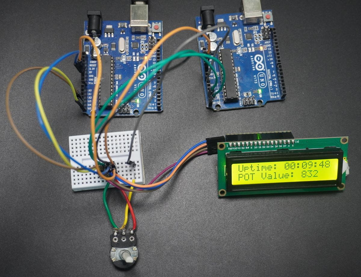
The task is to set up I²C communication between two master microcontrollers and a 16x2 LCD (slave) using the PCF8574 I²C module, enabling both masters to display their respective data on a shared LCD screen.
Requirements
- Master 1: Displays the system uptime (start time) on LCD line 1.
- Master 2: Reads the potentiometer’s ADC value and displays it on LCD line 2.
- Implement multi-master I²C communication to ensure both masters can transmit data to the LCD without interference.
- The LCD should continuously display Uptime and ADC Value from both masters in real-time.
Multi-Master I²C Concept
In a multi-master I²C system, multiple masters share the same SDA (data) and SCL (clock) lines.
Arbitration ensures that only one master controls the bus at a time:
- Each master checks if the bus is idle (SDA and SCL HIGH).
- During transmission, it monitors SDA.
- If a master sends HIGH but reads LOW, it loses arbitration and stops, allowing the winning master to continue.
This process of arbitration is automatically handled by hardware, while synchronisation keeps all devices aligned in timing — enabling reliable communication with shared peripherals like the LCD using minimal wiring.
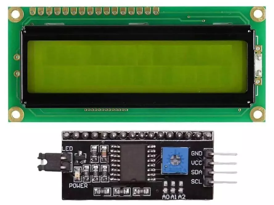
LCD16x2 with I²C Module (PCF8574)
- The PCF8574 I²C module makes it easy to connect an LCD16x2 display to a microcontroller using only two pins – SDA and SCL.
- It reduces GPIO usage from 6 (in 4-bit mode) to just 2 lines.
- The module also includes a contrast adjustment potentiometer and built-in pull-up resistors for SDA and SCL.
- It supports both 16x2 and 20x4 LCDs.
- Simply connect the module to the LCD and link SDA, SCL, VCC, and GND to the microcontroller.
LCD 4-Bit Communication (Working Principle)
In 4-bit mode, the LCD uses only D4–D7 data pins.
Each 8-bit instruction or data byte is sent in two 4-bit parts (high nibble first, then low).
- RS (Register Select): 0 = Command, 1 = Data
- RW (Read/Write): 0 = Write (usually fixed LOW)
- EN (Enable): A HIGH→LOW pulse latches each nibble.
- Command Register: Controls LCD (clear, set cursor, etc.)
- Data Register: Displays characters on the screen
- Before use, initialize the LCD with these commands:
0x33, 0x32, 0x28, 0x0C, 0x06, 0x01
Hardware Connection:
- Connect 5V and GND from any master to the LCD module.
- Connect the SDA and SCL of both masters and the LCD together.
- Enable internal or External pull-up resistors for SDA and SCL lines.
- Connect the potentiometer to Master 2’s ADC pin.
- Ensure a common GND across all devices.
Implementation Platforms:
This task will be implemented on the following microcontrollers:
- STM32
- ESP32
- Arduino UNO
We’re using an STM32 NUCLEO-F103RB board for both the masters, which operate at a 3.3V logic level.
To interface the STM32 with the I2C 16x2 LCD, we are using the custom library lcd_i2c.c and lcd_i2c.h, which are included in the project.
To understand the implementation in detail, download the project and explore these files.
Overview of LCD I²C Driver (lcd_i2c.c / lcd_i2c.h)
We developed this driver to interface a 16×2 HD44780 LCD with an STM32 microcontroller using the I²C communication protocol.
Instead of connecting the LCD directly to many GPIO pins, I used a PCF8574 I²C expander — this reduces wiring and uses only two pins (SCL & SDA).
How It Works
- The HD44780 LCD normally works in 4-bit parallel mode, but here we send data serially over I²C.
- The PCF8574 converts this serial data into the parallel signals required by the LCD.
- Each byte is split into two 4-bit nibbles and mapped to the PCF8574 pins as:
RS, RW, EN, Backlight, D4–D7. - Each nibble is sent twice by toggling EN (Enable) from 1 → 0, which tells the LCD to latch the data.
Initialization Flow
When you call lcd_init(), it performs the LCD startup sequence:
- Wake-up: Sends 0x30 three times
- 4-bit Mode: Sends 0x20 to switch mode
- Function Set: 0x28 → 2 lines, 5×8 font
- Clear Display: 0x01
- Entry Mode Set: 0x06 → cursor moves right automatically
- Display ON: 0x0C
The backlight turns ON by default. After this, the LCD is ready to display characters.
Data Transfer and Control
Data is sent using interrupt-based I²C (HAL_I2C_Master_Seq_Transmit_IT), so the MCU isn’t stuck waiting for transfers to finish.
- Each transfer is atomic → completed fully before releasing the I²C bus.
- Callbacks handle events and errors:
HAL_I2C_MasterTxCpltCallback()→ called when data is sentHAL_I2C_ErrorCallback()→ handles errors and can calllcd_recover_bus()to reset I²C if needed
This approach keeps communication fast, safe, and non-blocking.
Available Driver Functions
Category | Functions | Purpose |
|---|---|---|
Display |
| Display operations |
Backlight |
| Control LCD light |
Status & Recovery |
| Check errors & recover communication |
Integration & Configuration Notes
When using this driver in your STM32 project:
- Enable I²C1 peripheral with both event and error interrupts in NVIC.
- The default I²C 7-bit address for PCF8574 is 0x27 (you can change it).
- Use short
HAL_Delay()calls in the init and write functions — they ensure proper LCD timing.
Concept Summary
This driver:
- Converts I²C serial communication into LCD-compatible 4-bit parallel signals
- Uses interrupt-based I²C transfers for efficiency
- Completes each command atomically, preventing mid-transfer corruption
- Automatically recovers from I²C errors
- Provides a simple API for writing text and controlling the LCD
A) STM32 as an I²C Master 1 – Uptime display on LCD
Key Peripherals Used
- I²C1 – Used for I²C communication.
- USART2 – 115200 baud (8-N-1) for debug prints/status.
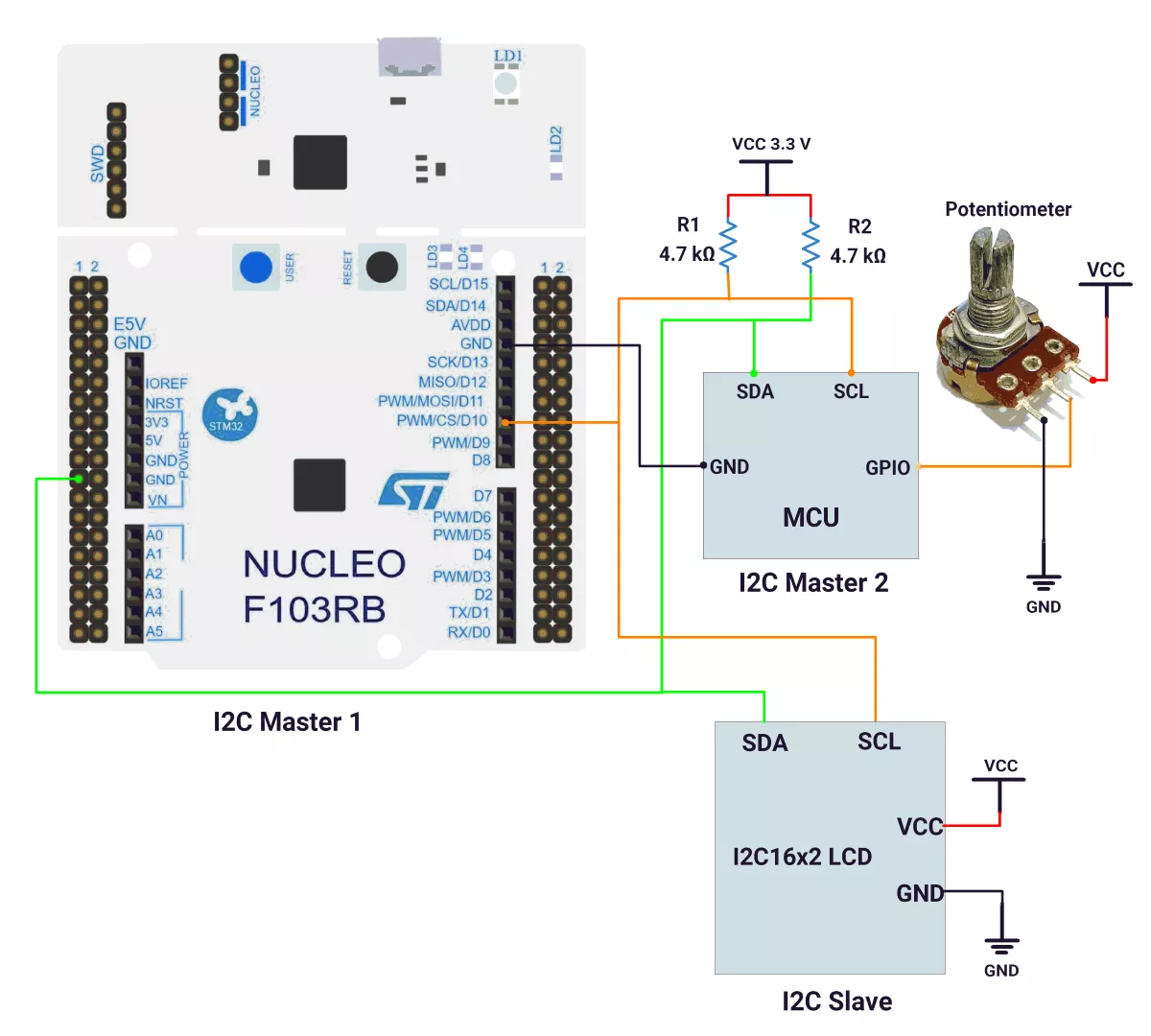
Hardware Connection
- I²C bus:
- PB6 (I²C1_SCL) → SCL of LCD and master 2
- PB7 (I²C1_SDA) → SDA of LCD and master 2
- Pull-ups: 4.7 kΩ from SDA to 3.3 V and SCL to 3.3 V (many LCD backpacks already include these; if present, external pull-ups are not required).
- Power/GND: LCD VCC → 3.3 V; GND shared with MCUs.
- UART to PC: On-board ST-Link VCP (PA2=TX, PA3=RX), micro-USB cable.
Circuit Diagram
Firmware Implementation
Project Setup in STM32CubeIDE
- Create a Project
Open STM32CubeIDE → New Project → NUCLEO-F103RB. - Basic Configuration (via CubeMX inside CubeIDE)
- Clock: Use default HSI + PLL (SystemClock_Config provided by Cube, typical SYSCLK ≈ 64 MHz).
- GPIO: Enable clocks for GPIOA, GPIOB, GPIOC, GPIOD.
- I²C1:
- Mode: I²C master, 100 kHz (Standard-mode).
- Pins: PB6 (SCL), PB7 (SDA), Open-Drain.
- NVIC: Enable I2C1 event and I2C1 error IRQs (the LCD driver uses interrupt-driven transfers).
- USART2: 115200, 8-N-1 for debugging (ST-Link VCP).
- Code Generation
CubeMX will automatically generate all the startup code, including:HAL_Init()– HAL and SysTick.SystemClock_Config()– HSI+PLL configuration.MX_GPIO_Init()– Port clocks.MX_I2C1_Init()– I²C setup.MX_USART2_UART_Init()– UART setup.
This code sets up the hardware and prepares the project for firmware development, so we only need to add our application logic in the user code sections
Code Snippets from main.c
I²C Initialization (MX_I2C1_Init)
hi2c1.Instance = I2C1;
hi2c1.Init.ClockSpeed = 100000;              // 100 kHz
hi2c1.Init.DutyCycle = I2C_DUTYCYCLE_2;
hi2c1.Init.AddressingMode = I2C_ADDRESSINGMODE_7BIT;
hi2c1.Init.OwnAddress1 = 0;
hi2c1.Init.NoStretchMode = I2C_NOSTRETCH_DISABLE;
if (HAL_I2C_Init(&hi2c1) != HAL_OK) { Error_Handler(); }
Initializes I²C1 as a 100 kHz 7-bit master, with clock stretching enabled on the master side.
User Sections
1. Includes
#include <string.h>
#include <stdio.h>
#include "lcd_i2c.h"- Adds standard libraries for string and formatted printing.
- Includes the custom I²C LCD driver header (lcd_i2c.h) to control the display via PCF8574.
2. Global Variables
I2C_HandleTypeDef hi2c1;
UART_HandleTypeDef huart2;

static char lcd_buffer[20];
static uint32_t lastTick = 0;- hi2c1 and huart2 are handles for I²C1 and UART2.
lcd_bufferstores text to send to the LCD.lastTicktracks the last time the LCD was updated.
3. Redirect printf() to UART
int __io_putchar(int ch)
{
    HAL_UART_Transmit(&huart2, (uint8_t *)&ch, 1, HAL_MAX_DELAY);
    return ch;
}- Sends every character printed with
printf()over UART2. - Enables serial debug output in a terminal (like PuTTY or Tera Term).
4. Display Uptime Function
static void display_uptime(void)
{
    uint32_t uptime = HAL_GetTick() / 1000U;
    uint8_t hours   = uptime / 3600U;
    uint8_t minutes = (uptime % 3600U) / 60U;
    uint8_t seconds = uptime % 60U;

    snprintf(lcd_buffer, sizeof(lcd_buffer), "Uptime:%03u:%02u:%02u",
             hours, minutes, seconds);
    lcd_write(0, 0, lcd_buffer);
}- Reads the system tick counter (milliseconds since startup).
- Converts it to HH:MM:SS format.
- Displays it on the LCD’s first row.
5. Main loop
int main(void)
{
    HAL_Init();                     // Start HAL and SysTick
    MX_GPIO_Init();                 // GPIO init (auto-gen)
    MX_USART2_UART_Init();          // UART init (auto-gen)
    MX_I2C1_Init();                 // I2C init (auto-gen)

    printf("STM32F103RB I2C LCD Master 1\r\n");

    // Initialize LCD via I2C
    lcd_i2c_attach(&hi2c1);
    if (lcd_init() == HAL_OK) {
        lcd_clear();
        lcd_backlight_on();
    } else {
        printf("LCD init failed\r\n");
    }

    // Main loop
    while (1)
    {
        uint32_t now = HAL_GetTick();
        if ((now - lastTick) >= 1000U) {
            lastTick = now;
            display_uptime();

            uint8_t err; lcd_state_t st;
            lcd_get_status(&err, &st);
            printf("Uptime:%lu s, I2C Errors:%u, State:%d\r\n",
                   now / 1000U, err, (int)st);

            if (st == LCD_STATE_ERROR) {
                printf("LCD error -> recovering bus...\r\n");
                lcd_recover_bus();
                HAL_Delay(1000);
            }
        }
        HAL_Delay(10); // Allow I²C sharing with other masters
    }
}
Explanation:
- Initializes HAL and peripherals.
- Attaches and initializes the LCD over I²C.
- Continuously updates the LCD once per second with system uptime.
- Prints debug data (uptime, I²C errors, state) via UART.
- If LCD communication fails, it attempts automatic I²C bus recovery.
- A small delay (10 ms) prevents bus lock in multi-master setups.
Explanation of Key HAL/Driver Functions Used
lcd_i2c_attach()– provides the I²C handle to the LCD driver.lcd_init()– runs the HD44780 4-bit init sequence via the PCF8574 (enable strobes, function set, clear, entry mode, display on).lcd_write(row, col, str)– sets DDRAM address and streams characters in a single I2C transaction to overcome an interrupt from another master.lcd_get_status()– reports driver state and I²C error counter.lcd_recover_bus()– re-inits I²C peripheral after error conditions (bus hung/NACK).
Note: The driver uses interrupt-driven I²C (HAL_I2C_Master_Seq_Transmit_IT) and implements HAL_I2C_MasterTxCpltCallback and HAL_I2C_ErrorCallback. Ensure I2C1 event/error interrupts are enabled in the NVIC.
Download Master 1 Project
The complete STM32CubeIDE project (including .ioc configuration, main.c, and HAL files) is available here:
📥 Download Project
B) STM32 as an I²C Master2 – Update Potentiometer ADC Value on LCD
Key Peripherals Used
- ADC1 – Reads analog voltage from the potentiometer on PA0 (channel 0).
- I²C1 – Used for I2C communication.
- USART2 – 115200 baud for debug prints/status.
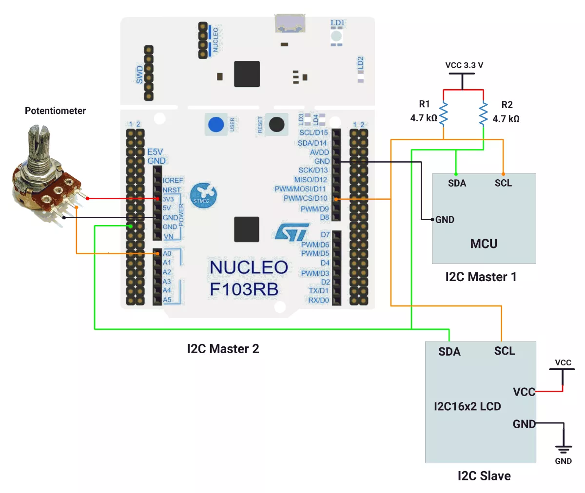
Hardware Connection
- Potentiometer:
- Middle wiper → PA0 (A0)
- Outer pins → 3.3 V and GND
- I²C bus:
- PB6 (I²C1_SCL) → SCL of LCD and master 1
- PB7 (I²C1_SDA) → SDA of LCD and master 1
- Pull-ups: 4.7 kΩ on SDA/SCL if not already on the backpack
- Common GND for MCUs, pot, and LCD
- USB to PC for power + VC
Circuit Diagram
Firmware Implementation
- Project Setup in STM32CubeIDE
- Create a Project
STM32CubeIDE → NUCLEO-F103RB.
- Create a Project
- Basic Configuration (via CubeMX inside CubeIDE)
- Clock: HSI + PLL (
SystemClock_Config,SYSCLK ≈ 64 MHz). - GPIO: Enable GPIOA/B/C/D clocks.
- ADC1:
- Resolution: 12-bit (0…4095).
- Channel:
ADC_CHANNEL_0(PA0). - Trigger: software (single conversion).
- Sample time: 239.5 cycles (stable readings from a pot).
- ADC clock: APB2/8 (as in your code via RCC_ADCPCLK2_DIV8).
- I²C1: I²C master, 100 kHz; enable I2C1 event/error IRQs.
- USART2: 115200, 8-N-1 (debug).
- Clock: HSI + PLL (
Code Generation
CubeMX will automatically generate all the startup code, including:
HAL_Init()– HAL and SysTick.SystemClock_Config()– HSI+PLL configuration.MX_GPIO_Init()– Port clocks.MX_I2C1_Init()– I²C setup.MX_ADC1_Init()– ADC setupMX_USART2_UART_Init()– UART setup.
This code sets up the hardware and prepares the project for firmware development, so we only need to add our application logic in the user code sections
Code Snippets from main.c
ADC Initialization (MX_ADC1_Init)
hadc1.Instance = ADC1;
hadc1.Init.ScanConvMode = ADC_SCAN_DISABLE;
hadc1.Init.ContinuousConvMode = DISABLE;
hadc1.Init.DiscontinuousConvMode = DISABLE;
hadc1.Init.ExternalTrigConv = ADC_SOFTWARE_START;
hadc1.Init.DataAlign = ADC_DATAALIGN_RIGHT;
hadc1.Init.NbrOfConversion = 1;
HAL_ADC_Init(&hadc1);

ADC_ChannelConfTypeDef sConfig = {0};
sConfig.Channel = ADC_CHANNEL_0;                         // PA0
sConfig.Rank = ADC_REGULAR_RANK_1;
sConfig.SamplingTime = ADC_SAMPLETIME_239CYCLES_5;       // robust sampling
HAL_ADC_ConfigChannel(&hadc1, &sConfig);
Configures ADC1 for single, software-triggered conversions on PA0, with long sample time for stable pot readings.
I²C Initialization (MX_I2C1_Init)
 hi2c1.Instance = I2C1;
hi2c1.Init.ClockSpeed = 100000;              // 100 kHz
hi2c1.Init.DutyCycle = I2C_DUTYCYCLE_2;
hi2c1.Init.AddressingMode = I2C_ADDRESSINGMODE_7BIT;
hi2c1.Init.OwnAddress1 = 0;
hi2c1.Init.NoStretchMode = I2C_NOSTRETCH_DISABLE;
if (HAL_I2C_Init(&hi2c1) != HAL_OK) { Error_Handler(); }
Initializes I²C1 as a 100 kHz 7-bit master, with clock stretching enabled on the master side.
User sections
1. Includes
#include <string.h>
#include <stdio.h>
#include "lcd_i2c.h"- Standard C headers for string and formatted I/O functions.
- lcd_i2c.h → Custom driver to control a 16×2 LCD via I²C (PCF8574 expander).
2. Global Variables
ADC_HandleTypeDef hadc1;
I2C_HandleTypeDef hi2c1;
UART_HandleTypeDef huart2;

static char lcd_buffer[20];
static uint32_t lastTick = 0;- hadc1 – ADC peripheral handle (for reading potentiometer voltage).
- hi2c1 – I²C handle (for LCD communication).
- huart2 – UART handle (for debug prints).
- lcd_buffer – Text buffer for LCD output.
- lastTick – Tracks last display update time.
3. Redirect printf() to UART
int __io_putchar(int ch)
{
    HAL_UART_Transmit(&huart2, (uint8_t *)&ch, 1, HAL_MAX_DELAY);
    return ch;
}
Redirects all printf() output to USART2, so logs appear on a serial terminal (115200 baud).
Useful for debugging and monitoring ADC readings.
4. Display ADC Value Function
static void display_ADC_value(void)
{
    HAL_ADC_Start(&hadc1);                         // Start conversion
    HAL_ADC_PollForConversion(&hadc1, 20);         // Wait (timeout 20 ms)
    uint16_t adcValue = HAL_ADC_GetValue(&hadc1);  // Read 12-bit result

    snprintf(lcd_buffer, sizeof(lcd_buffer),
             "POT Value:%04d  ", adcValue);
    lcd_write(1, 0, lcd_buffer);                   // Show on LCD (row 1)
}
What it does:
- Starts an ADC conversion on the configured channel (connected to the potentiometer).
- Waits until conversion completes.
- Reads the 12-bit digital value (0–4095).
- Formats and displays it on the second line of the LCD.
5. Main Loop
int main(void)
{
    HAL_Init();                // HAL & SysTick setup
    MX_GPIO_Init();
    MX_USART2_UART_Init();
    MX_ADC1_Init();
    MX_I2C1_Init();

    printf("STM32F103RB I2C LCD Master 2\r\n");

    // LCD Initialization
    lcd_i2c_attach(&hi2c1);
    if (lcd_init() == HAL_OK) {
        lcd_clear();
        lcd_backlight_on();
    } else {
        printf("LCD init failed\r\n");
    }

    // Main loop
    while (1)
    {
        uint32_t now = HAL_GetTick();
        if ((now - lastTick) >= 500U) {
            lastTick = now;

            display_ADC_value();      // Show updated ADC value

            uint8_t err; lcd_state_t st;
            lcd_get_status(&err, &st);
            printf("I2C Errors:%u, State:%d\r\n", err, (int)st);

            if (st == LCD_STATE_ERROR) {
                printf("LCD error -> recovering bus...\r\n");
                lcd_recover_bus();
                HAL_Delay(1000);
            }
        }
        HAL_Delay(10);   // Keeps I²C bus cooperative in multi-master setup
    }
    }
Explanation:
- Initializes HAL, GPIO, UART2, ADC1, and I²C1.
- Attaches and initializes the LCD through the I²C driver.
- Every 500 ms, it:
- Reads the ADC value from the potentiometer.
- Updates the LCD with the new reading.
- Reports I²C error count and LCD state via UART.
- Recovers the I²C bus if communication fails.
- Adds a small
HAL_Delay(10)between iterations for stable multi-master communication.
Explanation of Key HAL/Driver Functions Used
- ADC path:
HAL_ADC_Start()→ begins a single conversion.HAL_ADC_PollForConversion()→ waits (blocking) for completion.HAL_ADC_GetValue()→ reads right-aligned 12-bit value (0–4095).
- LCD/I²C path: same APIs as Master-1. Update period is 500 ms for responsive UI.
Download Master 2 Project
The complete STM32CubeIDE project (including .ioc configuration, main.c, and HAL files) is available here:
📥 Download Project
We are using the ESP32 DevKitC v4 development board and programming it using the Arduino IDE.
- Before uploading, make sure to select “ESP32 Dev Module” as the board to ensure correct settings and compatibility.
In both ESP32 master and slave codes, the Wire.h library is used for I²C communication.
Default I²C Pins Of ESP32
By default, the ESP32 Arduino core assigns:
- SDA → GPIO21
- SCL → GPIO22
In the given task, we used the default I²C Pins.
Solution of the given task:
- ESP32 as Master 1
- ESP32 as Master 2
A) ESP32 as Master 1
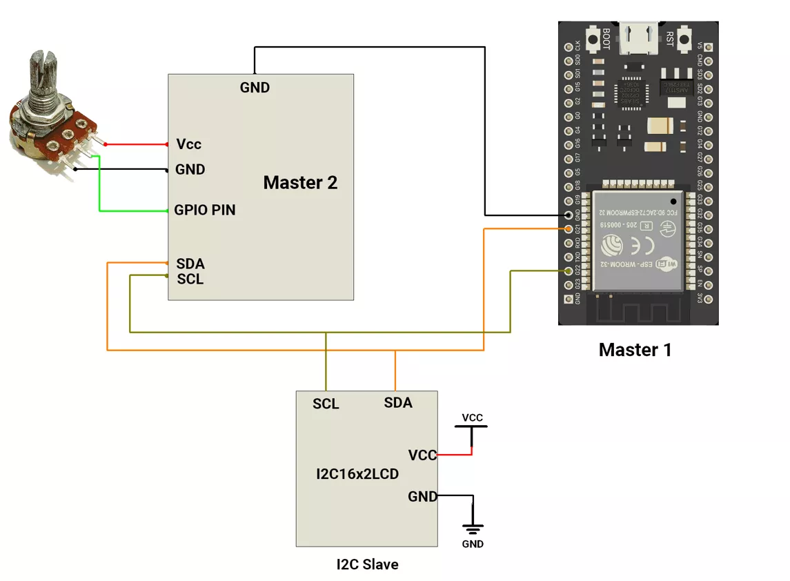
Circuit Connection
- Connect the LCD’s I²C module to Master 1 using:
- SDA → GPIO21
- SCL → GPIO22
- Connect Master 2’s SDA and SCL lines in parallel with Master 1’s SDA and SCL lines and the LCD.
This creates a shared I²C bus, allowing both masters to communicate with the same LCD using only two wires (SDA and SCL) along with common VCC and GND.
Circuit Diagram
Firmware Implementation
Code
#include <Wire.h>
#include <Arduino.h>

/*User Configuration*/
#define LCD_I2C_ADDRESS  0x27        // I2C address of the LCD module
#define LCD_I2C_FREQ_HZ  100000      // I2C communication frequency (100kHz)
#define LCD_SDA_PIN      21          // ESP32 SDA pin
#define LCD_SCL_PIN      22          // ESP32 SCL pin

#define LCD_DELAY_MS(ms) delay(ms)              // Macro for millisecond delay
#define LCD_DELAY_US(us) delayMicroseconds(us)  // Macro for microsecond delay

/*LCD Bit Mapping
   PCF8574 → LCD pin connection (typical):
   P0 = RS, P1 = RW, P2 = EN, P3 = Backlight, P4–P7 = D4–D7
*/
#define LCD_EN           0x04U  // Enable bit (latch signal)
#define LCD_RW           0x02U  // Read/Write bit (0 = Write)
#define LCD_RS           0x01U  // Register Select (0 = Command, 1 = Data)
#define LCD_BACKLIGHT    0x08U  // Backlight control bit

static uint8_t s_backlight = LCD_BACKLIGHT;     // Keeps LCD backlight ON

//Prepares 4-byte sequence to send 8-bit data (split into two 4-bit nibbles).
//Each nibble is latched using EN HIGH→LOW transition.
static int build_nibble_seq(uint8_t data, uint8_t control, uint8_t *out) {
  out[0] = s_backlight | control | (data & 0xF0) | LCD_EN;          // High nibble + EN=1
  out[1] = s_backlight | control | (data & 0xF0);                   // High nibble + EN=0
  out[2] = s_backlight | control | ((data << 4) & 0xF0) | LCD_EN;   // Low nibble + EN=1
  out[3] = s_backlight | control | ((data << 4) & 0xF0);            // Low nibble + EN=0
  return 4; // Returns number of bytes generated
}

//Sends a command byte to the LCD (RS=0).
static void lcd_command(uint8_t cmd) {
  uint8_t seq[4];
  build_nibble_seq(cmd, 0, seq);
  Wire.beginTransmission(LCD_I2C_ADDRESS);
  Wire.write(seq, 4);
  Wire.endTransmission();
}

//Sends data (a display character) to the LCD (RS=1).
static void lcd_data(uint8_t data) {
  uint8_t seq[4];
  build_nibble_seq(data, LCD_RS, seq);
  Wire.beginTransmission(LCD_I2C_ADDRESS);
  Wire.write(seq, 4);
  Wire.endTransmission();
  LCD_DELAY_US(50); // Short delay for LCD to process
}

//LCD Initialization
//Initializes the LCD in 4-bit mode as per HD44780 datasheet sequence.
void lcd_init() {
  Wire.begin(LCD_SDA_PIN, LCD_SCL_PIN);   // Initialize I2C bus
  Wire.setClock(LCD_I2C_FREQ_HZ);         // Set I2C speed

  // Turn ON backlight
  Wire.beginTransmission(LCD_I2C_ADDRESS);
  Wire.write(s_backlight);
  Wire.endTransmission();

  LCD_DELAY_MS(50); // Wait for LCD power stabilization

  // Initialization sequence for 4-bit interface
  lcd_command(0x30);
  LCD_DELAY_MS(5);
  lcd_command(0x30);
  LCD_DELAY_US(150);
  lcd_command(0x30);
  LCD_DELAY_US(150);
  lcd_command(0x20); // Set 4-bit mode
  LCD_DELAY_MS(5);

  // Function set: 4-bit, 2 lines, 5x8 font
  lcd_command(0x28);
  LCD_DELAY_US(50);

  // Display control: display OFF
  lcd_command(0x08);
  LCD_DELAY_US(50);

  // Clear display
  lcd_command(0x01);
  LCD_DELAY_MS(3);

  // Entry mode: increment cursor
  lcd_command(0x06);
  LCD_DELAY_US(50);

  // Display ON, cursor OFF
  lcd_command(0x0C);
  LCD_DELAY_US(50);
}

//LCD Write Function
void lcd_write(uint8_t row, uint8_t col, const char *str) {
  if (!str) return; // Skip if string is null

  // LCD DDRAM starting addresses for each line
  static const uint8_t row_addr[] = { 0x00, 0x40, 0x14, 0x54 };
  uint8_t addr = 0x80 | (col + row_addr[row]); // Set cursor position

  // Build full I2C transmission buffer (cursor + text)
  uint8_t txbuf[4 + 4 * 80];
  int idx = 0;

  // Add cursor set command (RS=0)
  idx += build_nibble_seq(addr, 0, &txbuf[idx]);

  // Add character data (RS=1)
  for (size_t i = 0; str[i] && i < 80; i++) {
    idx += build_nibble_seq(str[i], LCD_RS, &txbuf[idx]);
  }

  // Transmit entire buffer in one I2C transaction
  Wire.beginTransmission(LCD_I2C_ADDRESS);
  Wire.write(txbuf, idx);
  Wire.endTransmission(); // Send STOP condition
}

//Clears the LCD display and resets cursor position.
void lcd_clear() {
  lcd_command(0x01);
  LCD_DELAY_MS(3);
}

void setup() {
  delay(1000);  // Allow power and peripherals to stabilize
  Serial.begin(115200);
  Serial.println("Initializing LCD...");

  lcd_init();   // Initialize LCD
  lcd_clear();  // Clear display
}


void loop() {
  static unsigned long lastUpdate = 0;

  // Update every 1 second
  if (millis() - lastUpdate > 1000) {
    lastUpdate = millis();

    // Calculate uptime in hours, minutes, and seconds
    unsigned long timeSec = millis() / 1000;
    uint8_t hours   = timeSec / 3600;
    uint8_t minutes = (timeSec % 3600) / 60;
    uint8_t seconds = timeSec % 60;

    // Format uptime text
    char buff[20];
    sprintf(buff, "Uptime:%03d:%02d:%02d", hours, minutes, seconds);

    // Display uptime on LCD line 1
    lcd_write(0, 0, buff);
  }
}
Code Explanation
Wire.begin(LCD_SDA_PIN, LCD_SCL_PIN)
Initializes the ESP32 as an I²C master, defining the pins used for I²C communication:- SDA → GPIO 21
- SCL → GPIO 22
This allows the ESP32 to communicate with the PCF8574 I²C expander that drives the LCD.
Wire.setClock(LCD_I2C_FREQ_HZ)
Sets the I²C communication frequency to 100 kHz (standard mode).
This ensures stable and reliable data transfer between the ESP32 and the LCD module.- LCD Initialization Sequence:
The LCD must be properly initialized to enter 4-bit mode for communication.
The sequence below follows the HD44780 controller initialization process:
Step | Command |
|---|---|
|
|
|
|
|
|
|
|
|
|
|
|
|
|
These commands ensure the LCD is correctly set up to receive 4-bit data via I²C.
- Data Transmission Logic:
- The
build_nibble_seq()function splits each 8-bit command or character into two 4-bit parts (high nibble and low nibble). - Each nibble is sent separately, with an Enable (EN) pulse (HIGH → LOW) to latch it into the LCD.
- The RS (Register Select) bit decides the purpose of the data:
- RS = 0 → Command (instructions like clear, cursor move).
- RS = 1 → Data (character to display).
- This is required because the LCD is operating in 4-bit mode, not 8-bit parallel mode.
lcd_command()andlcd_data()lcd_command(cmd)sends instruction bytes (like clear screen, set mode).lcd_data(data)sends printable character data to the display.
Both useWire.beginTransmission()→Wire.write()→Wire.endTransmission()for I²C data transfer.
- The
- Cursor Positioning (DDRAM Addressing):
The LCD has specific memory addresses (DDRAM) for each line.
Before writing text, the cursor must be moved to the correct position:- Line 1 → 0x80 + column
- Line 2 → 0xC0 + column
- Line 3 → 0x94 + column (20x4 LCD only)
Line 4 → 0xD4 + column (20x4 LCD only)
In the code, this is calculated as:
uint8_t addr = 0x80 | (col + row_addr[row]);
The cursor is set before displaying the formatted uptime text.
lcd_write(row, col, str)- Positions the cursor to the specified row and column.
- Converts the text string into I²C-compatible data using
build_nibble_seq(). - The cursor position and entire string are sent together in a single I²C transaction.
- This ensures the transfer is atomic, preventing interruption or bus takeover by another I²C master
lcd_clear()
Clears the LCD using command 0x01 and resets the cursor to the top-left corner.- Uptime Calculation and Display:
The program continuously calculates system uptime using millis():unsigned long timeSec = millis() / 1000;uint8_t hours = timeSec / 3600;uint8_t minutes = (timeSec % 3600) / 60;uint8_t seconds = timeSec % 60;millis()counts milliseconds since the ESP32 started running.- These values are formatted into HHH:MM:SS using sprintf():
sprintf(buff, "Uptime:%03d:%02d:%02d", hours, minutes, seconds);
- Display Update Logic:
- The uptime display is refreshed once every second using:
if (millis() - lastUpdate > 1000) - After every update, the formatted uptime string is printed on LCD line 1:
lcd_write(0, 0, buff);
- The uptime display is refreshed once every second using:
- setup()
- Waits for power stabilisation (1 second).
- Starts serial communication for debugging.
- Initializes the LCD and clears the screen using
lcd_init()andlcd_clear().
- loop()
- Runs continuously:
- Calculates uptime every second.
- Updates LCD with the formatted uptime string on line 1.
B) ESP32 as Master 2
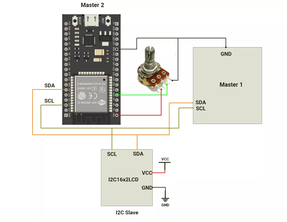
Circuit Connection
- Connect the LCD’s I²C module to Master 2 using:
- SDA → GPIO21
- SCL → GPIO22
- Connect Master 1’s SDA and SCL lines in parallel with Master 2’s SDA and SCL lines and the LCD.
This creates a shared I²C bus, allowing both masters to communicate with the same LCD using only two wires (SDA and SCL) along with common VCC and GND.
Circuit Connection
Firmware Implementation
Code
#include <Wire.h>
#include <Arduino.h>

/*User Configuration*/
#define LCD_I2C_ADDRESS  0x27        // I2C address of LCD (PCF8574 module)
#define LCD_I2C_FREQ_HZ  100000      // I2C bus frequency (100 kHz standard mode)
#define LCD_SDA_PIN      21          // ESP32 SDA pin
#define LCD_SCL_PIN      22          // ESP32 SCL pin
#define ADC_PIN          34          // Analog input pin connected to potentiometer

#define LCD_DELAY_MS(ms) delay(ms)              // Delay in milliseconds
#define LCD_DELAY_US(us) delayMicroseconds(us)  // Delay in microseconds

/*LCD Bit Mapping
   PCF8574 pin → LCD pin:
   P0 = RS, P1 = RW, P2 = EN, P3 = Backlight, P4–P7 = D4–D7
*/
#define LCD_EN           0x04U  // Enable bit (latch trigger)
#define LCD_RW           0x02U  // Read/Write bit (0 = Write)
#define LCD_RS           0x01U  // Register Select (0 = Command, 1 = Data)
#define LCD_BACKLIGHT    0x08U  // Backlight control bit

static uint8_t s_backlight = LCD_BACKLIGHT;  // Keep backlight ON

//Splits an 8-bit value into two 4-bit nibbles and prepares
//the 4-step sequence needed to latch both nibbles using EN pulses.
static int build_nibble_seq(uint8_t data, uint8_t control, uint8_t *out) {
  out[0] = s_backlight | control | (data & 0xF0) | LCD_EN;          // High nibble + EN=1
  out[1] = s_backlight | control | (data & 0xF0);                   // High nibble + EN=0
  out[2] = s_backlight | control | ((data << 4) & 0xF0) | LCD_EN;   // Low nibble + EN=1
  out[3] = s_backlight | control | ((data << 4) & 0xF0);            // Low nibble + EN=0
  return 4; // Returns total 4 bytes created
}

//Sends a command byte (RS=0) to the LCD.
static void lcd_command(uint8_t cmd) {
  uint8_t seq[4];
  build_nibble_seq(cmd, 0, seq);
  Wire.beginTransmission(LCD_I2C_ADDRESS);
  Wire.write(seq, 4);
  Wire.endTransmission();
}

//Sends a single data byte (RS=1) to the LCD.
static void lcd_data(uint8_t data) {
  uint8_t seq[4];
  build_nibble_seq(data, LCD_RS, seq);
  Wire.beginTransmission(LCD_I2C_ADDRESS);
  Wire.write(seq, 4);
  Wire.endTransmission();
  LCD_DELAY_US(50); // Short delay for LCD to process data
}

// LCD Initialization
void lcd_init() {
  Wire.begin(LCD_SDA_PIN, LCD_SCL_PIN);   // Start I2C with defined SDA/SCL
  Wire.setClock(LCD_I2C_FREQ_HZ);         // Set I2C clock

  // Turn on LCD backlight
  Wire.beginTransmission(LCD_I2C_ADDRESS);
  Wire.write(s_backlight);
  Wire.endTransmission();

  LCD_DELAY_MS(50); // Wait for LCD power-up

  // Initialization sequence for 4-bit operation
  lcd_command(0x30);
  LCD_DELAY_MS(5);
  lcd_command(0x30);
  LCD_DELAY_US(150);
  lcd_command(0x30);
  LCD_DELAY_US(150);
  lcd_command(0x20);  // Switch to 4-bit mode
  LCD_DELAY_MS(5);

  // Function set: 4-bit mode, 2-line display, 5x8 font
  lcd_command(0x28);
  LCD_DELAY_US(50);

  // Display control: display OFF
  lcd_command(0x08);
  LCD_DELAY_US(50);

  // Clear display
  lcd_command(0x01);
  LCD_DELAY_MS(3);

  // Entry mode: increment cursor, no shift
  lcd_command(0x06);
  LCD_DELAY_US(50);

  // Display ON, cursor OFF
  lcd_command(0x0C);
  LCD_DELAY_US(50);
}

//LCD Write Function
void lcd_write(uint8_t row, uint8_t col, const char *str) {
  if (!str)return; // Exit if string is null

  // LCD DDRAM starting addresses for 4 lines
  static const uint8_t row_addr[] = {0x00, 0x40, 0x14, 0x54};
  uint8_t addr = 0x80 | (col + row_addr[row]); // Set cursor address

  // Create transmission buffer (cursor set + string data)
  uint8_t txbuf[4 + 4 * 80];
  int idx = 0;

  // Add cursor set command
  idx += build_nibble_seq(addr, 0, &txbuf[idx]);

  // Add each character (data)
  for (size_t i = 0; str[i] && i < 80; i++) {
    idx += build_nibble_seq(str[i], LCD_RS, &txbuf[idx]);
  }

  // Send entire buffer in one I2C transmission
  Wire.beginTransmission(LCD_I2C_ADDRESS);
  Wire.write(txbuf, idx);
  Wire.endTransmission(); // Stop condition
}

//Clears the LCD screen and resets cursor position.
void lcd_clear() {
  lcd_command(0x01);
  LCD_DELAY_MS(3);
}

void setup() {
  delay(1000);                       // Allow system to stabilize
  Serial.begin(115200);
  Serial.println("Initializing LCD...");

  lcd_init();                        // Initialize LCD
  lcd_clear();                       // Clear screen before start
}

void loop() {
  static unsigned long lastUpdate = 0;

  // Update display every 1 second
  if (millis() - lastUpdate > 1000) {
    lastUpdate = millis();

    uint16_t adcValue = analogRead(ADC_PIN);  // Read potentiometer ADC value

    char buff[20];
    sprintf(buff, "POT Value: %04d", adcValue);  // Format ADC value string

    lcd_write(1, 0, buff);  // Display on line 2 (row index = 1)
  }
}
Code Explanation
Wire.begin(LCD_SDA_PIN, LCD_SCL_PIN)
Initializes the ESP32 as an I²C master and defines the SDA (21) and SCL (22) pins used for communication with the LCD module.
The ESP32 allows you to assign custom I²C pins.Wire.setClock(LCD_I2C_FREQ_HZ)
Sets the I²C communication speed to 100 kHz (standard mode).
This ensures reliable data transfer between the ESP32 and the PCF8574 I²C expander connected to the LCD.- LCD Initialization Sequence:
The LCD is not ready immediately after power-up, so a specific set of commands are sent to configure it.
These follow the HD44780 controller’s initialization routine:lcd_command(0x30)(×3) → Ensures LCD is awake and in 8-bit mode (default).lcd_command(0x20)→ Switches LCD to 4-bit mode, reducing the number of data lines needed.lcd_command(0x28)→ Function Set: 4-bit mode, 2-line display, 5x8 font.lcd_command(0x08)→ Display OFF (temporary).lcd_command(0x01)→ Clear display.lcd_command(0x06)→ Auto-increment cursor after each character.lcd_command(0x0C)→ Display ON, cursor OFF.- These commands ensure that the LCD is fully reset and ready to display data properly.
- Data Transmission Logic:
- The function
build_nibble_seq()divides each 8-bit command or character into two 4-bit parts (nibbles). - Each nibble is latched into the LCD using an Enable (EN) pulse (HIGH → LOW).
- This is required because the LCD is operating in 4-bit mode.
- RS bit determines whether the data being sent is:
- Command (RS=0) → controls LCD behavior (clear, set cursor, etc.)
- Data (RS=1) → writes characters to the display.
- Communication occurs through the PCF8574 I²C expander, which converts I²C signals into parallel control signals for the LCD.
- The function
- Cursor Positioning (DDRAM Addressing):
Before writing text, the cursor is positioned using the DDRAM address command:- Each LCD line starts at a unique base address:
- Line 1 → 0x00
- Line 2 → 0x40
- Line 3 → 0x14
- Line 4 → 0x54
- The code calculates the final address as:
uint8_t addr = 0x80 | (col + row_addr[row]);
- Each LCD line starts at a unique base address:
and sends it to the LCD as a command before displaying text.
lcd_write(row, col, str)- The cursor position and entire string are sent together in a single I²C transaction.
- This ensures the transfer is atomic, preventing interruption or bus takeover by another I²C master
- Each character is split into 4-bit nibbles using
build_nibble_seq()and sent sequentially to the LCD.
- ADC Reading:
- The ESP32 reads the potentiometer value from analog pin 34 using:
uint16_t adcValue = analogRead(ADC_PIN); - The ADC converts the analog voltage (0–3.3V) into a digital value (0–4095) since the ESP32 ADC is 12-bit.
- The value is formatted as a string:
sprintf(buff, "POT Value: %04d", adcValue);
- The ESP32 reads the potentiometer value from analog pin 34 using:
This ensures the display always shows 4 digits (e.g., POT Value: 0325).
- Display Update Logic:
- The display is updated once every second using:
if (millis() - lastUpdate > 1000) - Each second, the new ADC value is read and written to LCD line 2 (lcd_write(1, 0, buff)).
lcd_clear()
Clears the display (0x01 command) and resets the cursor to the top-left corner of the LCD.
- The display is updated once every second using:
- setup()
- Waits briefly for the system to stabilize (1 second).
- Initializes serial communication for debugging.
- Initializes the LCD via
lcd_init()and clears it before display begins.
- loop()
- Continuously reads the potentiometer value every 1 second.
- Displays the latest reading on line 2 of the LCD in the format:
POT Value: 0123
We are using the Arduino UNO development board and programming it using the Arduino IDE.
- Before uploading, make sure to select “Arduino UNO” as the board to ensure correct settings and compatibility.
In both Arduino UNO master and slave codes, the Wire.h library is used for I²C communication.
I²C Pins Of Arduino UNO
- SDA → A4
- SCL → A5
Solution of the given task
- Arduino UNO as Master 1
- Arduino UNO as Master 2
A) Arduino UNO as a Master 1
First, let's establish the hardware connection.
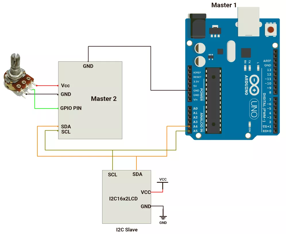
Hardware Connection
- Connect the LCD’s I²C module to Master 1 using:
- SDA → A4
- SCL → A5
- Connect Master 2’s SDA and SCL lines in parallel with Master 1’s SDA and SCL lines and the LCD.
This creates a shared I²C bus, allowing both masters to communicate with the same LCD using only two wires (SDA and SCL) along with common VCC and GND.
Circuit Diagram
Firmware Implementation
CODE
#include <Wire.h>
#include <Arduino.h>

#define LCD_I2C_ADDRESS 0x27  // I2C address of the LCD module

#define LCD_DELAY_MS(ms) delay(ms)              // Delay in milliseconds
#define LCD_DELAY_US(us) delayMicroseconds(us)  // Delay in microseconds

/*  LCD Bit Mapping
   PCF8574 (I2C chip) to LCD pins:
   P0 = RS, P1 = RW, P2 = EN, P3 = Backlight, P4–P7 = D4–D7
*/

#define LCD_EN 0x04U         // Enable pin (used for latching data)
#define LCD_RW 0x02U         // Read/Write (0 = Write)
#define LCD_RS 0x01U         // Register Select (0 = Command, 1 = Data)
#define LCD_BACKLIGHT 0x08U  // Backlight control

static uint8_t s_backlight = LCD_BACKLIGHT;  // Keep backlight ON

//Converts an 8-bit command or character into two 4-bit data transfers.
//Each 4-bit transfer (nibble) is latched using EN HIGH→LOW transitions.
static int build_nibble_seq(uint8_t data, uint8_t control, uint8_t *out) {
  out[0] = s_backlight | control | (data & 0xF0) | LCD_EN;         // High nibble + EN=1
  out[1] = s_backlight | control | (data & 0xF0);                  // High nibble + EN=0
  out[2] = s_backlight | control | ((data << 4) & 0xF0) | LCD_EN;  // Low nibble + EN=1
  out[3] = s_backlight | control | ((data << 4) & 0xF0);           // Low nibble + EN=0
  return 4;                                                        // Returns total 4 bytes to send
}


//Send a command to the LCD (RS=0).
static void lcd_command(uint8_t cmd) {
  uint8_t seq[4];
  build_nibble_seq(cmd, 0, seq);
  Wire.beginTransmission(LCD_I2C_ADDRESS);
  Wire.write(seq, 4);
  Wire.endTransmission();
}


//Send a single data byte to LCD (RS=1).

static void lcd_data(uint8_t data) {
  uint8_t seq[4];
  build_nibble_seq(data, LCD_RS, seq);
  Wire.beginTransmission(LCD_I2C_ADDRESS);
  Wire.write(seq, 4);
  Wire.endTransmission();
  LCD_DELAY_US(50);  // Short delay between characters
}

// LCD Initialization
void lcd_init() {
  Wire.begin();  // Initialize I2C communication
  Wire.beginTransmission(LCD_I2C_ADDRESS);
  Wire.write(s_backlight);  // Turn on backlight
  Wire.endTransmission();

  LCD_DELAY_MS(50);  // Wait for LCD power-up

  // LCD initialization sequence (4-bit mode)
  lcd_command(0x30);
  LCD_DELAY_MS(5);
  lcd_command(0x30);
  LCD_DELAY_US(150);
  lcd_command(0x30);
  LCD_DELAY_US(150);
  lcd_command(0x20);
  LCD_DELAY_MS(5);  // Set 4-bit mode

  // Function set: 4-bit, 2-line, 5x8 dots
  lcd_command(0x28);
  LCD_DELAY_US(50);

  // Display OFF
  lcd_command(0x08);
  LCD_DELAY_US(50);

  // Clear display
  lcd_command(0x01);
  LCD_DELAY_MS(3);

  // Entry mode: increment cursor
  lcd_command(0x06);
  LCD_DELAY_US(50);

  // Display ON, cursor OFF
  lcd_command(0x0C);
  LCD_DELAY_US(50);
}

/*  LCD Write String
*  Positions cursor and writes a full string to the LCD.
*/
void lcd_write(uint8_t row, uint8_t col, const char *str) {
  if (!str) return;  // Skip if no string provided

  // Calculate DDRAM address based on row and column
  uint8_t addr;
  switch (row) {
    case 0: addr = 0x80 + col; break;  // Line 1
    case 1: addr = 0xC0 + col; break;  // Line 2
    case 2: addr = 0x94 + col; break;  // Line 3 (for 20x4)
    case 3: addr = 0xD4 + col; break;  // Line 4 (for 20x4)
    default: addr = 0x80 + col; break;
  }

  uint8_t seq[4];

  // Send cursor position command (RS=0)
  Wire.beginTransmission(LCD_I2C_ADDRESS);
  build_nibble_seq(addr, 0x00U, seq);
  Wire.write(seq, 4);
  Wire.endTransmission(false);  // Keep bus active

  // Send characters (RS=1)
  size_t len = strlen(str);
  for (size_t i = 0; i < len; i++) {
    build_nibble_seq((uint8_t)str[i], LCD_RS, seq);
    Wire.beginTransmission(LCD_I2C_ADDRESS);
    Wire.write(seq, 4);

    // Stop only after the last character
    if (i < len - 1)
      Wire.endTransmission(false);
    else
      Wire.endTransmission(true);
  }

  LCD_DELAY_MS(2);  // Allow LCD to process data
}

/*  Utility Function  */
void lcd_clear() {
  lcd_command(0x01);  // Clear display
  LCD_DELAY_MS(3);
}

/*  Setup  */
void setup() {
  delay(1000);  // Allow power and peripherals to stabilize
  Serial.begin(115200);
  Serial.println("Initializing LCD...");
  lcd_init();   // Initialize LCD
  lcd_clear();  // Clear screen
}


//Updates and displays system uptime every 1 second.

void loop() {
  static unsigned long lastUpdate = 0;

  // Update display every 1 second
  if (millis() - lastUpdate > 1000) {
    lastUpdate = millis();

    // Calculate uptime in hours, minutes, and seconds
    unsigned long timeSec = millis() / 1000;
    uint8_t hours = timeSec / 3600;
    uint8_t minutes = (timeSec % 3600) / 60;
    uint8_t seconds = timeSec % 60;

    // Format uptime string
    char buff[20];
    sprintf(buff, "Uptime:%03d:%02d:%02d", hours, minutes, seconds);

    // Display uptime on first line
    lcd_write(0, 0, buff);
  }
}
Code Explanation
Wire.begin()
Initializes the Arduino as an I²C master to communicate with the LCD module (PCF8574).
This sets up the SDA (A4) and SCL (A5) pins for I²C communication.- LCD Initialization Sequence
- Sends the standard HD44780 4-bit initialization commands through I²C.
- The sequence (0x30, 0x30, 0x30, 0x20) ensures the LCD correctly switches from 8-bit mode (default power-up state) to 4-bit mode for efficient communication using fewer data lines.
- Function Configuration
lcd_command(0x28)→ Configures LCD for 4-bit mode, 2 lines, and 5x8 font.lcd_command(0x0C)→ Turns display ON, hides the cursor.lcd_command(0x06)→ Enables auto cursor increment after each character.lcd_command(0x01)→ Clears the display and resets the cursor to the home position.
- Data Transmission to LCD
- The
build_nibble_seq()function splits 8-bit data or commands into two 4-bit nibbles (high and low).
Attached to the LCD by pulsing the EN (Enable) pin high → low. lcd_command()sends LCD control instructions (RS = 0), whilelcd_data()sends display characters (RS = 1).
- The
- Cursor Positioning
Before displaying text, the cursor is moved to the desired position using:- 0x80 + col for line 1
- 0xC0 + col for line 2
This command sets the DDRAM address to control where characters will appear on the LCD.
- Uptime Calculation:
- Uses
millis()to calculate total elapsed time since power-up. - Divides it into hours, minutes, and seconds.
- Formats the output as "Uptime:HHH:MM:SS".
- Uses
- Display Update Logic
- The loop updates the uptime value every 1 second (if (millis() - lastUpdate > 1000)).
lcd_write(0, 0, buff)
Handles both cursor movement and character transmission:- Moves the cursor to the correct address (row, column).
- Sends characters one by one to the LCD.
- Due to I²C buffer limits, each character is sent in a separate write, but
Wire.endTransmission(false)keeps the bus active—allowing the whole string to be sent in one continuous I²C transaction without losing bus control.
B) Arduino UNO as a Master 2
First, let's establish the hardware connection.
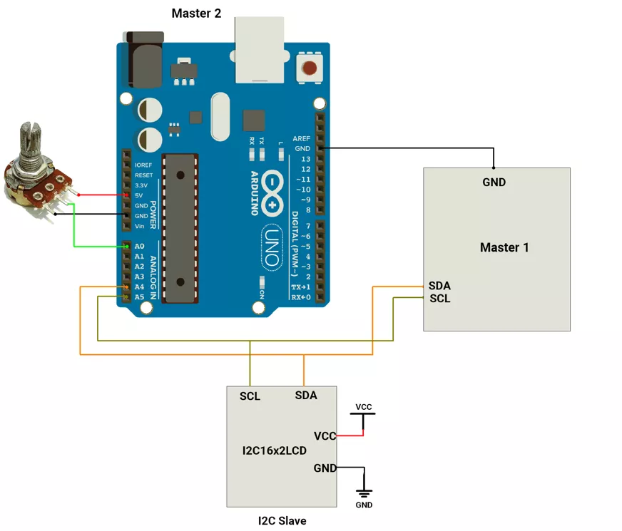
Hardware Connection
- Connect the LCD’s I²C module to Master 2 using:
- SDA → A4
- SCL → A5
- Connect Master 1’s SDA and SCL lines in parallel with Master 2’s SDA and SCL lines and the LCD.
This creates a shared I²C bus, allowing both masters to communicate with the same LCD using only two wires (SDA and SCL) along with common VCC and GND.
Circuit Diagram
Code
#include <Wire.h>
#include <Arduino.h>

/*User Configuration*/
#define LCD_I2C_ADDRESS 0x27  // I2C address of LCD (check using I2C scanner)
#define ADC_PIN A0            // Analog pin connected to potentiometer

#define LCD_DELAY_MS(ms) delay(ms)              // Millisecond delay
#define LCD_DELAY_US(us) delayMicroseconds(us)  // Microsecond delay

/*LCD Bit Mapping
   PCF8574 I2C Expander Pin Mapping:
   P0 = RS, P1 = RW, P2 = EN, P3 = Backlight, P4–P7 = D4–D7 (4-bit data)
*/
#define LCD_EN 0x04U         // Enable signal bit
#define LCD_RW 0x02U         // Read/Write control (0 = Write)
#define LCD_RS 0x01U         // Register Select (0 = Command, 1 = Data)
#define LCD_BACKLIGHT 0x08U  // Backlight ON bit

static uint8_t s_backlight = LCD_BACKLIGHT;  // Keeps LCD backlight always ON

// Splits 8-bit data into two 4-bit nibbles and generates the sequence
// required to latch them into the LCD using EN HIGH→LOW pulses.
static int build_nibble_seq(uint8_t data, uint8_t control, uint8_t *out) {
  out[0] = s_backlight | control | (data & 0xF0) | LCD_EN;         // Send upper nibble with EN=1
  out[1] = s_backlight | control | (data & 0xF0);                  // EN=0
  out[2] = s_backlight | control | ((data << 4) & 0xF0) | LCD_EN;  // Send lower nibble with EN=1
  out[3] = s_backlight | control | ((data << 4) & 0xF0);           // EN=0
  return 4;                                                        // Returns total 4 bytes created
}


//Sends an LCD command (RS=0).
static void lcd_command(uint8_t cmd) {
  uint8_t seq[4];
  build_nibble_seq(cmd, 0, seq);  // RS=0 for command
  Wire.beginTransmission(LCD_I2C_ADDRESS);
  Wire.write(seq, 4);      // Send data bytes
  Wire.endTransmission();  // End I2C transmission
}

//Sends a character (RS=1) to LCD.
static void lcd_data(uint8_t data) {
  uint8_t seq[4];
  build_nibble_seq(data, LCD_RS, seq);  // RS=1 for data
  Wire.beginTransmission(LCD_I2C_ADDRESS);
  Wire.write(seq, 4);
  Wire.endTransmission();
  LCD_DELAY_US(50);  // Short delay after data
}

/* LCD Initialization */
void lcd_init() {
  Wire.begin();  // Start I2C communication

  // Turn on LCD backlight
  Wire.beginTransmission(LCD_I2C_ADDRESS);
  Wire.write(s_backlight);
  Wire.endTransmission();

  LCD_DELAY_MS(50);  // Wait for LCD power-up

  // Initialization sequence (switch to 4-bit mode)
  lcd_command(0x30);
  LCD_DELAY_MS(5);
  lcd_command(0x30);
  LCD_DELAY_US(150);
  lcd_command(0x30);
  LCD_DELAY_US(150);
  lcd_command(0x20);
  LCD_DELAY_MS(5);  // Set 4-bit mode

  // Function set: 4-bit, 2-line, 5x8 dots
  lcd_command(0x28);
  LCD_DELAY_US(50);

  // Display OFF
  lcd_command(0x08);
  LCD_DELAY_US(50);

  // Clear display
  lcd_command(0x01);
  LCD_DELAY_MS(3);

  // Entry mode: increment cursor automatically
  lcd_command(0x06);
  LCD_DELAY_US(50);

  // Display ON, cursor OFF
  lcd_command(0x0C);
  LCD_DELAY_US(50);
}

/*LCD Write Function
   Writes a string at the specified row and column on the LCD.
*/
void lcd_write(uint8_t row, uint8_t col, const char *str) {
  if (!str) return;  // Skip if string is empty

  // Calculate DDRAM address for given row and column
  uint8_t addr;
  switch (row) {
    case 0: addr = 0x80 + col; break;  // Line 1
    case 1: addr = 0xC0 + col; break;  // Line 2
    case 2: addr = 0x94 + col; break;  // Line 3 (for 20x4 LCDs)
    case 3: addr = 0xD4 + col; break;  // Line 4 (for 20x4 LCDs)
    default: addr = 0x80 + col; break;
  }

  uint8_t seq[4];

  /* Send Cursor Position Command */
  Wire.beginTransmission(LCD_I2C_ADDRESS);
  build_nibble_seq(addr, 0x00U, seq);  // RS=0 for command
  Wire.write(seq, 4);
  Wire.endTransmission(false);  // No STOP (keep I2C active)

  /*Send Characters to LCD */
  size_t len = strlen(str);
  for (size_t i = 0; i < len; i++) {
    build_nibble_seq((uint8_t)str[i], LCD_RS, seq);  // RS=1 for data
    Wire.beginTransmission(LCD_I2C_ADDRESS);
    Wire.write(seq, 4);
    if (i < len - 1)
      Wire.endTransmission(false);  // Keep I2C active
    else
      Wire.endTransmission(true);  // Last char → send STOP
  }

  LCD_DELAY_MS(2);  // Short wait for LCD
}

/*Utility Functions*/
void lcd_clear() {
  lcd_command(0x01);  // Clear display
  LCD_DELAY_MS(3);
}

/*Setup*/
void setup() {
  delay(1000);  // Allow power stabilization
  Serial.begin(115200);
  Serial.println("Initializing LCD...");
  lcd_init();   // Initialize LCD
  lcd_clear();  // Clear any junk data
}


void loop() {
  static unsigned long lastUpdate = 0;

  // Update every 1 second
  if (millis() - lastUpdate > 1000) {
    lastUpdate = millis();

    uint16_t adcValue = analogRead(ADC_PIN);  // Read analog input (0–1023)

    char buff[20];
    sprintf(buff, "POT Value: %04d ", adcValue);  // Format display text

    lcd_write(1, 0, buff);  // Print on LCD line 2
  }
}
Code Explanation
Wire.begin()- Initializes the Arduino as an I²C master.
- This enables communication with the LCD module (PCF8574) using only two wires (SDA → A4, SCL → A5).
- LCD Initialization Sequence:
The LCD does not automatically start in 4-bit mode, so initialization commands are sent to set it up properly:lcd_command(0x30)(sent three times) ensures the LCD is awake and in 8-bit mode.lcd_command(0x20)switches it to 4-bit communication mode, reducing the number of data pins needed.- This sequence follows the HD44780 LCD datasheet recommendation for reliable startup.
- Function Configuration:
After switching to 4-bit mode, the following commands configure LCD behavior:- 0x28 → Function Set: 4-bit mode, 2 display lines, 5×8 font.
- 0x08 → Display OFF (used temporarily during setup).
- 0x01 → Clear Display (removes old data).
- 0x06 → Entry Mode Set: auto-increment cursor after each character.
- 0x0C → Display ON, cursor OFF (final ready state).
- Data Transmission
- The
build_nibble_seq()function splits each 8-bit command or character into two 4-bit nibbles (upper and lower). - Each nibble is latched using an EN (Enable) pulse — HIGH → LOW transition.
- The RS (Register Select) bit decides what type of data is being sent:
- RS = 0 → Command
- RS = 1 → Display Character
- The
Wire.write()andWire.endTransmission()functions handle I²C communication between Arduino and the LCD module.
- The
- Cursor Positioning:
Before printing text, the code calculates the LCD DDRAM address to move the cursor to a specific row and column:- Line 1 → 0x80 + column
- Line 2 → 0xC0 + column
These base addresses are defined by the LCD’s internal memory map.
- ADC Reading:
analogRead(ADC_PIN)reads the voltage from a potentiometer connected to analog pin A0.- The ADC converts the analog voltage (0–5V) to a digital value (0–1023).
- This value is formatted into a string using:
sprintf(buff, "POT Value: %04d ", adcValue);
which ensures a clean display format like "POT Value: 0450".
- Display Update Logic
- The code updates the display every 1 second using:
if (millis() - lastUpdate > 1000) - After each interval, it reads the latest ADC value and displays it on line 2 of the LCD using:
lcd_write(1, 0, buff); lcd_write()
Handles both cursor movement and character transmission:- Moves the cursor to the correct address (row, column).
- Sends characters one by one to the LCD.
- Due to I²C buffer limits, each character is sent in a separate write, but
Wire.endTransmission(false)keeps the bus active—allowing the whole string to be sent in one continuous I²C transaction without losing bus control.
lcd_clear()
Clears the LCD display (0x01 command) and resets the cursor to the home position.
- The code updates the display every 1 second using:
- setup()
- Waits for power stabilization (1 second).
- Starts serial communication for debugging.
- Initializes the LCD with
lcd_init()and clears the display.
- loop()
- Reads the potentiometer ADC value every 1 second.
- Formats the value into a readable string.
- Displays it on the second line of the LCD.
OUTPUT
Hardware Setup