59. Multi-Slave I2C Communication
We need to interface three I²C slave devices with a master microcontroller:
- BMP180 Sensor – Measures pressure, temperature, and altitude (operates at 3.3 V).
- DS1307 RTC – Provides real-time clock and calendar functions (operates at 5V).
- OLED Display – Displays acquired data (operates at 3.3 V to 5 V).
The I²C communication frequency is set to 100 kHz, which is supported by all slave devices.
Voltage Level Compatibility
Before establishing connections, ensure that all devices operate within their safe voltage levels to prevent potential damage.
The diagram below (referenced from the datasheet) illustrates how a voltage level translator can be used to connect devices operating at different voltage domains.
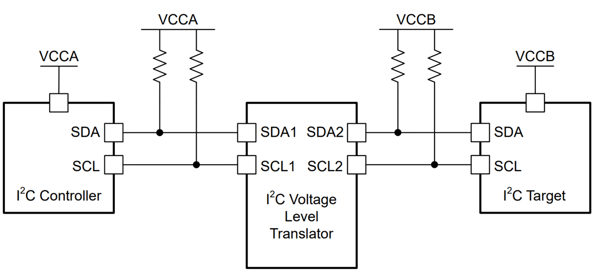
- BMP180 includes an inbuilt voltage regulator (662k), allowing its SDA and SCL lines to be connected directly to the microcontroller without an external level shifter.
- Supply the BMP180 module with 3.3 V to ensure correct operation.
- So, when interfacing I²C devices operating at different voltages (e.g., 5 V ↔ 3.3 V), always use a voltage level shifter to ensure safe logic levels and reliable communication.
Interfacing I²C Buses Across Voltage Domains
When mixing I²C devices and microcontrollers operating at different logic voltages, two common scenarios arise. Careful bus-level management is necessary because I²C relies on open-drain lines pulled up to a defined voltage level.
1) Interfacing 5 V I²C Peripherals with a 3.3 V-Only Microcontroller
Challenge
- The microcontroller’s I/O pins are not 5V-tolerant.
- If pulled up to 5 V, the MCU inputs could be damaged.
Solutions
- Pull-Ups to 3.3 V Only
- Connect SDA and SCL pull-ups to 3.3 V.
- 3.3 V idle high level is safe for the MCU and usually recognized by 5 V peripherals as a valid logic “1.”
- No extra hardware needed if the 5 V devices are 3.3 V-tolerant on their I/O pins.
- Bidirectional Level Shifter
- Use a MOSFET-based or integrated I²C level translator (e.g., using BSS138).
- MCU side pull-up to 3.3 V, peripheral side pull-up to 5 V.
- Ensures safe voltage domains while maintaining open-drain operation.
2) Interfacing 3.3 V I²C Peripherals with a 5 V-Only Microcontroller
Challenge
- The 5 V MCU’s SDA/SCL lines are pulled up to 5 V, which may overstress the 3.3 V device’s pins.
Solutions
- Pull-Ups to 3.3 V Only + Verify Logic Recognition
- Tie pull-ups to 3.3 V.
- Ensure the 5 V MCU recognizes 3.3 V as logic “1” (check MCU datasheet for V_IH ≤ 3.3 V).
- No extra hardware needed if this condition is met.
- Bidirectional Level Shifter
- Insert a level shifter between the MCU and the peripheral.
- High-side pull-ups to 5 V, low-side to 3.3 V.
- Prevents voltage overstress and ensures reliable communication.
Best Practices for Mixed-Voltage I²C Systems
- Use Open-Drain Configuration – All devices should only pull the lines low, never drive them high.
- Select Proper Pull-Up Resistors – Typical values are 4.7 kΩ to 10 kΩ. Place them near the master or mid-bus.
- Verify Voltage Tolerances – Check device datasheets for V_IH, V_IL, and V_MAX on SDA/SCL pins.
- Use a Logic Analyzer – Verify idle high voltage, clean rising edges, and correct ACK/NACK responses at the chosen bus speed.
By selecting the correct pull-up voltage or integrating a bidirectional level translator when required, 3.3 V and 5 V I²C devices can safely coexist on the same bus without communication issues or damage.
Hardware Connections
Step-by-step:
- Connect 3.3 V and GND from the master MCU to the BMP180 sensor module, the OLED display and DS1307 RTC module.
- Connect the SDA and SCL lines of all devices.
- Use appropriate pull-up resistors on SDA and SCL lines (as per voltage domain).
- Ensure all devices share a common ground.
- Confirm total current draw is within the MCU’s sourcing/sinking limits to prevent overloading.
Final Implementation
Once the master and slave devices are connected and the I²C bus is configured, the task can be implemented using various platforms:
- STM32
- ESP32
- Arduino UNO
We’re using an STM32 NUCLEO-F103RB board as a master, which operates at a 3.3V logic level.
Key Peripherals Used:
- I2C1 – Facilitates I2C communication between the Master and Slave.
- USART2 – Provides serial communication with a terminal for displaying debug messages.
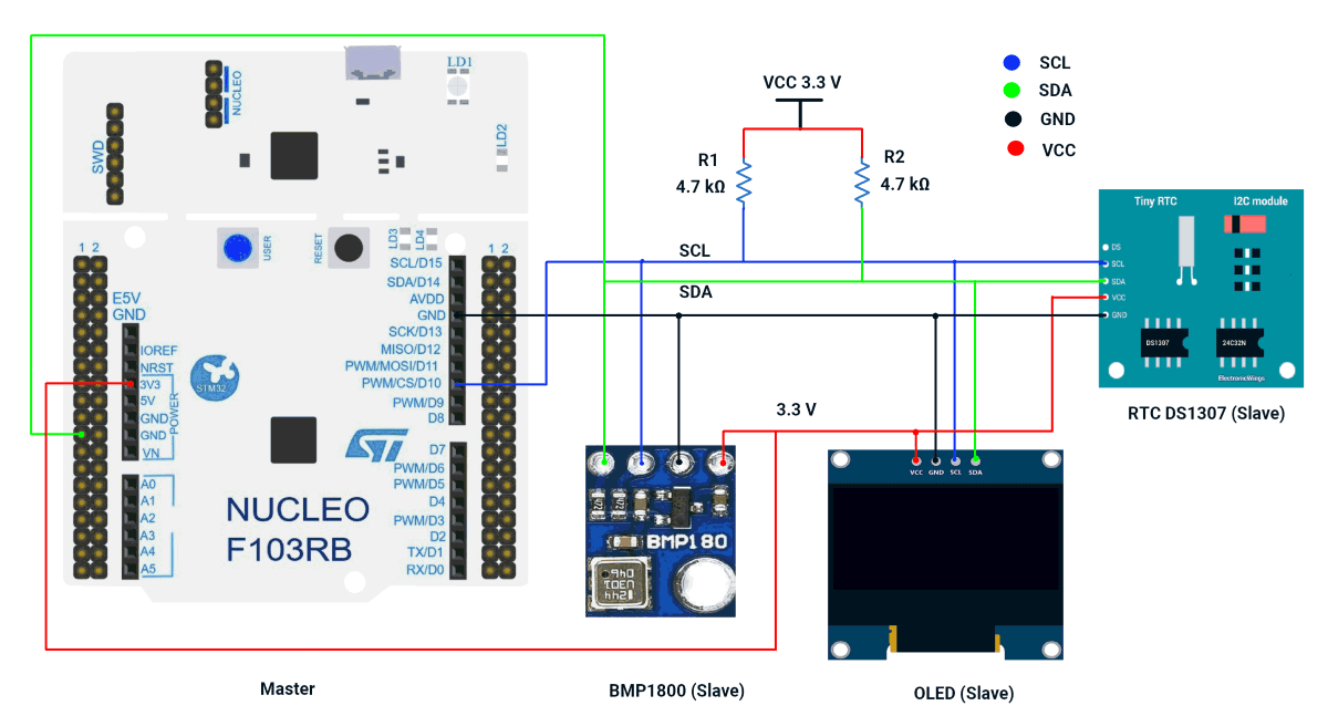
STM32 Hardware Connection
- Connect PB6 → SCL pins of the Slaves.
- Connect PB7 → SDA pins of the Slaves.
- Connect 3.3 V to the BMP180 sensor module, the OLED display and DS1307 RTC module.
- Ensure a shared GND between the Master and Slaves.
- Place 4.7 kΩ pull-up resistors between VCC 3.3 V and each of the SDA and SCL lines.
- Connect the USB cable to the PC for power and UART communication.
Note: RTC DS1307 Breakout Power & Logic Levels
In our DS1307 breakout board, the onboard pull-up resistors connect SDA/SCL to VCC.
- When RTC is powered at 5 V, the I²C lines are pulled up to 5 V, which can damage 3.3 V controllers (ESP32/STM32).
- For demonstration, we powered the module at 3.3 V, which keeps logic levels safe but is not recommended for long-term use, since the DS1307 is specified for 4.5–5.5 V and may lose accuracy below this range.
Recommended practice: Power the DS1307 at 5 V and use an I²C level shifter for safe, reliable operation.
Circuit Diagram
STM32 Firmware Implementation
Project Setup in STM32CubeIDE
- Create a Project
- Open STM32CubeIDE, start a new project, and select the NUCLEO-F103RB board.
- Basic Configuration (via CubeMX inside CubeIDE)
- Clock: Use the default HSI oscillator with PLL enabled (as configured in SystemClock_Config).
- GPIO: Enable clocks for PORTA, PORTB, PORTC, and PORTD.
- I2C1: I2C mode (Standard mode, 100kHz clock).
- USART2: Enabled at 115200 baud, 8-N-1, for debugging/expansion if needed.
- Code Generation
- CubeMX will automatically generate all the startup code, including:
HAL_Init()→ Initializes HAL and system tick.SystemClock_Config()→ Configures system clock (HSI + PLL).MX_GPIO_Init()→ Initializes GPIO ports.MX_USART2_UART_Init()→ Configures UART2.MX_I2C1_Init()→ Configures I2C1.
- This code sets up the hardware and prepares the project for firmware development, so we only need to add our application logic in the user code sections
- CubeMX will automatically generate all the startup code, including:
Code Snippets from main.c
I2C Initialization (MX_I2C1_Init)
hi2c1.Instance = I2C1;
hi2c1.Init.ClockSpeed = 100000;       // 100kHz
hi2c1.Init.DutyCycle = I2C_DUTYCYCLE_2;
hi2c1.Init.AddressingMode = I2C_ADDRESSINGMODE_7BIT;
if (HAL_I2C_Init(&hi2c1) != HAL_OK) {
  Error_Handler();
}- Initializes I2C1 peripheral with 100kHz clock speed, standard duty cycle, and 7-bit addressing mode.
Header includes
#include <stdio.h>
#include <string.h>
#include <math.h>
#include <stdlib.h>- Includes standard C libraries (stdio.h, string.h, math.h, stdlib.h) for various functions.
Private typedefs, defines, and Global variables
typedef struct {
   uint8_t sec, min, hour, date, month;
   uint16_t year;
} RTC_Time;

#define DS1307_ADDR   (0x68 << 1)

#define BMP180_ADDR   (0x77 << 1)

/* SSD1306 Command definitions */
#define OLED_ADDR     (0x3C << 1)
#define OLED_CMD_MODE     0x00
#define OLED_DATA_MODE    0x40

uint8_t oled_buffer[1024];- Defines an RTC_Time struct to store date/time components.
- Defines I2C addresses for DS1307 (RTC), BMP180 (pressure sensor), and SSD1306 (OLED).
- Declares an oled_buffer for display data.
OLED Driver
// ========== OLED DRIVER ==========
/* Font 5x7 for ASCII 32-126 */
const uint8_t Font5x7[][5] = {
 // ASCII 32–126 (Printable characters)
 {0x00,0x00,0x00,0x00,0x00}, // space
 {0x00,0x00,0x5F,0x00,0x00}, // !
 {0x00,0x07,0x00,0x07,0x00}, // "
 {0x14,0x7F,0x14,0x7F,0x14}, // #
 {0x24,0x2A,0x7F,0x2A,0x12}, // $
 {0x23,0x13,0x08,0x64,0x62}, // %
 {0x36,0x49,0x55,0x22,0x50}, // &
 {0x00,0x05,0x03,0x00,0x00}, // '
 {0x00,0x1C,0x22,0x41,0x00}, // (
 {0x00,0x41,0x22,0x1C,0x00}, // )
 {0x14,0x08,0x3E,0x08,0x14}, // *
 {0x08,0x08,0x3E,0x08,0x08}, // +
 {0x00,0x50,0x30,0x00,0x00}, // ,
 {0x08,0x08,0x08,0x08,0x08}, // -
 {0x00,0x60,0x60,0x00,0x00}, // .
 {0x20,0x10,0x08,0x04,0x02}, // /
 {0x3E,0x51,0x49,0x45,0x3E}, // 0
 {0x00,0x42,0x7F,0x40,0x00}, // 1
 {0x42,0x61,0x51,0x49,0x46}, // 2
 {0x21,0x41,0x45,0x4B,0x31}, // 3
 {0x18,0x14,0x12,0x7F,0x10}, // 4
 {0x27,0x45,0x45,0x45,0x39}, // 5
 {0x3C,0x4A,0x49,0x49,0x30}, // 6
 {0x01,0x71,0x09,0x05,0x03}, // 7
 {0x36,0x49,0x49,0x49,0x36}, // 8
 {0x06,0x49,0x49,0x29,0x1E}, // 9
 {0x00,0x36,0x36,0x00,0x00}, // :
 {0x00,0x56,0x36,0x00,0x00}, // ;
 {0x08,0x14,0x22,0x41,0x00}, // <
 {0x14,0x14,0x14,0x14,0x14}, // =
 {0x00,0x41,0x22,0x14,0x08}, // >
 {0x02,0x01,0x51,0x09,0x06}, // ?
 {0x32,0x49,0x79,0x41,0x3E}, // @
 {0x7E,0x11,0x11,0x11,0x7E}, // A
 {0x7F,0x49,0x49,0x49,0x36}, // B
 {0x3E,0x41,0x41,0x41,0x22}, // C
 {0x7F,0x41,0x41,0x22,0x1C}, // D
 {0x7F,0x49,0x49,0x49,0x41}, // E
 {0x7F,0x09,0x09,0x09,0x01}, // F
 {0x3E,0x41,0x49,0x49,0x7A}, // G
 {0x7F,0x08,0x08,0x08,0x7F}, // H
 {0x00,0x41,0x7F,0x41,0x00}, // I
 {0x20,0x40,0x41,0x3F,0x01}, // J
 {0x7F,0x08,0x14,0x22,0x41}, // K
 {0x7F,0x40,0x40,0x40,0x40}, // L
 {0x7F,0x02,0x0C,0x02,0x7F}, // M
 {0x7F,0x04,0x08,0x10,0x7F}, // N
 {0x3E,0x41,0x41,0x41,0x3E}, // O
 {0x7F,0x09,0x09,0x09,0x06}, // P
 {0x3E,0x41,0x51,0x21,0x5E}, // Q
 {0x7F,0x09,0x19,0x29,0x46}, // R
 {0x46,0x49,0x49,0x49,0x31}, // S
 {0x01,0x01,0x7F,0x01,0x01}, // T
 {0x3F,0x40,0x40,0x40,0x3F}, // U
 {0x1F,0x20,0x40,0x20,0x1F}, // V
 {0x3F,0x40,0x38,0x40,0x3F}, // W
 {0x63,0x14,0x08,0x14,0x63}, // X
 {0x07,0x08,0x70,0x08,0x07}, // Y
 {0x61,0x51,0x49,0x45,0x43}, // Z
 {0x7F,0x41,0x41,0x41,0x41}, // [
 {0x02,0x04,0x08,0x10,0x20}, // backslash
 {0x41,0x41,0x41,0x41,0x7F}, // ]
 {0x04,0x02,0x01,0x02,0x04}, // ^
 {0x40,0x40,0x40,0x40,0x40}, // _
 {0x00,0x01,0x02,0x04,0x00}, // `
 {0x20,0x54,0x54,0x54,0x78}, // a
 {0x7F,0x48,0x44,0x44,0x38}, // b
 {0x38,0x44,0x44,0x44,0x20}, // c
 {0x38,0x44,0x44,0x48,0x7F}, // d
 {0x38,0x54,0x54,0x54,0x18}, // e
 {0x08,0x7E,0x09,0x01,0x02}, // f
 {0x0C,0x52,0x52,0x52,0x3E}, // g
 {0x7F,0x08,0x04,0x04,0x78}, // h
 {0x00,0x44,0x7D,0x40,0x00}, // i
 {0x20,0x40,0x44,0x3D,0x00}, // j
 {0x7F,0x10,0x28,0x44,0x00}, // k
 {0x00,0x41,0x7F,0x40,0x00}, // l
 {0x7C,0x04,0x18,0x04,0x78}, // m
 {0x7C,0x08,0x04,0x04,0x78}, // n
 {0x38,0x44,0x44,0x44,0x38}, // o
 {0x7C,0x14,0x14,0x14,0x08}, // p
 {0x08,0x14,0x14,0x18,0x7C}, // q
 {0x7C,0x08,0x04,0x04,0x08}, // r
 {0x48,0x54,0x54,0x54,0x20}, // s
 {0x04,0x3F,0x44,0x40,0x20}, // t
 {0x3C,0x40,0x40,0x20,0x7C}, // u
 {0x1C,0x20,0x40,0x20,0x1C}, // v
 {0x3C,0x40,0x30,0x40,0x3C}, // w
 {0x44,0x28,0x10,0x28,0x44}, // x
 {0x0C,0x50,0x50,0x50,0x3C}, // y
 {0x44,0x64,0x54,0x4C,0x44}  // z
};


void OLED_SendCommand(uint8_t command) {
   uint8_t data[2] = {OLED_CMD_MODE, command};
   HAL_I2C_Master_Transmit(&hi2c1, OLED_ADDR, data, 2, HAL_MAX_DELAY);
}


void OLED_SendData(uint8_t *data, uint16_t size) {
   uint8_t buffer[size + 1];
   buffer[0] = OLED_DATA_MODE;
   memcpy(&buffer[1], data, size);
   HAL_I2C_Master_Transmit(&hi2c1, OLED_ADDR, buffer, size + 1, HAL_MAX_DELAY);
}


void OLED_Init(void) {
   HAL_Delay(100);
   OLED_SendCommand(0xAE);
   OLED_SendCommand(0xA6);
   OLED_SendCommand(0x20);
   OLED_SendCommand(0x00);
   OLED_SendCommand(0xB0);
   OLED_SendCommand(0xC8);
   OLED_SendCommand(0x00);
   OLED_SendCommand(0x10);
   OLED_SendCommand(0x40);
   OLED_SendCommand(0x81);
   OLED_SendCommand(0x7F);
   OLED_SendCommand(0xA1);
   OLED_SendCommand(0xA6);
   OLED_SendCommand(0xA8);
   OLED_SendCommand(0x3F);
   OLED_SendCommand(0xA4);
   OLED_SendCommand(0xD3);
   OLED_SendCommand(0x00);
   OLED_SendCommand(0xD5);
   OLED_SendCommand(0xF0);
   OLED_SendCommand(0xD9);
   OLED_SendCommand(0x22);
   OLED_SendCommand(0xDA);
   OLED_SendCommand(0x12);
   OLED_SendCommand(0xDB);
   OLED_SendCommand(0x20);
   OLED_SendCommand(0x8D);
   OLED_SendCommand(0x14);
   OLED_SendCommand(0xAF);
}


void OLED_SetCursor(uint8_t x, uint8_t y) {
   OLED_SendCommand(0xB0 + y);
   OLED_SendCommand(0x00 + (x & 0x0F));
   OLED_SendCommand(0x10 + ((x >> 4) & 0x0F));
}


void OLED_DrawText(uint8_t x, uint8_t y, const char *text) {
   while (*text) {
       char c = *text;
       if (c < 32 || c > 126) c = '?';
       OLED_SetCursor(x, y);
       uint8_t buffer[6];
       memcpy(buffer, Font5x7[c - 32], 5);  // copy 5 font bytes
       buffer[5] = 0x00;  // add 1 column space
       OLED_SendData(buffer, 6);  // send all 6 bytes at once with one 0x40 header
       x += 6;
       if (x + 6 >= 128) break;
       text++;
   }
}


void OLED_Clear(void) {
   for (uint8_t page = 0; page < 8; page++) {
       OLED_SetCursor(0, page);  // set column to 0, row to `page`
       uint8_t empty[128];
       memset(empty, 0x00, 128); // fill array with zeros
       OLED_SendData(empty, 128); // clear the whole page (128 columns)
   }
}
- Font Data: 5x7 font for ASCII characters 32-126.
- Functions:
- OLED_SendCommand: Sends commands to the OLED.
- OLED_SendData: Sends data to the OLED.
- OLED_Init: Initializes the OLED display.
- OLED_SetCursor: Sets the cursor position.
- OLED_DrawText: Displays text using the 5x7 font.
- OLED_Clear: Clears the display.
BMP180 DRIVER
// ========== BMP180 DRIVER ==========
int32_t bmp_UT, bmp_UP;
int16_t ac1, ac2, ac3, b1, b2, mb, mc, md;
uint16_t ac4, ac5, ac6;
void BMP180_ReadCalibration(void) {
   uint8_t data[22];
   HAL_I2C_Mem_Read(&hi2c1, BMP180_ADDR, 0xAA, 1, data, 22, HAL_MAX_DELAY);
   ac1 = (data[0]<<8)|data[1];
   ac2 = (data[2]<<8)|data[3];
   ac3 = (data[4]<<8)|data[5];
   ac4 = (data[6]<<8)|data[7];
   ac5 = (data[8]<<8)|data[9];
   ac6 = (data[10]<<8)|data[11];
   b1  = (data[12]<<8)|data[13];
   b2  = (data[14]<<8)|data[15];
   mb  = (data[16]<<8)|data[17];
   mc  = (data[18]<<8)|data[19];
   md  = (data[20]<<8)|data[21];
}


int32_t BMP180_ReadTemperature(void) {
   uint8_t cmd = 0x2E;
   HAL_I2C_Mem_Write(&hi2c1, BMP180_ADDR, 0xF4, 1, &cmd, 1, HAL_MAX_DELAY);
   HAL_Delay(5);
   uint8_t data[2];
   HAL_I2C_Mem_Read(&hi2c1, BMP180_ADDR, 0xF6, 1, data, 2, HAL_MAX_DELAY);
   bmp_UT = (data[0] << 8) | data[1];
   int32_t X1 = ((bmp_UT - (int32_t)ac6) * (int32_t)ac5) >> 15;
   int32_t X2 = ((int32_t)mc << 11) / (X1 + md);
   int32_t B5 = X1 + X2;
   return (B5 + 8) >> 4;
}


int32_t BMP180_ReadPressure(void) {
   uint8_t cmd = 0x34;
   HAL_I2C_Mem_Write(&hi2c1, BMP180_ADDR, 0xF4, 1, &cmd, 1, HAL_MAX_DELAY);
   HAL_Delay(8);
   uint8_t data[3];
   HAL_I2C_Mem_Read(&hi2c1, BMP180_ADDR, 0xF6, 1, data, 3, HAL_MAX_DELAY);
   bmp_UP = ((data[0]<<16)|(data[1]<<8)|data[2]) >> 8;
   int32_t X1 = ((bmp_UT - (int32_t)ac6) * (int32_t)ac5) >> 15;
   int32_t X2 = ((int32_t)mc << 11) / (X1 + md);
   int32_t B5 = X1 + X2;
   int32_t B6 = B5 - 4000;
   X1 = (b2 * ((B6 * B6) >> 12)) >> 11;
   X2 = (ac2 * B6) >> 11;
   int32_t X3 = X1 + X2;
   int32_t B3 = (((((int32_t)ac1) * 4 + X3) << 0) + 2) >> 2;
   X1 = (ac3 * B6) >> 13;
   X2 = (b1 * ((B6 * B6) >> 12)) >> 16;
   X3 = ((X1 + X2) + 2) >> 2;
   uint32_t B4 = (ac4 * (uint32_t)(X3 + 32768)) >> 15;
   uint32_t B7 = ((uint32_t)bmp_UP - B3) * 50000;
   int32_t p = (B7 < 0x80000000) ? (B7 * 2 / B4) : (B7 / B4 * 2);
   X1 = (p >> 8) * (p >> 8);
   X1 = (X1 * 3038) >> 16;
   X2 = (-7357 * p) >> 16;
   return p + ((X1 + X2 + 3791) >> 4);
}


float BMP180_ReadAltitude(float pressure) {
   return 44330.0 * (1.0 - pow((pressure / 101325.0), 0.1903));
}- Calibration: Reads calibration data from the BMP180 sensor.
- Functions:
- BMP180_ReadTemperature: Reads and calculates temperature.
- BMP180_ReadPressure: Reads and calculates pressure.
- BMP180_ReadAltitude: Calculates altitude from pressure.
RTC DS1307 DRIVER
// ========== RTC DS1307 DRIVER ==========
#define DS1307_SECONDS_REG 0x00

// Helper: Convert BCD to Decimal
uint8_t bcd2dec(uint8_t val) {
  return ((val >> 4) * 10 + (val & 0x0F));
}

// Helper: Convert Decimal to BCD
uint8_t decToBcd(uint8_t val) {
   return ((val / 10 * 16) + (val % 10));
}


// Month name to number conversion
uint8_t monthStrToNumber(const char* month) {
   if (strcmp(month, "Jan") == 0) return 1;
   if (strcmp(month, "Feb") == 0) return 2;
   if (strcmp(month, "Mar") == 0) return 3;
   if (strcmp(month, "Apr") == 0) return 4;
   if (strcmp(month, "May") == 0) return 5;
   if (strcmp(month, "Jun") == 0) return 6;
   if (strcmp(month, "Jul") == 0) return 7;
   if (strcmp(month, "Aug") == 0) return 8;
   if (strcmp(month, "Sep") == 0) return 9;
   if (strcmp(month, "Oct") == 0) return 10;
   if (strcmp(month, "Nov") == 0) return 11;
   if (strcmp(month, "Dec") == 0) return 12;
   return 0;
}


void DS1307_SetTimeFromCompile(void) {
   // __DATE__ format: "Jul 18 2025"
   // __TIME__ format: "14:33:22"
   char monthStr[4];
   int day, year, hour, minute, second;
   sscanf(__DATE__, "%3s %d %d", monthStr, &day, &year);
   sscanf(__TIME__, "%d:%d:%d", &hour, &minute, &second);
   uint8_t month = monthStrToNumber(monthStr);
   uint8_t rtc_data[7];
   rtc_data[0] = decToBcd((uint8_t)second);     // Seconds
   rtc_data[1] = decToBcd((uint8_t)minute);     // Minutes
   rtc_data[2] = decToBcd((uint8_t)hour);       // Hours (24h mode)
   rtc_data[3] = 1;                              // Day of week (1 = Monday)
   rtc_data[4] = decToBcd((uint8_t)day);        // Day
   rtc_data[5] = decToBcd((uint8_t)month);      // Month
   rtc_data[6] = decToBcd((uint8_t)(year % 100)); // Year (00-99)
   HAL_I2C_Mem_Write(&hi2c1, DS1307_ADDR, DS1307_SECONDS_REG,
                     I2C_MEMADD_SIZE_8BIT, rtc_data, 7, HAL_MAX_DELAY);
}


void DS1307_GetTime(RTC_Time* t) {
   uint8_t data[7];
   HAL_I2C_Mem_Read(&hi2c1, DS1307_ADDR, 0x00, 1, data, 7, HAL_MAX_DELAY);
   t->sec   = bcd2dec(data[0]);
   t->min   = bcd2dec(data[1]);
   t->hour  = bcd2dec(data[2]);
   t->date  = bcd2dec(data[4]);
   t->month = bcd2dec(data[5]);
   t->year  = bcd2dec(data[6]) + 2000;
}- Helpers:
- bcd2dec and decToBcd: Convert between BCD and decimal.
- monthStrToNumber: Converts month names to numbers.
- Functions:
- DS1307_SetTimeFromCompile: Sets RTC time from compile-time.
- DS1307_GetTime: Reads current time from RTC.
Main Loop Logic
OLED_Init();
BMP180_ReadCalibration();
DS1307_SetTimeFromCompile();

OLED_Clear();

while (1) {
  RTC_Time now;
  DS1307_GetTime(&now);
  int32_t temp = BMP180_ReadTemperature();  // Temperature in tenths of a degree
  int32_t press = BMP180_ReadPressure();    // Pressure in Pascals
  float alt = BMP180_ReadAltitude(press);   // Altitude in meters

  char line[32];  // Buffer for display strings

  // Format date: DD/MM/YYYY
  snprintf(line, sizeof(line), "%02u/%02u/%04u", now.date, now.month, now.year);
  OLED_DrawText(0, 0, line);

  // Format time: HH:MM:SS
  snprintf(line, sizeof(line), "%02u:%02u:%02u", now.hour, now.min, now.sec);
  OLED_DrawText(70, 0, line);

  // Format pressure: Pressure: xxxxx Pa
  snprintf(line, sizeof(line), "Pressure: %ld Pa", (long)press);
  OLED_DrawText(0, 2, line);

  // Format temperature: Temp: xx.x C
  snprintf(line, sizeof(line), "Temp: %ld.%01lu C", (long)(temp / 10), (unsigned long)labs(temp % 10));
  OLED_DrawText(0, 4, line);

  // Format altitude: Altitude: xxx.xx m
  int32_t alt_int = (int32_t)alt;
  uint32_t alt_frac = (uint32_t)((alt - alt_int) * 100.0f + 0.5f);  // Rounded
  snprintf(line, sizeof(line), "Altitude: %ld.%02lu m", (long)alt_int, (unsigned long)alt_frac);
  OLED_DrawText(0, 6, line);

  HAL_Delay(1000);
}- Initializes OLED, BMP180, and RTC.
- Continuously reads and displays:
- Date and time (from RTC).
- Temperature, pressure, and altitude (from BMP180).
- Updates the OLED display every second.
Expected OLED Display Output
When the STM32 NUCLEO-F103RB master runs the firmware, the OLED will refresh every second with the following five lines of text:
Example :
DD/MM/YYYY          HH:MM:SS
Pressure: 101325 Pa
Temp: 24.3 C
Altitude: 15.23 m- Row 1 shows the compile-time date/time from the DS1307 RTC (set by DS1307_SetTimeFromCompile()).
- Rows 2, 3, and 4 display live measurements from the BMP180: pressure, temperature, and calculated altitude.
- The display updates once per second in the main loop.
Download Project
The complete STM32CubeIDE project (including .ioc configuration, main.c, and HAL files) is available here:
📥 Download Project
We are using the ESP32 DevKit v4 development board and programming it using the Arduino IDE.
- Before uploading, make sure to select “ESP32 Dev Module” as the board to ensure correct settings and compatibility.
In both ESP32 master and slave codes, the Wire.h library is used for I²C communication.
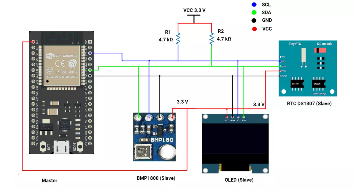
ESP32 Circuit Connection
- Connect 22 ➔ SCL of all slaves.
- Connect 21 ➔ SDA of all slaves.
- Common GND of ESP32 ➔ RTC GND.
- Place 4.7 kΩ pull-up resistors between VCC(3.3V) and each of the SDA and SCL lines.
Note: RTC DS1307 Breakout Power & Logic Levels
In our DS1307 breakout board, the onboard pull-up resistors connect SDA/SCL to VCC.
- When RTC is powered at 5 V, the I²C lines are pulled up to 5 V, which can damage 3.3 V controllers (ESP32/STM32).
- For demonstration, we powered the module at 3.3 V, which keeps logic levels safe but is not recommended for long-term use, since the DS1307 is specified for 4.5–5.5 V and may lose accuracy below this range.
Recommended practice: Power the DS1307 at 5 V and use an I²C level shifter for safe, reliable operation.
Circuit Diagram
ESP32 Code
#include <Wire.h>               // I2C communication library
#include <RTClib.h>             // Library for RTC modules (e.g., DS1307)
#include <Adafruit_GFX.h>       // Core graphics library
#include <Adafruit_SSD1306.h>   // OLED display driver
#include <Adafruit_BMP085.h>    // BMP180 pressure/temperature sensor library

// I2C addresses
#define OLED_ADDRESS 0x3C       // Default I2C address of SSD1306 OLED
#define BMP180_ADDRESS 0x77     // Default I2C address of BMP180 sensor

// ESP32 I2C pin configuration
#define I2C_SDA 21              // ESP32 default SDA pin
#define I2C_SCL 22              // ESP32 default SCL pin

// Create device objects
RTC_DS1307 rtc;                 // RTC object (DS1307)
Adafruit_BMP085 bmp;            // BMP180 sensor object

// OLED display setup (128x64 pixels)
#define SCREEN_WIDTH 128
#define SCREEN_HEIGHT 64
Adafruit_SSD1306 display(SCREEN_WIDTH, SCREEN_HEIGHT, &Wire, -1);

void setup() {
  Serial.begin(115200);                           // Start serial communication

  Wire.begin(I2C_SDA, I2C_SCL);                   // Initialize I2C with custom pins

  // Initialize BMP180 sensor
  Serial.print("BMP180 sensor initializing...");
  while (!bmp.begin(BMP180_ADDRESS)) {            // Keep trying until sensor responds
    Serial.print(" .");
    delay(100);
  }
  Serial.println("\nBMP180 initialized");

  // Initialize RTC
  Serial.print("RTC initializing...");
  while (!rtc.begin()) {                          // Keep trying until RTC responds
    Serial.print(" .");
    delay(100);
  }
  Serial.println("\nRTC initialized");

  // Check if RTC is running
  if (!rtc.isrunning()) {
    Serial.println("RTC is NOT running!");
    rtc.adjust(DateTime(F(__DATE__), F(__TIME__)));  // Set RTC to compile time (optional)
  }

  // Initialize OLED display
  Serial.print("OLED initializing...");
  while (!display.begin(SSD1306_SWITCHCAPVCC, OLED_ADDRESS)) {  // Keep trying until OLED responds
    Serial.print(" .");
    delay(100);
  }
  Serial.println("\nOLED initialized");

  // Prepare OLED
  display.clearDisplay();
  display.setTextSize(1);                         // Text size = small
  display.setTextColor(SSD1306_WHITE);            // White text color
  display.display();
  delay(2000);                                    // Show blank screen for 2s
}

void loop() {
  DateTime now = rtc.now();                       // Get current date/time from RTC

  display.clearDisplay();                         // Clear previous frame

  // Display date at top-left
  display.setCursor(0, 0);
  display.print(now.day());
  display.print("/");
  display.print(now.month());
  display.print("/");
  display.print(now.year());

  // Display time at top-right
  display.setCursor(70, 0);
  display.print(now.hour());
  display.print(':');
  if (now.minute() < 10) display.print('0');      // Add leading zero if <10
  display.print(now.minute());
  display.print(':');
  if (now.second() < 10) display.print('0');      // Add leading zero if <10
  display.print(now.second());

  // Display pressure in hPa
  display.setCursor(0, 16);
  display.print("Pressure: ");
  display.print(bmp.readPressure() / 100.0);      // Convert Pa → hPa
  display.print(" hPa");

  // Display temperature in Celsius
  display.setCursor(0, 32);
  display.print("Temp: ");
  display.print(bmp.readTemperature());
  display.print(" ");
  display.write(248);                             // Print degree (°) symbol
  display.print("C");

  // Display altitude in meters (using reference pressure 101500 Pa)
  display.setCursor(0, 48);
  display.print("Altitude: ");
  display.print(bmp.readAltitude());
  display.print(" m");

  display.display();                              // Update OLED with new values
  delay(1000);                                    // Refresh every 1s
}
Code Explanation
- RTC Functions
rtc.adjust(DateTime(F(__DATE__), F(__TIME__)));__DATE__and__TIME__are predefined Arduino macros.- They contain the date and time when the sketch was compiled (not uploaded).
- This line sets the RTC to the compile date and time.
- Example (manual set):
rtc.adjust(DateTime(2025, 1, 16, 12, 0, 0));- Sets RTC to
16 Jan 2025, 12:00:00.
DateTime now = rtc.now();- Reads the current date and time from the RTC chip.
- Stores it in the now object → you can use
now.hour(),now.minute(),now.day(), etc.
- BMP180 Sensor Functions
bmp.readPressure();- Reads atmospheric pressure from BMP180.
- Value is returned in Pascals (Pa).
- Example: 10 Pa.
bmp.readAltitude();- Estimates altitude in meters using pressure.
- The result changes with both local pressure and reference value.
bmp.readTemperature();- Reads temperature in °C from BMP180.
- Example: returns 28.5 → means 28.5 °C.
- OLED Display Functions
display.clearDisplay();- Clears the internal buffer of the OLED.
- Ensures old text/graphics are erased before writing new ones.
display.setCursor(x, y);- Sets the text printing position (x = column, y = row).
display.print("Text");- Prints text/numbers at the current cursor position.
display.write(248);- Writes the ASCII character 248 →, which is the degree (°) symbol.
display.display();- Sends all written content from the buffer to the OLED screen.
- Must be called to actually update the display.
We are using the Arduino UNO development board and programming it using the Arduino IDE.
- Before uploading, make sure to select “Arduino UNO” as the board to ensure correct settings and compatibility.
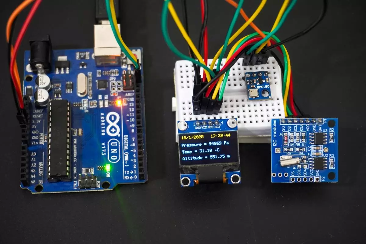
In this task, Arduino UNO acts as an I2C master, and the BMP180 sensor module, the OLED display, and the DS1307 RTC module act as slaves.
I²C Pins Of Arduino UNO
- SDA → A4
- SCL → A5
First, let's establish the hardware connection.
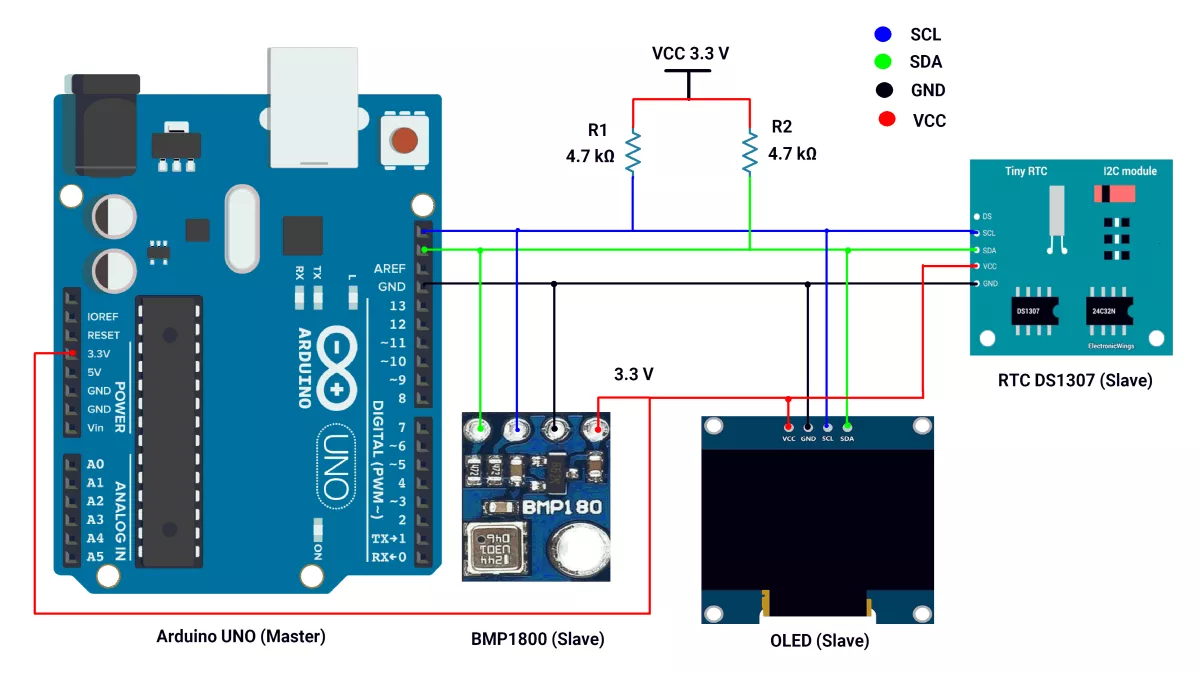
Arduino UNO Hardware Connection
- Connect A4 → SDA pin of the Slave.
- Connect A5 → SCL pin of the Slave.
- Ensure a shared GND between the Master and Slaves.
- Place 4.7 kΩ external pull-up resistors between VCC 3.3 V and each of the SDA and SCL lines.
- Connect the USB cable to the PC for power and UART communication.
Recommended practice: Power the DS1307 at 5 V and use an I²C level shifter for safe, reliable operation.
Circuit Diagram
Arduino UNO Firmware Implementation
- We will read the time and date from the RTC DS1307 and air pressure, temperature, and altitude data from the BMP180 sensor module and display them on the OLED display.
- We used Adafruit's SSD1306 library (available on GitHub) for the OLED, Adafruit_BMP085.h for the BMP180 sensor module, and RTClib.h by Adafruit for the RTC DS1307.
- For instructions on how to add a custom library to the Arduino IDE, refer to Adding Library to Arduino IDE.
Note: Adafruit_BMP085.h can be used for both the BMP085 and BMP180 Barometric Pressure sensor breakout boards.
Code of Arduino UNO as a master
#include <Wire.h>
#include <RTClib.h>
#include <Adafruit_GFX.h>
#include <Adafruit_SSD1306.h>
#include <Adafruit_BMP085.h>

#define oled_address 0x3C  // Define the I2C address of the OLED display

// Create an object to interface with the RTC module
RTC_DS1307 rtc;

// Create an object to interface with the BMP180 sensor
Adafruit_BMP085 bmp;

// Create an  object for OLED display (128x64 size)
#define SCREEN_WIDTH 128                                                   // Width of the display in pixels
#define SCREEN_HEIGHT 64                                                   // Height of the display in pixels
#define OLED_RESET -1                                                      // Define the reset pin for the OLED (not used in this case)
Adafruit_SSD1306 display(SCREEN_WIDTH, SCREEN_HEIGHT, &Wire, OLED_RESET);  // Initialize OLED display object


void setup() {

  Serial.begin(115200);

  // Initialize BMP180 sensor
  Serial.print("BMP180 sensor initializing...");

  // Wait until BMP180 sensor is initialized
  while (!bmp.begin()) {
    Serial.print(" .");
    delay(100);
  }
  Serial.println(" ");
  Serial.println("BMP180 sensor initialization complete.");

  // Check RTC DS1307 is successfully connected or not
  Serial.print("RTC Device scanning...");

  // Wait until RTC DS1307 is not found
  while (!rtc.begin()) {
    Serial.print(" .");
    delay(100);
  }
  Serial.println(" ");
  Serial.println("RTC device found");

  // Check if the OLED display is connected
  Serial.print("OLED display scanning...");
  Wire.beginTransmission(oled_address);  // Start I2C communication with OLED
  while (Wire.endTransmission()) {       // Check if the OLED responds
    Serial.print(".");
    delay(100);
  }
  Serial.println(" ");
  Serial.println("OLED display found");

  // Initialize OLED display
  Serial.print("OLED display initializing.....");

  // Initialize OLED display
  while (!display.begin(SSD1306_SWITCHCAPVCC, oled_address)) {
    Serial.print(" .");
    delay(100);
  }
  Serial.println(" ");
  Serial.println("OLED display initialization complete.");

  // Disable internal pull-ups on SDA/SCL
  pinMode(A4, INPUT);        // SDA
  pinMode(A5, INPUT);        // SCL
  digitalWrite(A4, LOW);     // ensure pull-up is off
  digitalWrite(A5, LOW);     // ensure pull-up is off

  delay(2000);  // Pause for 2 seconds after the initial setup

  // Clear the display and set up text parameters
  display.clearDisplay();
  display.setTextSize(1);
  display.setTextColor(SSD1306_WHITE);  // Set text color to white

  // Uncomment the line below to set time on RTC initially (if needed)
  // rtc.adjust(DateTime(F(__DATE__), F(__TIME__))); //Initialize the RTC with the compile-time date and time
}

void loop() {

  // Get the current time and date from RTC
  DateTime now = rtc.now();

  // Clear the display and start updating it
  display.clearDisplay();
  display.setCursor(0, 0);  //Set the cursor to the top-left corner (column 0, row 0) of the OLED display

  // display date top-left corner (Date/Month/Year)
  display.print(now.day(), DEC);
  display.print("/");
  display.print(now.month(), DEC);
  display.print("/");
  display.print(now.year(), DEC);

  display.setCursor(71, 0);  //Set the cursor to the top-left corner (column 71, row 0) of the OLED display

  // Display the current time(dec value) on top-right corner (hours:minutes:seconds)
  display.print(now.hour(), DEC);
  display.print(':');
  if (now.minute() < 10) {  // Add leading zero for minutes less than 10
    display.print('0');
  }
  display.print(now.minute(), DEC);
  display.print(':');

  if (now.second() < 10) {  // Add leading zero for seconds less than 10
    display.print('0');
  }
  display.print(now.second(), DEC);

  // Display atmospheric pressure value from BMP180 sensor (Unit = "Pa")
  display.setCursor(0, 16);  // Set the cursor to the (column 0, row 16) of the OLED display
  display.print("Pressure = ");
  display.print(bmp.readPressure());  // Read and display pressure in Pascals
  display.print(" Pa");

   // Display temperature value from BMP180 sensor(degree celcius(°C))
  display.setCursor(0, 32);  // Set the cursor to the (column 0, row 32) of the OLED display
  display.print("Temp = ");
  display.print(bmp.readTemperature());
  display.print(" ");
  display.write(248);
  display.print("C");

  // Calculate altitude(meter) assuming 'standard' barometric
  // pressure of 1013.25 millibar = 101325 Pascal
  display.setCursor(0, 48);  // Set the cursor to the (column 0, row 48) of the OLED display
  display.print("Altitude = ");
  display.print(bmp.readAltitude());
  display.print(" m");

  display.display();  // Update the OLED display with the new content

  // Wait for 1 second before updating again
  delay(1000);
}
Code Explanation
rtc.adjust(DateTime(F(__DATE__), F(__TIME__)));__DATE__and__TIME__are predefined macros in Arduino that represent the compile date and time of the code.- These values are based on the time when the code was compiled, not when it was uploaded.
rtc.adjust(DateTime(F(__DATE__), F(__TIME__)));sets the RTC to the time and date of the sketch compilation.- You can manually set the time with
rtc.adjust(DateTime(2025, 1, 16, 12, 0, 0));// to set the RTC to a specific date and time.
DateTime now = rtc.now();- Reads the current date and time from the RTC module. The now object stores the current time and date (hour, minute, second, day, month, and year).
bmp.readPressure();- Reads the pressure value from the BMP180 sensor in Pascals (Pa).
bmp.readAltitude();- Reads the altitude value from the BMP180 sensor in meters (m).
bmp.readTemperature();- Reads the temperature value from the BMP180 sensor in degrees Celsius (°C).
display.display();- Updates the OLED display to show the latest information (time and pressure).
Output
Hardware Setup
Video