88. Multi-Waveform Generator
In this task, we’re building a waveform generator using an ESP32 microcontroller.
We use ESP32's internal DAC to generate sine, square, and triangle waves.
Two potentiometers will be connected to GPIO 34 and 35 (ADC channels) of the ESP32.
The values from the ADC will control the amplitude and frequency, while a push button connected to GPIO 25 switches between waveforms (sine, triangle, square).
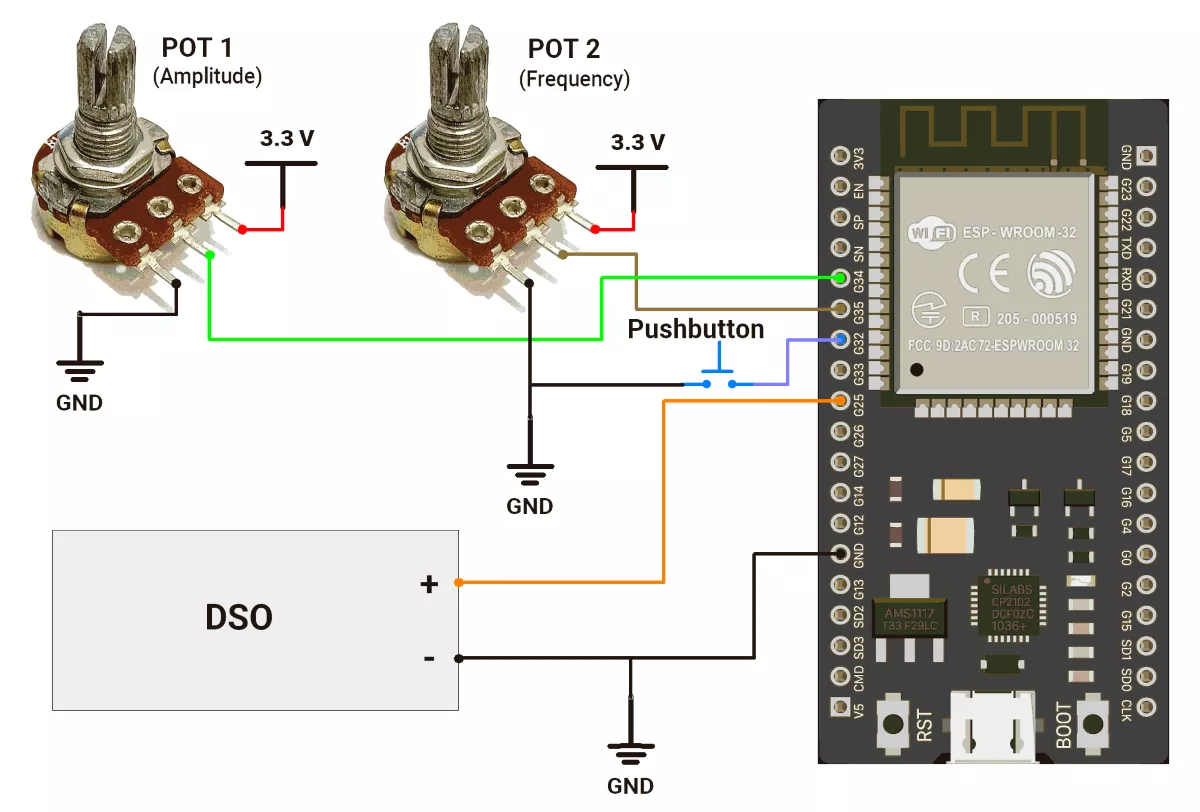
Hardware Connections
- Connect Potentiometer 1 to GPIO34 (ADC channel) for amplitude control
- Connect Potentiometer 2 to GPIO35 (ADC channel) for frequency control
- Connect the Pushbutton to GPIO32 with PULLUP for Switches between waveforms
- Connect oscilloscope to GPIO25 (DAC_PIN) to observe output
- Power the ESP32 via USB
Circuit Diagram
Firmware
The code performs three main tasks
- Read potentiometers every 100ms (non-blocking) to update amplitude and frequency.
- After pressing the push button, it switches the waveform type.
- Generate the selected waveform at a frequency determined by the user.
Code
#include <math.h>

#define DAC_PIN        25     // GPIO25 = DAC1
#define WAVE_SEL_PIN   32     // Push button to change waveform
#define AMP_POT_PIN    34     // Pot for amplitude
#define FREQ_POT_PIN   35     // Pot for frequency

enum Waveform { SINE, TRIANGLE, SQUARE };
Waveform currentWave = SINE;

uint8_t sineTable[256];

unsigned long lastPotReadTime = 0;
const unsigned long POT_READ_INTERVAL = 100000; // µs
unsigned long lastStepTime = 0;
long delaySteps = 0;

int waveIndex = 0;
bool triangleRising = true;

int amplitude = 127;       // Output from 0 to amplitude (0–255)
float frequency = 250.0;

int readAvg(int pin, int samples = 5) {
  int sum = 0;
  for (int i = 0; i < samples; i++) sum += analogRead(pin);
  return sum / samples;
}

void setup() {
  analogReadResolution(12);
  pinMode(WAVE_SEL_PIN, INPUT_PULLUP);

  // Generate sine lookup table (0 to 255)
  for (int i = 0; i < 256; i++) {
    sineTable[i] = round(127.5 * (1 + sin(2 * PI * i / 256.0)));  // Range: 0–255
  }
}

void loop() {
  unsigned long now = micros();

  // 1. Read amplitude & frequency every 100ms
  if (now - lastPotReadTime >= POT_READ_INTERVAL) {
    lastPotReadTime = now;

    int ampRaw = readAvg(AMP_POT_PIN);
    int freqRaw = readAvg(FREQ_POT_PIN);

    amplitude = map(ampRaw, 0, 4095, 1, 255);  // Full DAC range
    frequency = pow(10, 1 + 2 * (freqRaw / 4095.0)); // 10Hz–1000Hz

    delaySteps = 1000000L / (256 * frequency); // for 256 steps per cycle
  }

  // 2. Handle the waveform button
  static unsigned long lastDebounce = 0;
  if (digitalRead(WAVE_SEL_PIN) == LOW && millis() - lastDebounce > 200) {
    currentWave = (Waveform)((currentWave + 1) % 3);  // Only 3 waveforms
    lastDebounce = millis();
    Serial.print("Waveform: ");
    Serial.println(currentWave);
    waveIndex = 0;
    triangleRising = true;
  }

  // 3. Generate waveform (non-blocking)
  if (now - lastStepTime >= delaySteps) {
    lastStepTime = now;

    uint8_t output = 0;

    switch (currentWave) {
      case SINE:
        output = (sineTable[waveIndex] * amplitude) / 255;
        waveIndex = (waveIndex + 1) % 256;
        break;

      case TRIANGLE:
        if (triangleRising) {
          waveIndex++;
          if (waveIndex >= 255) triangleRising = false;
        } else {
          waveIndex--;
          if (waveIndex <= 0) triangleRising = true;
        }
        output = (waveIndex * amplitude) / 255;
        break;

      case SQUARE:
        output = (waveIndex < 128) ? amplitude : 0;
        waveIndex = (waveIndex + 1) % 256;
        break;
    }

    dacWrite(DAC_PIN, output);
  }
}
Code Explanation
We use an enum to represent the three waveform types: SINE, TRIANGLE, and SQUARE, starting with SINE by default.
We also have a 256-point sine table already calculated and stored for speed, so we don’t need to calculate sin() in real time.
setup() – Initial Config
- Analog read resolution is set to 12 bits (so we get values from 0–4095).
- The waveform select button is set as input with pull-up enabled.
- We fill the
sineTable[]with precomputed values from 0 to 255, scaling the sine function to match the DAC output range.
loop()– Main Logic
This loop is continuously doing three key things:
1. Reading Potentiometers Every 100ms
We don’t want to overload the processor reading pots constantly, so we read them every 100 milliseconds using micros().
- Amplitude Pot is mapped linearly from 0–4095 → 1–255.
- Frequency Pot is scaled exponentially for smoother low-frequency control:
frequency = pow(10, 1 + 2 * (freqRaw / 4095.0));
This gives finer control at low frequencies and faster changes at higher ones. - We then calculate
delaySteps, which is the delay between each of the 256 waveform samples:delaySteps = 1000000 / (256 * frequency);
2. Switching Waveforms via Button
If the button is pressed (active LOW) and at least 200 ms have passed since the last press (simple debounce), we cycle to the next waveform. It wraps around from SINE → TRIANGLE → SQUARE → SINE.
3. Generating the Waveform (Non-Blocking)
Every delaySteps microseconds, we output the next value of the waveform:
- SINE: We just grab the next value from the preloaded
sineTable[]and scale it by amplitude. - TRIANGLE: We increase or decrease a
waveIndexfrom 0–255 and back to simulate a linear up/down triangle wave. - SQUARE: Based on this
waveIndex, we either output full amplitude (for the first half of the wave) or zero.
Finally, we send the result to the DAC using:
dacWrite(DAC_PIN, output);
Output
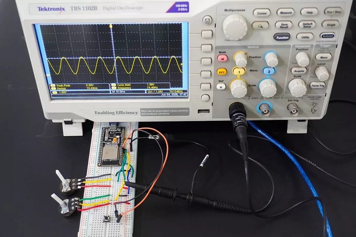
Video