89. Phase-shifted Sine Wave
In this Task, we have to generate 2 sine waveforms, and the second waveform will be phase-shifted.
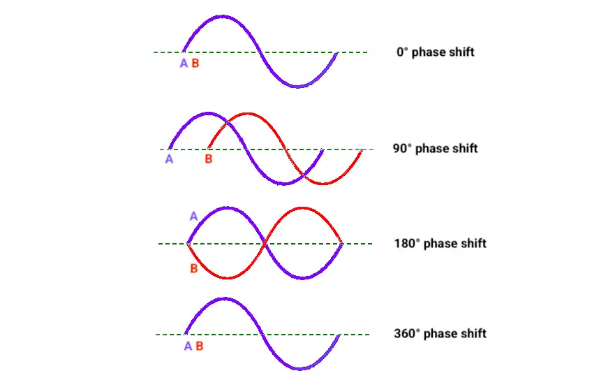
What is a Phase shift?
Phase shift refers to the time difference between two periodic signals of the same frequency.
Phase shift is measured in degrees 0° to 360°
Microcontrollers often implement it by delaying one waveform relative to another to create the desired phase shift offset.
In our task,
We will delay (phase shift) the sine waveform 2, based on the potentiometer's reading.
Which microcontroller are we using?
Since the ATmega328P (Arduino UNO) does not have a built-in DAC, we will use the ESP32 for this task.
While PWM can also be used to generate a sine wave (approximating an analog waveform), it needs extra filtering and does not offer the same accuracy or smoothness as a DAC.
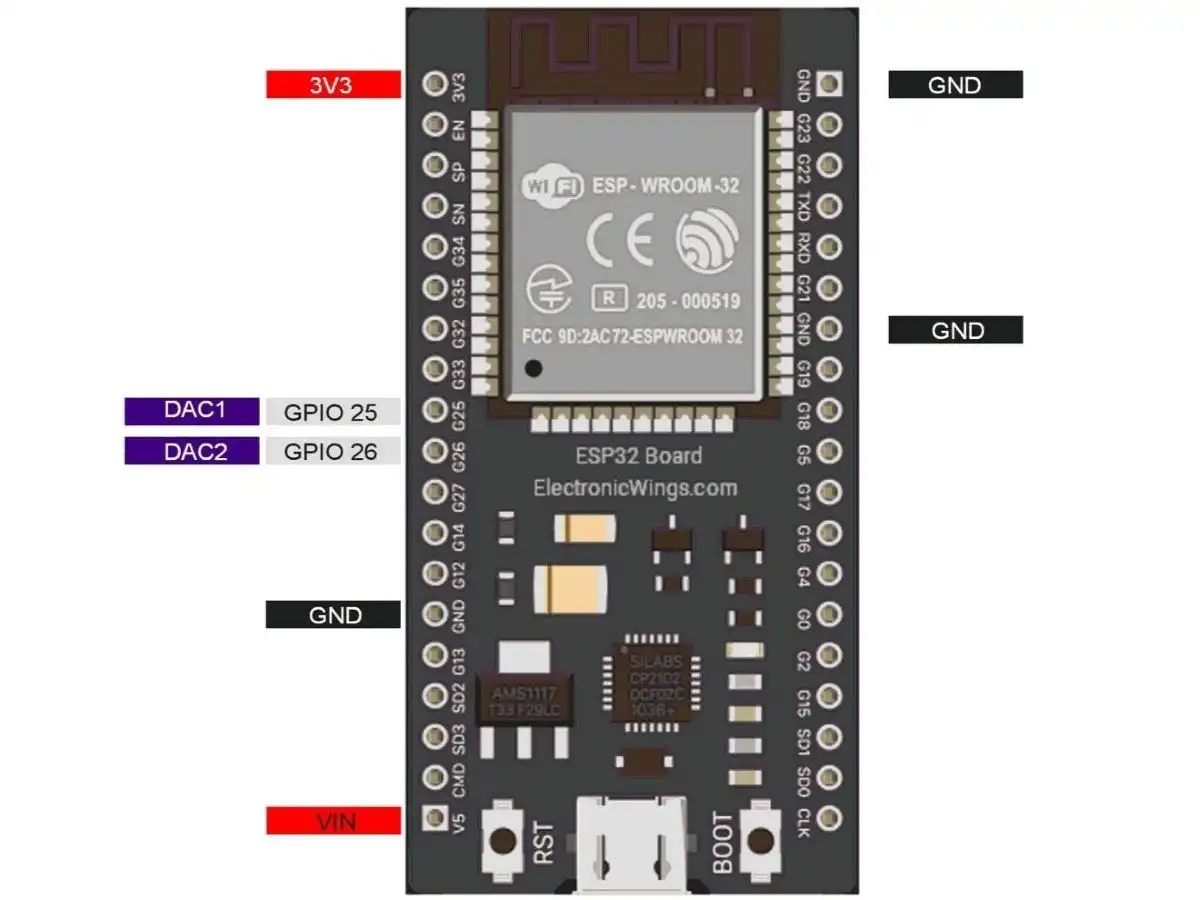
DAC in ESP32:
- ESP32 has two 8-bit DAC (digital to analog converter) channels internally, which are connected to GPIO25 (Channel 1) and GPIO26 (Channel 2).
- 8-bit DAC means, ESP32 can convert the digital input (0 to 255) to an equivalent analog output.
- With 3.3Volt, our ESP32 will provide the 0-volt for digital 0 and 3.3V for digital 255. However, in practice, output by DAC is a bit lower, i.e., max 3.25V for 255.
Note: The output of the ESP32's DAC is not perfectly linear, which may affect the accuracy and precision of the waveform.
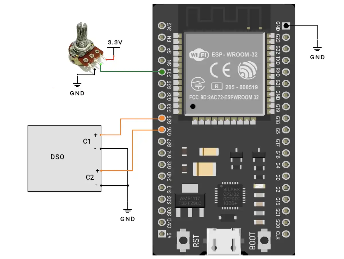
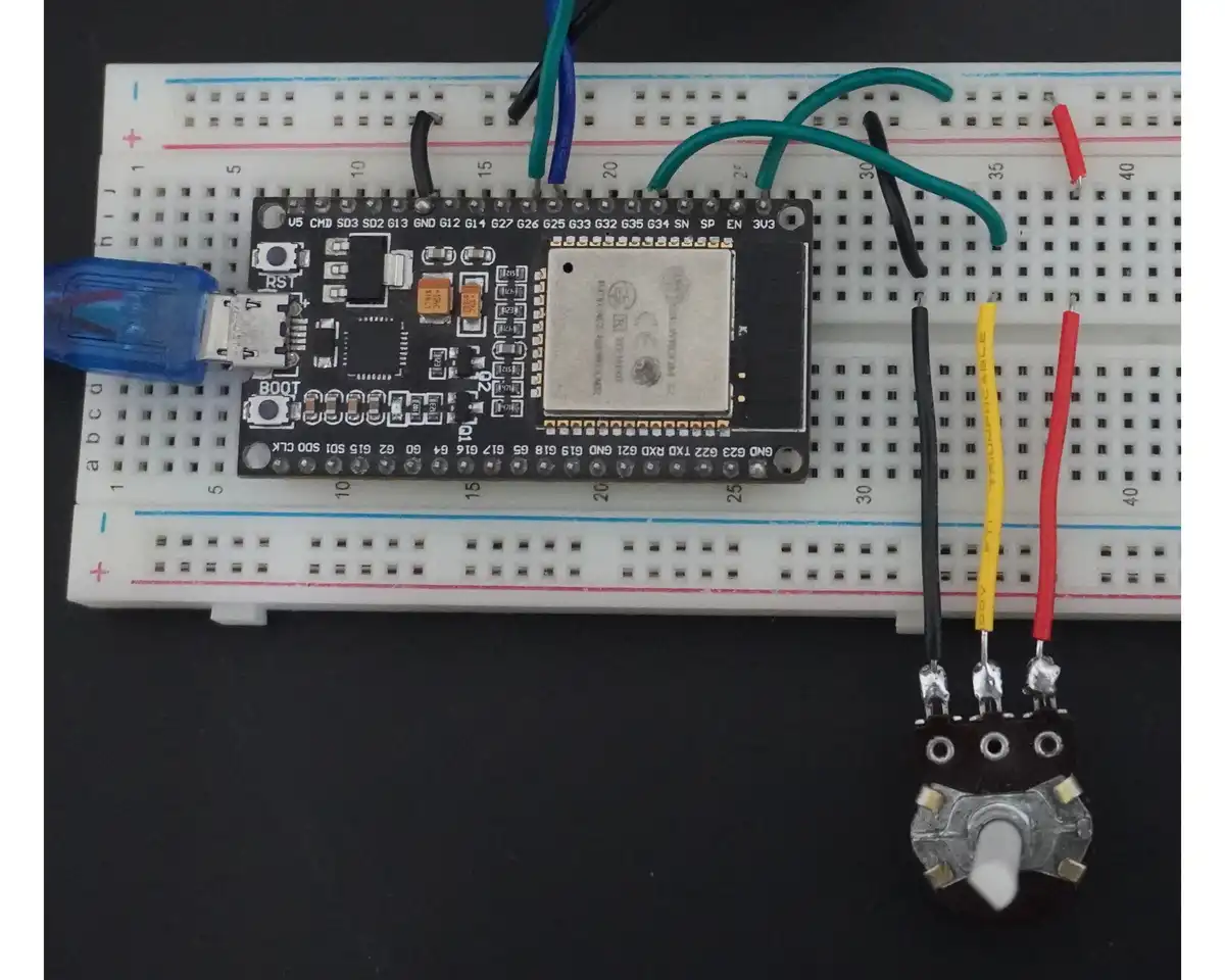
Hardware connections
The hardware connection is simple
Input
- Potentiometer → GPIO34
DAC Outputs: Connect to DSO.
- GPIO25 (DAC1) → Sine Wave 1 output
- GPIO26 (DAC2) → Sine Wave 2 output (phase-shifted)
Code
const int potPin = 34;          // ADC pin connected to potentiometer
const int dacPin1 = 25;         // DAC1
const int dacPin2 = 26;         // DAC2

const int waveformSize = 256;   // Size of sine wave table
uint8_t sineWave[waveformSize]; // 8-bit values for DAC

void generateSineWave() {
 for (int i = 0; i < waveformSize; i++) {
   float radians = (2 * PI * i) / waveformSize;
   sineWave[i] = (uint8_t)(127.5 + 127.5 * sin(radians)); // scale to 0–255
 }
}

void setup() {
 Serial.begin(115200);
 analogReadResolution(12);  // ESP32 supports 12-bit ADC
 generateSineWave();
}

void loop() {
 int potValue = analogRead(potPin); // Read potentiometer (0 to 4095)
 float phaseShift = (float)(potValue / 11.375); // Degrees (0–360)
 int phaseShiftSamples = (int)(phaseShift / 360.0 * waveformSize);

 for (int i = 0; i < waveformSize; i++) {
   int index1 = i;
   int index2 = (i + phaseShiftSamples) % waveformSize;

   dacWrite(dacPin1, sineWave[index1]);
   dacWrite(dacPin2, sineWave[index2]);

   delayMicroseconds(100); // Adjust for ~2s waveform total period
 }
}
Firmware
Generating the Sine Wave:
We will use the sin(angle) function, which returns the sine of an angle in radians. This value ranges from -1 to 1.
However, the ESP32's 8-bit DAC accepts values from 0 to 255
0 → 0V
255 → 3.3V
So, the sine values are converted from -1 to 1 into 0 to 255 using this formula: sineWave[i] = 127.5 + 127.5 * sin(angleInRadians);
To avoid repeating the same sine calculations in every cycle, we calculate them only once and store the values in the sineWave array.
Phase shift calculation:
We are using a 12-bit ADC (0 to 4095) to read the value of the potentiometer. So, potValue read from ADC is between 0 and 4095, which is converted to a range of 0 to 360 using the following formula.
float phaseShift = (float)potValue / 11.375;
Why 11.375?
It is the ratio of 4095.0 / 360 = 11.375
How to phase shift a signal?
To create a phase shift between two sine waves, we need to map the desired phase angle (from 0° to 360°) to an index range in the sineWave array (0 to 255).
This allows us to generate the second waveform with the required offset.
For example:
- 90° phase shift:
- Sine_waveform_1 = sineWave[0]
- Sine_waveform_2 = sineWave[64] (approximately, since 90° is 1/4th of 256 samples)
- 180° phase shift:
- Sine_waveform_1 = sineWave[0]
- Sine_waveform_2 = sineWave[128] (half a cycle ahead)
This method delays the second waveform by the required phase angle using pre-shifted index values in the array.
Below given formula is used for calculating the phase shift offset value and storing it into the phaseShiftSamples variable.
int phaseShiftSamples = (int)(phaseShift / 360.0 * waveformSize);
Circular Indexing
int index2 = (i + phaseShiftSamples) % waveformSize;
The % waveformSize part ensures we wrap around the sine array when the index exceeds 255.
Frequency Control
delayMicroseconds(100) sets the time between DAC updates, which controls the frequency of the waveform. Smaller delays mean higher frequency.
- 256 samples × 100 µs = ~25.6 ms per cycle → ~39 Hz sine wave.
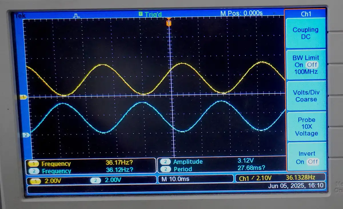
Output
Setup
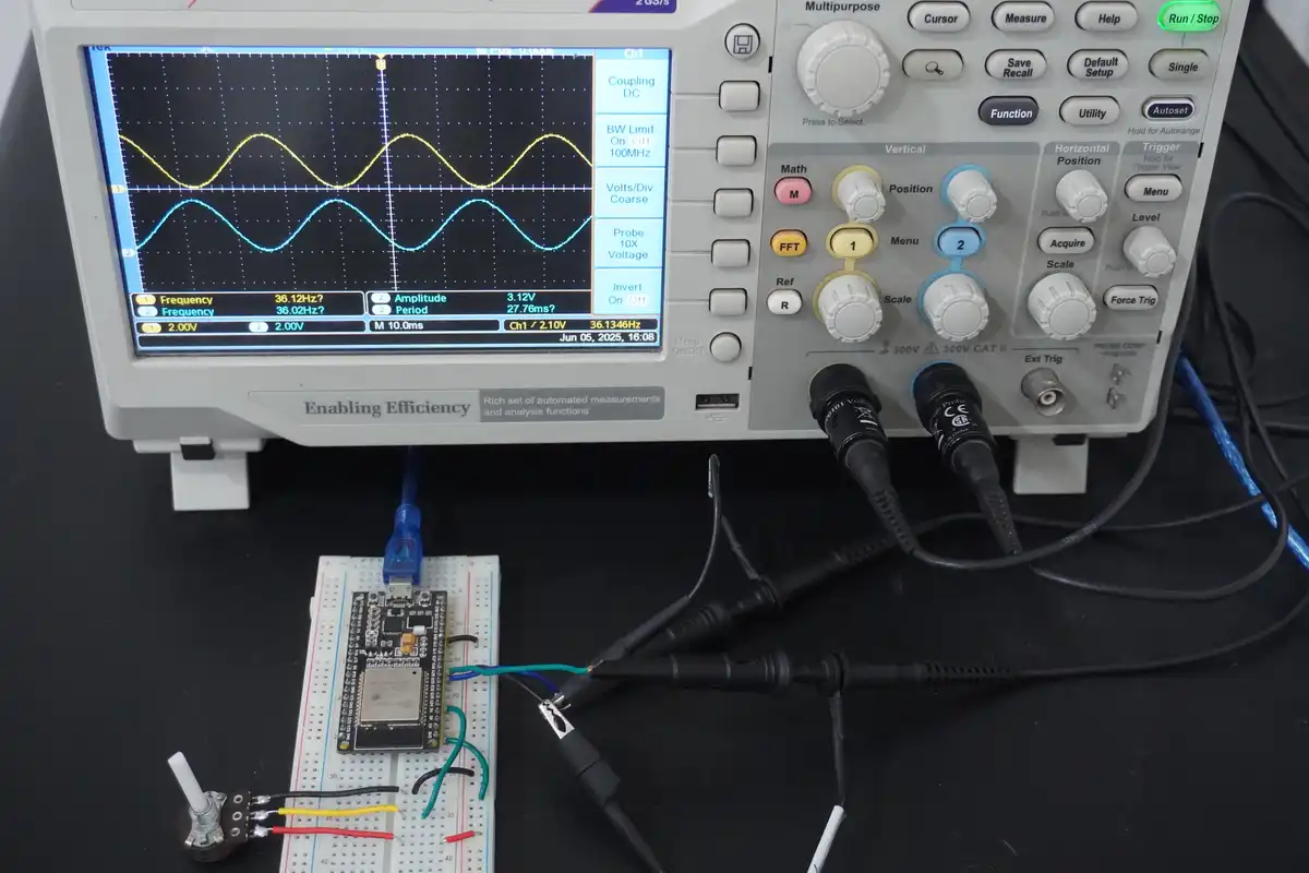
Circuit
Waveform
Video