27. Simple voltmeter using ADC
The goal is to read an analog voltage input using the microcontroller's ADC and convert it into a digital voltage value displayed over serial communication.
Understanding the Task
To implement a simple voltmeter, the microcontroller needs to:
- Sample the analog voltage on a designated ADC channel.
- Convert the ADC digital value to voltage units (Volts).
- Send the voltage reading to a serial terminal for user observation.
Hardware Interfacing
Voltage Input Connection
- Connect the voltage source's positive terminal to any ADC channel.
- Connect the voltage source negative terminal to GND on the board.
Note: The input voltage must be within the microcontroller’s GPIO voltage range to avoid damaging the microcontroller ADC pin.
Here, we will use a potentiometer as a varying voltage source.
Potentiometer Interfacing
We can use any of the potentiometers with values between 1kΩ and 10kΩ.
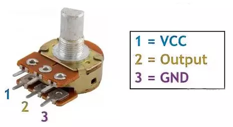
- Connection:
- Connect the two outer fixed terminals of the potentiometer to VCC and GND, and connect the middle (wiper) terminal to one of the microcontroller’s ADC (Analog-to-Digital Converter) input pins.
- Function:
- Rotating the potentiometer varies the middle terminal voltage from 0V to VCC, which the microcontroller’s ADC reads as a digital value proportional to the knob position.
So, by selecting a potentiometer as a voltage source, we can implement the task.
Below are the solutions to the given task using different microcontrollers
- STM32
- ESP32
- Arduino UNO
Simple Voltmeter using ADC Implementation on STM32
We’re using an STM32 NUCLEO-F103RB board, which runs at a 3.3V logic level.
Key Peripherals Used
- ADC1 Channel 0 (PA0): Reads the analog voltage from the potentiometer.
- USART2: For serial communication with a serial terminal to display voltage.
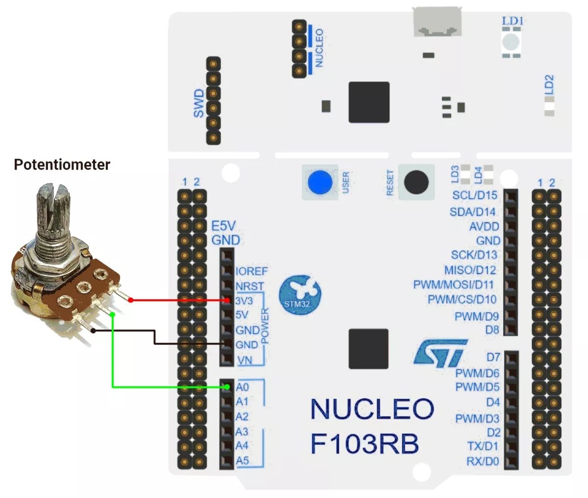
Hardware Connection
- Potentiometer connection:
- Connect the potentiometer’s middle pin (wiper) to PA0 (ADC1_IN0) for analog input.
- Connect the two outer pins of the potentiometer to 3.3V (VCC) and GND to form a voltage divider.
- Use a 10 kΩ potentiometer for best results.
- Use USART2 on the STM32 board for serial communication via the USB interface to display the measured voltage on a terminal.
Circuit Diagram
Firmware Implementation
Project Setup in STM32CubeIDE
- Create a Project
- Open STM32CubeIDE, start a new project, and select the NUCLEO-F103RB board.
- Basic Configuration (via CubeMX inside CubeIDE)
- Clock: Use the default HSI oscillator with PLL enabled (as configured in
SystemClock_Config). - GPIO: Enable clocks for PORTA, PORTB, PORTC, and PORTD.
- ADC1 (Analog Input Source)
- Resolution: 12-bit (0–4095 range).
- Conversion mode: Single, software-triggered.
- Channel: ADC_CHANNEL_0 (PA0).
- USART2: Enabled at 115200 baud, 8-N-1.
- Clock: Use the default HSI oscillator with PLL enabled (as configured in
- Code Generation
- CubeMX will automatically generate all the startup code, including:
HAL_Init()→ Initializes HAL and system tick.SystemClock_Config()→ Configures system clock (HSI + PLL).MX_GPIO_Init()→ Initializes GPIO ports.MX_USART2_UART_Init()→ Configures UART2.MX_ADC1_Init()→ Configures ADC1 for analog input.
- This code sets up the hardware and prepares the project for firmware development, so we only need to add our application logic in the user code sections
- CubeMX will automatically generate all the startup code, including:
Code Snippets from main.c
ADC Initialization (MX_ADC1_Init):
static void MX_ADC1_Init(void)
{
  ADC_ChannelConfTypeDef sConfig = {0};

  /** Common config
  */
  hadc1.Instance = ADC1;
  hadc1.Init.ScanConvMode = ADC_SCAN_DISABLE;
  hadc1.Init.ContinuousConvMode = DISABLE;
  hadc1.Init.DiscontinuousConvMode = DISABLE;
  hadc1.Init.ExternalTrigConv = ADC_SOFTWARE_START;
  hadc1.Init.DataAlign = ADC_DATAALIGN_RIGHT;
  hadc1.Init.NbrOfConversion = 1;
  if (HAL_ADC_Init(&hadc1) != HAL_OK)
  {
    Error_Handler();
  }

  /** Configure Regular Channel
  */
  sConfig.Channel = ADC_CHANNEL_0;
  sConfig.Rank = ADC_REGULAR_RANK_1;
  sConfig.SamplingTime = ADC_SAMPLETIME_13CYCLES_5;
  if (HAL_ADC_ConfigChannel(&hadc1, &sConfig) != HAL_OK)
  {
    Error_Handler();
  }

}
This configures ADC1 for single-channel operation with right-aligned 12-bit results.
UART2 Initialization (MX_USART2_UART_Init):
static void MX_USART2_UART_Init(void)
{
  huart2.Instance = USART2;
  huart2.Init.BaudRate = 115200;
  huart2.Init.WordLength = UART_WORDLENGTH_8B;
  huart2.Init.StopBits = UART_STOPBITS_1;
  huart2.Init.Parity = UART_PARITY_NONE;
  huart2.Init.Mode = UART_MODE_TX_RX;
  huart2.Init.HwFlowCtl = UART_HWCONTROL_NONE;
  huart2.Init.OverSampling = UART_OVERSAMPLING_16;
  if (HAL_UART_Init(&huart2) != HAL_OK)
  {
    Error_Handler();
  }
}
This configures USART2 for communication at a 115200 baud rate with 8 data bits, no parity, and 1 stop bit, supporting both transmit and receive.
Header includes, Private defines, and Private Variables:
The provided code defines cleaner code organization:
#include <string.h>

// ADC configuration
#define ADC_MAX_VALUE       4095    // 12-bit ADC maximum value
#define VOLTAGE_MAX_VALUE   3.3f    // Maximum voltage corresponding to ADC max value
#define ADC_TIMEOUT_MS      20      // ADC conversion timeout in milliseconds
#define SERIAL_DELAY_MS     2000    // Delay between serial transmissions

// ADC calibration values
#define LOW_RANGE_CALIB     0.050f  // Calibration offset for values < 1900
#define HIGH_RANGE_CALIB    0.040f  // Calibration offset for values < 4095
#define LOW_RANGE_THRESHOLD 1900    // Threshold for low range calibration

// Buffer for string conversions (optimized size)
static char conversion_buffer[16];
Utility Functions:
a) Convert float to string with specified decimal places
/**
  * @brief  Converts a float to a string with specified decimal places
  * @param  val: The float value to convert
  * @param  buffer: Pointer to the output buffer
  * @param  decimals: Number of decimal places to show
  * @retval None
  */
static void floatToStr(float val, char* buffer, uint8_t decimals) {
    int32_t whole = (int32_t)val;
    float fraction = val - whole;

    // Handle negative numbers
    if (val < 0) {
        fraction *= -1;
    }

    // Convert whole part
    int32_t n = whole;
    uint8_t i = 0;
    char temp[10]; // Temporary buffer for digit reversal

    if (n == 0) {
        buffer[i++] = '0';
    } else {
        if (n < 0) {
            buffer[i++] = '-';
            n = -n;
        }

        uint8_t j = 0;
        while (n > 0) {
            temp[j++] = (n % 10) + '0';
            n /= 10;
        }

        while (j > 0) {
            buffer[i++] = temp[--j];
        }
    }

    // Decimal point
    buffer[i++] = '.';

    // Fraction part
    for (uint8_t d = 0; d < decimals; d++) {
        fraction *= 10;
        uint8_t digit = (uint8_t)fraction;
        buffer[i++] = digit + '0';
        fraction -= digit;
    }

    buffer[i] = '\0'; // Null-terminate
}
b) Print string over UART
/**
  * @brief  Prints a string to the serial monitor
  * @param  msg: Pointer to the null-terminated string to send
  * @retval None
  */
static void printOnSerialMonitor(const char *msg) {
    HAL_UART_Transmit(&huart2, (uint8_t*)msg, strlen(msg), HAL_MAX_DELAY);
}
Main Loop - Reading and Displaying Voltage
  while (1) {
    // Start ADC conversion
    HAL_ADC_Start(&hadc1);

    // Wait for ADC conversion to complete
    HAL_ADC_PollForConversion(&hadc1, ADC_TIMEOUT_MS);
    // Read the converted ADC value (12-bit resolution)
    uint16_t adcValue = HAL_ADC_GetValue(&hadc1);

    // Calculate voltage from ADC value
    float voltageValue = (VOLTAGE_MAX_VALUE * adcValue) / ADC_MAX_VALUE;

    // Apply calibration offsets based on ADC range
    if (adcValue != 0) {
      if (adcValue < LOW_RANGE_THRESHOLD) {
        voltageValue += LOW_RANGE_CALIB;
      } else if (adcValue < ADC_MAX_VALUE) {
        voltageValue += HIGH_RANGE_CALIB;
      }
    }

    // Convert and display voltage value
    floatToStr(voltageValue, conversion_buffer, 3);
    printOnSerialMonitor("Voltage value: ");
    printOnSerialMonitor(conversion_buffer);
    printOnSerialMonitor(" \r\n");

    HAL_Delay(SERIAL_DELAY_MS); // Delay between readings
}- ADC Conversion
- Starts ADC conversion (
HAL_ADC_Start) to read the analog voltage from a sensor/potentiometer. - Waits for conversion to complete (
HAL_ADC_PollForConversion). - Reads the 12-bit ADC value (
0–4095).
- Starts ADC conversion (
- Voltage Calculation
- Converts the ADC value to a voltage (e.g.,
0–3.3V).
- Converts the ADC value to a voltage (e.g.,
- Calibration
- Adjusts the voltage with calibration offsets:
- Low-range correction (if ADC value is below
LOW_RANGE_THRESHOLD). - High-range correction (for other values).
- Low-range correction (if ADC value is below
- Adjusts the voltage with calibration offsets:
- Serial Output
- Formats the voltage as a string (
floatToStr). - Prints it via UART (
printOnSerialMonitor).
- Formats the voltage as a string (
- Delay
- Adds a small delay (
SERIAL_DELAY_MS) to stabilize readings and prevent serial flooding.
- Adds a small delay (
Download Project
The complete STM32CubeIDE project (including .ioc configuration, main.c, and HAL files) is available here:
📥 Download Project
We are using the ESP32 DevKitC v4 development board and programming it using the Arduino IDE
- Before uploading, make sure to select “ESP32 Dev Module” as the board to ensure correct settings and compatibility
If we analyze the task carefully,
- We need a varying voltage source. For this, we will use a potentiometer with a resistance range of 1k to 10k Ω.
- To print the measured voltage, we will use the Serial Monitor.
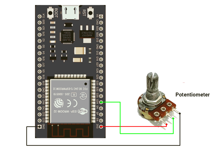
The circuit is connected as shown in the diagram below.
Circuit connection
- Connect the Potentiometer with GPIO pin 34 of the ESP32
Circuit Diagram
Firmware Implementation
Let us write the code for this voltmeter setup. It is very straightforward :
- Read the analog value
- Convert analog value to voltage
- Print on the Serial monitor
Code
#define adc_pin 34

void setup() {
  Serial.begin(115200);

  analogReadResolution(12);         // 0–4095
  analogSetAttenuation(ADC_11db);   // allows ~0–3.3V input range
  // or analogSetPinAttenuation(pin, ADC_11db); for specific pin
}

void loop() {
  int raw = analogRead(adc_pin);
  float voltage = (raw / 4095.0) * 3.3;
   Serial.print("  Voltage : ");
  Serial.println(voltage, 3);
  delay(2000);
}
Code Explanation
We will be using GPIO 34 as the analog input pin for voltage measurement.
1. analogRead(adc_pin)
Reads the analog voltage on GPIO 34 and returns a 12-bit ADC value
Range: 0 → 4095 (corresponding to 0V → 3.3V)
2. analogSetAttenuation(ADC_11db)
Enables the ESP32 ADC to measure voltages up to ~3.
3. float voltage = (raw / 4095.0) * 3.3
Converts the ADC value into actual voltage
- raw / 4095.0 → gives a 0–1 ratio
- Multiply by 3.3 to get the voltage in volts
4. Serial.print / Serial.println
Displays the measured voltage on the Serial Monitor.
ESP32 ADC Observation
As we know, the ADC gives a linear response proportional to the input. But in the ESP32, we have observed that it gives a non-linear response.
The responsive curve is shown in the chart below.
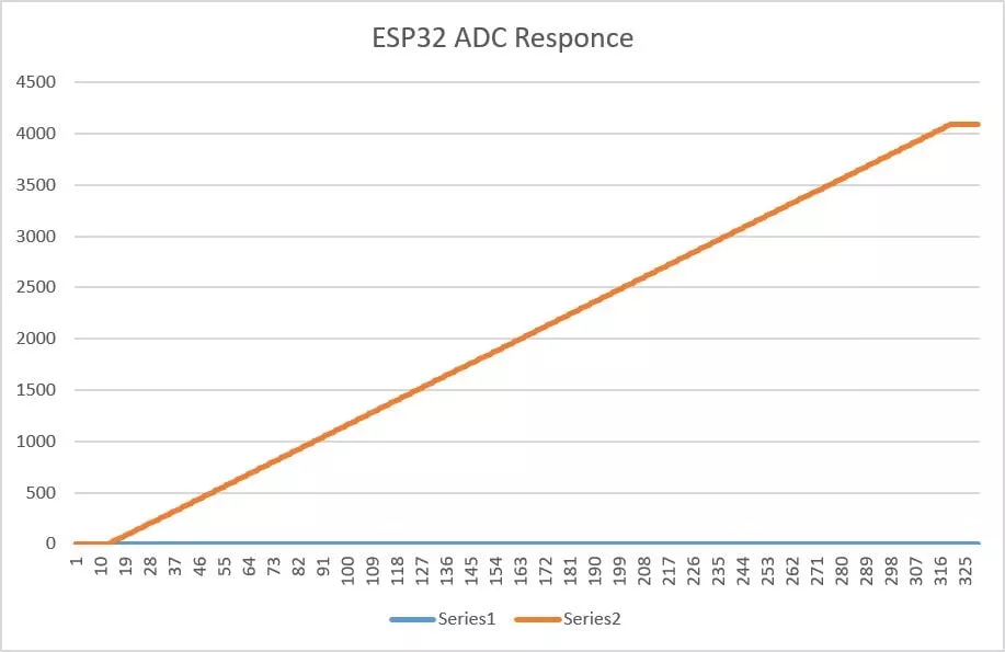
Due to this nonlinear behavior, when increasing the voltage from 0 to 3.3 V, the ADC keeps reading 0 until about 0.138 V — this is the dead zone.
When decreasing the voltage from 3.3 V to 0, the ADC stays at 4095 until about 3.21 V — this is the saturation zone.
Only between ~0.138 V and ~3.21 V does the ADC respond normally.
Accuracy of ESP32 Voltmeter
To calculate the accuracy error, we use:
Error(%) = ( |Vactual - Vmeasured | / Vmeasured ) x 100
Based on the measured behavior of the ESP32 ADC:
Linear Region (0.12 V → 3.12 V)
- ESP32 ADC typical error: ±5–8%
- So accuracy is roughly: 92% to 95%
Dead Zone (0 V → 0.12 V)
- ADC always reads 0
- Example: actual = 0.10 V, measured = 0 V
- So accuracy is 0%.
Saturation Zone (3.12 V → 3.30 V)
- Above ~3.12 V, the ESP32 ADC stays fixed at 4095, meaning it cannot measure higher voltages. This saturation makes the entire upper range inaccurate.
We are using the Arduino UNO development board and programming it using the Arduino IDE.
- Before uploading, make sure to select “Arduino UNO” as the board to ensure correct settings and compatibility.
If we analyze the task carefully,
- We need a varying voltage source. For this, we will use a potentiometer with a resistance range of 1k to 10k Ω.
- To print the measured voltage, we will use the Serial Monitor.
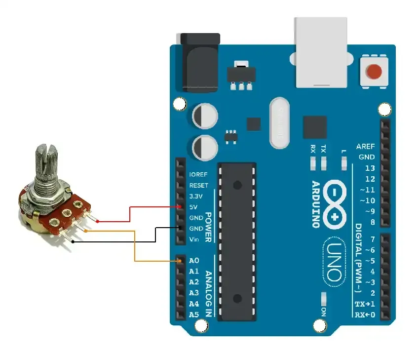
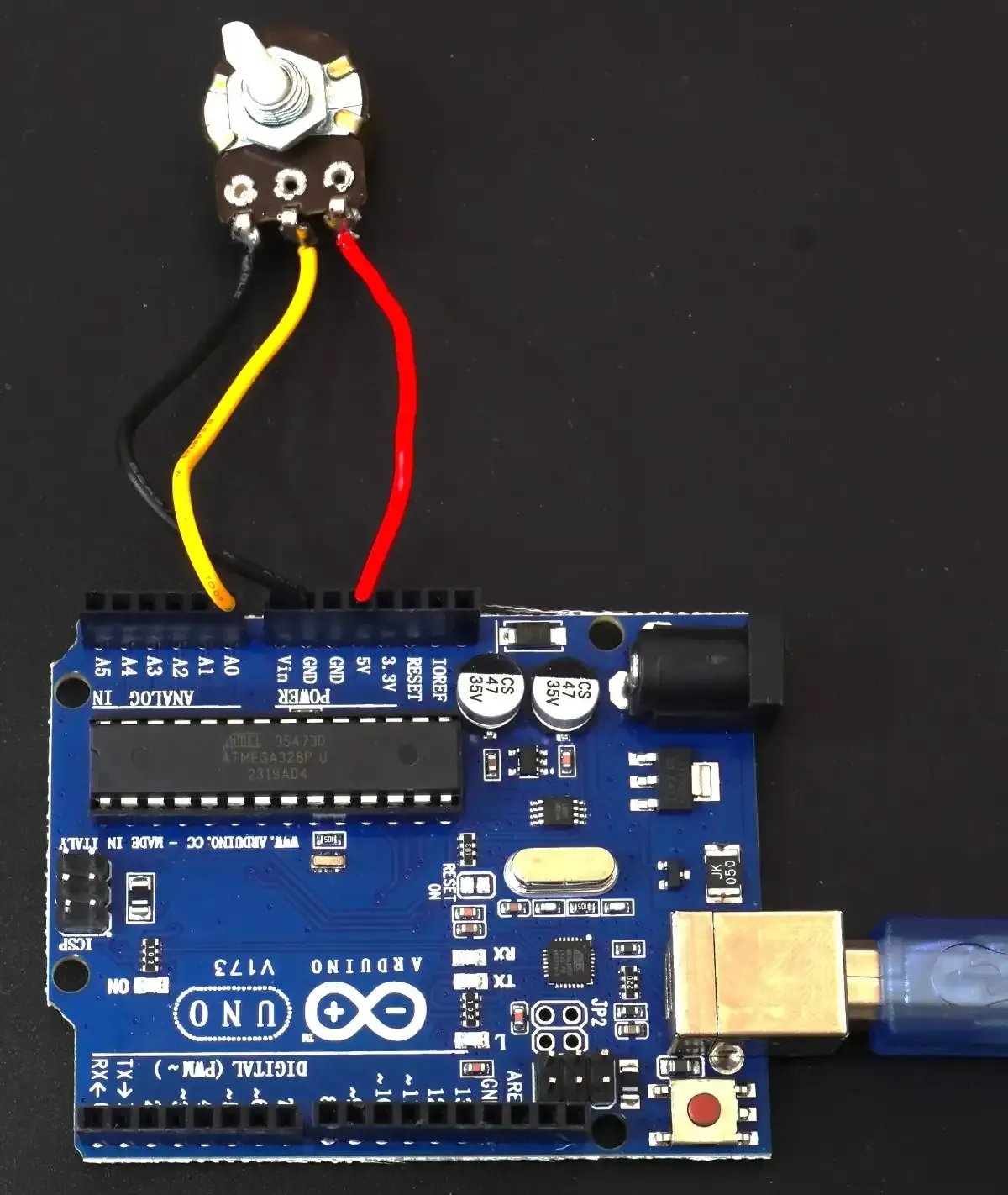
The circuit is connected as shown in the diagram below.
Arduino UNO Circuit connection
Connection
Firmware Implementation
Let us write the code for this voltmeter setup. It is very straightforward :
- Read the analog value
- Convert analog value to voltage
- Print on the Serial monitor
Code
// Pin for analog input
const int analogPin = A0;

void setup() {
  Serial.begin(9600);
}

void loop() {
  // Read the raw ADC value (10-bit resolution: 0 to 1023)
  int adcValue = analogRead(analogPin);
  // Convert the ADC value to voltage
  // 5V reference, voltage = (adcValue * 5.0) / 1023
  float voltage = adcValue * (5.0 / 1023.0);
  // Print the ADC value and corresponding voltage
  Serial.print("ADC Value: ");
  Serial.print(adcValue);
  Serial.print(" | Voltage: ");
  Serial.print(voltage);
  Serial.println(" V");
  // Wait for a short time before taking another reading
  delay(500);  // 500ms delay
}
Code explanation
- We will be using an A0 pin for voltage measurement.
- The code performs the following tasks, which are listed with their respective functions:
analogRead(analogPin):reads ADC value.float voltage=adcValue * (5.0 / 1023.0): converts ADC_value to voltage.Serial.print: print ADC_value and Voltage.
Output
The circuit connection is as follows
The output of the voltmeter readings is as follows
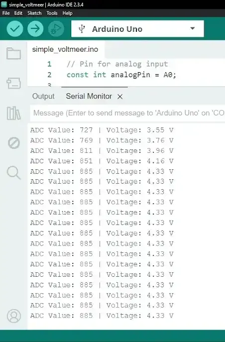
- As we can see in the video, the Voltage change is successfully detected and printed on the Serial monitor.
Limitations
- Our voltmeter can measure with an accuracy of +- 4.88 mV. To improve voltmeter accuracy, we need to use an ADC with higher resolution.
- The potentiometer output pin produces 0V (GND); it is not exactly 0V. Some current flows and ADC readings randomly shift from 0 to 1 (around 5 mV fluctuations).