78. Simultaneous Blinking LEDs
Every embedded engineer's journey begins with blinking an LED, but professional applications demand much more sophistication. When you need multiple LEDs blinking at different precise intervals while your microcontroller handles critical tasks, you need robust solutions that don't compromise system performance.
Using Hardware Timer Interrupts
Why this Approach Works Best
After implementing dozens of industrial control systems, I've found that hardware timers provide the perfect balance of precision and efficiency. They work like precision Swiss watches inside your microcontroller, completely independent of your main program flow.
Single Timer Implementation (Most Resource-Efficient)
How it Works:
- Configure one timer to generate regular interrupts (e.g., every 1ms)
- Maintain separate counters for each LED in the interrupt service routine (ISR)
- Toggle LEDs when their respective counters reach target values
Best For:
- Resource-constrained devices
- Systems with limited available timers
- Applications where minor timing coupling is acceptable
Pro Tip: I always use a base interval that's the greatest common divisor of all required blink rates. For 100ms and 360ms, 20ms works perfectly.
Multiple Timer Method (Maximum Independence)
When to Choose This:
- When absolute timing independence is critical
- For safety-critical systems where failure isolation matters
- When working with microcontrollers that have multiple timers
Implementation Insight:
- Assign dedicated timers to each LED
- Configure each timer's compare match for the exact required interval
- Keep ISRs ultra-simple – just pin toggling
Comparative Analysis
| Feature | Single Timer | Multiple Timers |
| Resource Usage | Low | Higher |
| Timing Precision | Excellent | Perfect |
| Implementation Complexity | Moderate | Simple |
| Scalability | Good | Limited |
| Debugging Ease | Challenging | Straightforward |
Calculating Timer Values
The golden formula I use:
Compare_Value = (Desired_Interval * Clock_Frequency) / Prescaler - 1Handling Long Intervals
For intervals exceeding timer maximums:
- Use a prescaled 16-bit timer
- Implement a secondary counter in the ISR
- Consider using the timer overflow interrupt
So, by choosing any of the approaches and considering the above points, we can implement the task.
Below are the solutions to the given task using different microcontrollers
- STM32
- ESP32
- Arduino UNO
We’re using an STM32 NUCLEO-F103RB board.
As we have to blink only two LEDs, and we have two hardware timers available to use.
We will use a simple approach of using two different hardware timers for each LED.
Key Peripherals Used:
- TIM2: Time interval for LED1
- TIM3: Time interval for LED2
- GPIO: To connect LED1 and LED2
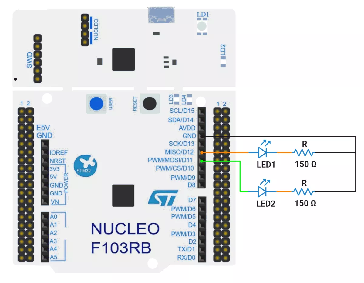
STM32 Hardware Connection
- Connect the anode of the LED1 to GPIO pin PA6(D12) and the cathode to GND through a current-limiting resistor.
- Connect the anode of the LED2 to GPIO pin PA7(D11) and the cathode to GND through a current-limiting resistor.
- Connect the STM32 NUCLEO-F103RB board to the PC via USB cable for Power.
Circuit Diagram:
STM32 Firmware Implementation
To hit 100 ms and 360 ms cleanly, pick a convenient counter tick (e.g., 1 ms), derive the prescaler from the timer input clock, then compute the auto-reload (ARR). This keeps the architecture simple, deterministic, and easy to audit.
Step 1 — Identify the timer input clock (f_TIM)
- On STM32, each timer sees a clock derived from the APB domain.
- If APB prescaler > 1, many STM32 parts double the timer clock (f_TIM = 2 × f_APB).
- Two common cases we’ll encounter in F1 projects:
- f_TIM = 72 MHz
- f_TIM = 64 MHz
Step 2 — Choose an easy tick rate
- Target 1 ms per tick (1 kHz counter rate). It makes math trivial and values small.
- You could also pick 0.5 ms or 10 ms, but 1 ms balances resolution with ISR load nicely.
Step 3 — Compute Prescaler (PSC)
Formula:
PSC = (f_TIM / f_tick) − 1where f_tick = 1 kHz for a 1 ms tick.
- If f_TIM = 72 MHz → PSC = (72,000,000 / 1,000) − 1 = 72,000 − 1 = 71,999
- If f_TIM = 64 MHz → PSC = (64,000,000 / 1,000) − 1 = 64,000 − 1 = 63,999
Step 4 — Compute Period / ARR for target intervals
General formula (up-counting mode):
Update_Period = ((PSC + 1) × (ARR + 1)) / f_TIMRearrange for ARR when tick is 1 ms:
ARR = (Desired_ms / 1 ms) − 1 = Desired_ms − 1- For 100 ms → ARR = 100 − 1 = 99
- For 360 ms → ARR = 360 − 1 = 359
Step 5 — Validate against timer width
- TIM2/TIM3 on STM32F1 are 16-bit → ARR must be ≤ 65,535.
- Our values (99, 359) are well within limits—green light.
Worked Configurations
- Case A: f_TIM = 72 MHz
- PSC = 71,999; ARR(100 ms) = 99; ARR(360 ms) = 359
- Case B: f_TIM = 64 MHz
- PSC = 63,999; ARR(100 ms) = 99; ARR(360 ms) = 359
Why this works
- PSC enforces a 1 ms tick cadence.
- ARR counts how many 1 ms ticks to accumulate before update: 100 or 360.
- Interrupt occurs at each update event → exact 100 ms/360 ms periodicity.
Project Setup in STM32CubeIDE
- Create a Project
- Open STM32CubeIDE and start a new project, select the NUCLEO-F103RB board.
- Basic Configuration (via CubeMX inside CubeIDE)
- Clock:
- Go to the Clock Configuration tab.
- Confirm APB1 Timer Clock is 64 MHz.
- If APB1 prescaler > 1, STM32F1 timers automatically get doubled clock (e.g., APB1 = 32 MHz → timer = 64 MHz).
- This is important because Prescaler values depend on the timer clock.
- GPIO:
- In Pinout & Configuration view:
- Select PA6 and PA7 in the chip diagram.
- Set both to GPIO_Output mode.
- In Pinout & Configuration view:
- Enable TIM2 and TIM3
- Clock:
- Go to Pinout & Configuration view.
- Under Timers:
- Enable TIM2 → Mode: Internal Clock
- Enable TIM3 → Mode: Internal Clock
- Configure TIM2 (100 ms)
- Click TIM2 in the left panel.
- Under Parameter Settings:
- Prescaler = 63999
- Counter Mode = Up
- Counter Period (ARR) = 99
- Clock Division = Div1
- Auto-Reload Preload = Disable (for fixed timing)
- Interrupt: Enable TIM2 Global Interrupt in NVIC.
- Configure TIM3 (360 ms)
- Click TIM3 in the left panel.
- Under Parameter Settings:
- Prescaler = 63999
- Counter Mode = Up
- Counter Period (ARR) = 359
- Clock Division = Div1
- Auto-Reload Preload = Disable
- Interrupt: Enable TIM3 Global Interrupt in NVIC.
- Code Generation
- CubeMX will automatically generate all the startup code, including:
HAL_Init()– Initializes the HAL library.SystemClock_Config()– Configures the system clock.MX_USART2_UART_Init()→ Sets up USART2.MX_GPIO_Init()– Configures PA6 and PA7 as outputs.MX_TIM2_Init()– Sets up TIM2 for 100 ms interrupts.MX_TIM3_Init()– Sets up TIM3 for 360 ms interrupts.
- This code sets up the hardware and prepares the project for firmware development, so we only need to add our application logic in the user code sections
- CubeMX will automatically generate all the startup code, including:
Code Snippets from main.c
GPIO Initialization (MX_GPIO_Init)
GPIO_InitStruct.Pin = GPIO_PIN_6 | GPIO_PIN_7;
GPIO_InitStruct.Mode = GPIO_MODE_OUTPUT_PP;
GPIO_InitStruct.Pull = GPIO_NOPULL;
GPIO_InitStruct.Speed = GPIO_SPEED_FREQ_LOW;
HAL_GPIO_Init(GPIOA, &GPIO_InitStruct);- Purpose: Configures PA6 and PA7 as digital outputs for controlling LEDs.
Timer Initialization
TIM2 – 100 ms Period
htim2.Instance = TIM2;
htim2.Init.Prescaler = 64000 - 1;  // 1 ms tick
htim2.Init.CounterMode = TIM_COUNTERMODE_UP;
htim2.Init.Period = 100 - 1; // 100 ms overflow- Purpose: Generates an interrupt every 100 ms for LED1.
- Details:
- Prescaler: CPU clock (64 MHz) ÷ 64000 = 1 kHz → 1 ms timer tick.
- Period: 100 ticks → 100 ms between interrupts.
TIM3 – 360 ms Period
htim3.Instance = TIM3;
htim3.Init.Prescaler = 64000 - 1;  // 1 ms tick
htim3.Init.CounterMode = TIM_COUNTERMODE_UP;
htim3.Init.Period = 360 - 1; // 360 ms overflow- Purpose: Generates an interrupt every 360 ms for LED2.
- Details: Same prescaler as TIM2, but longer period for slower blink.
LED Pin Definitions
#define LED1_PORT GPIOA
#define LED1_PIN  GPIO_PIN_6
#define LED2_PORT GPIOA
#define LED2_PIN GPIO_PIN_7- Purpose: Improves code readability by using names instead of raw pin numbers.
Timer Interrupt Callback
void HAL_TIM_PeriodElapsedCallback(TIM_HandleTypeDef *htim) {
    if (htim->Instance == TIM2)
        HAL_GPIO_TogglePin(LED1_PORT, LED1_PIN); // Blink LED1
    if (htim->Instance == TIM3)
        HAL_GPIO_TogglePin(LED2_PORT, LED2_PIN); // Blink LED2
}- Purpose: Executes automatically on timer overflow to toggle LEDs.
- Details:
- Checks which timer triggered the interrupt.
- Toggles the respective LED.
Starting the Timers
HAL_TIM_Base_Start_IT(&htim2); // Enable TIM2 interrupts
HAL_TIM_Base_Start_IT(&htim3); // Enable TIM3 interrupts
Purpose: Begins counting for both timers in interrupt mode.
Main Loop
while (1) {
    // All LED control handled in interrupts
}- Purpose: The Main loop is empty because LED blinking is entirely interrupt-driven.
Flow of Operation
- GPIO Setup → Configures
PA6andPA7as outputs. - Timers Configured →
TIM2(100 ms),TIM3(360 ms). - Timers Started in Interrupt Mode → Begin generating periodic events.
- Interrupt Callback → Toggles LEDs when each timer overflows.
- Main Loop → No LED control code needed; hardware timers handle timing.
Download Project
The complete STM32CubeIDE project (including .ioc configuration, main.c, and HAL files) is available here:
📥 Download Project
We are using the ESP32 DevKit v4 development board and programming it using the Arduino IDE.
- Before uploading, make sure to select “ESP32 Dev Module” as the board to ensure correct settings and compatibility.
ESP32 Timers
- ESP32 has 2 timer groups with 2 timers each → total 4 hardware timers.
- They have 64-bit counters with 16-bit prescalers to divide the 80 MHz clock (÷2 to ÷65536), giving flexible timer speeds.
- Timers can count up or down.
Since ESP32 has 4 hardware timers, we’ll use two of them, one for each LED, by assigning a separate timer interrupt to control each blink.
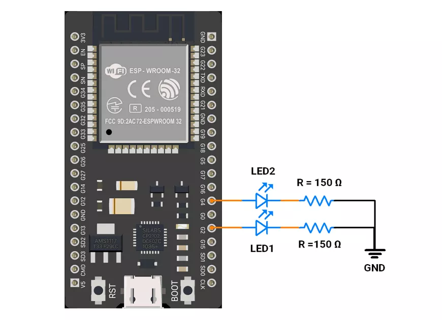
ESP32 Circuit Connection
- Interface the LED to the GPIO pins 2 and 4 with a 150 Ω resistor.
ESP32 Firmware Implementation
In the given code
- Timer1 toggles LED1 every 100 ms (100,000 µs).
- Timer2 toggles LED2 every 360 ms (360,000 µs).
ESP32 Code
#include <Arduino.h>

// LED pins
#define LED1_PIN 2  // LED1 toggles every 100 ms
#define LED2_PIN 4  // LED2 toggles every 360 ms

// Timer handles
hw_timer_t *timer1 = NULL;
hw_timer_t *timer2 = NULL;

// LED states
volatile bool led1State = false;
volatile bool led2State = false;

// ISR for LED1
void IRAM_ATTR onTimer1() {
  led1State = !led1State;
  digitalWrite(LED1_PIN, led1State);
}

// ISR for LED2
void IRAM_ATTR onTimer2() {
  led2State = !led2State;
  digitalWrite(LED2_PIN, led2State);
}

void setup() {
  // Initialize LED pins
  pinMode(LED1_PIN, OUTPUT);
  pinMode(LED2_PIN, OUTPUT);

  // Timer1: 1 MHz frequency, toggles LED1 every 100 ms → 100000 us
  timer1 = timerBegin(1000000);
  timerAttachInterrupt(timer1, &onTimer1);
  timerAlarm(timer1, 100000, true, 0);  // 100 ms

  // Timer2: 1 MHz frequency, toggles LED2 every 360 ms → 360000 us
  timer2 = timerBegin(1000000);
  timerAttachInterrupt(timer2, &onTimer2);
  timerAlarm(timer2, 360000, true, 0);  // 360 ms

}

void loop() {
  // Empty: all LED toggling handled by ISRs
}
Code Explanation
Let's understand the important function
hw_timer_t *timerX- Purpose: ESP32 has 4 hardware timers (0–3). This pointer stores a handle to whichever hardware timer you’re using.
- Here: Two separate timers are allocated — one to control LED1 and another for LED2.
- In code:
hw_timer_t *timer1 = NULL;
hw_timer_t *timer2 = NULL;
timerBegin(freq)- Purpose: Initializes a hardware timer with a base clock frequency.
- Here: Both timers are set to 1 MHz (1 tick = 1 µs).
- In code:
timer1 = timerBegin(1000000);
timer2 = timerBegin(1000000);
timerAttachInterrupt(timer, function)- Purpose: Links a hardware timer to an Interrupt Service Routine (ISR). When the timer counts up to its set alarm value, this function (ISR) runs.
- Here:
onTimer1()→ toggles LED1.onTimer2()→ toggles LED2.
- In code:
timerAttachInterrupt(timer1, &onTimer1);
timerAttachInterrupt(timer2, &onTimer2);
So each LED has its own “callback” that runs automatically.
timerAlarm(timer, value, autoreload, count)- Purpose: Sets a compare/alarm value (in ticks) at which the ISR will be triggered.
- Parameters:
value→ how many ticks before triggering (1 tick = 1 µs in given code).autoreload→ if true, repeats forever (like periodic interrupts).count→ initial count (usually 0).
- Here
100000ticks = 100 ms → LED1 toggles every 100 ms.360000ticks = 360 ms → LED2 toggles every 360 ms.
IRAM_ATTR- Purpose: Tells the compiler to put the ISR in IRAM (Internal RAM), so it can run quickly without being delayed by flash memory access.
- Here: This is required for ESP32 timer ISRs to avoid crashes or missed interrupts.
- In code:
void IRAM_ATTR onTimer1() { … }void IRAM_ATTR onTimer2() { … }
volatiletells the compiler a variable may change unexpectedly (e.g., in an ISR), so it prevents optimization that could ignore updates.
We are using the Arduino UNO development board and programming it using the Arduino IDE.
- Before uploading, make sure to select “Arduino UNO” as the board to ensure correct settings and compatibility.
Using tone() function:
We can use the tone() function for toggling LEDs. However, it has some limitations
tone()function generates frequency on only 1 pin at a time.tone()function can generate a lowest frequency of 31 Hz.
So we will use Timer1 and Timer2 for toggling of pins.
Using Timers:
- From the given problem statement, we can understand that:
- The controller will be busy in a
void loop(). - We need to blink 2 LEDs at different intervals while it is blocked in a void loop.
- The controller will be busy in a
- To achieve blinking, we can use Timers and Interrupts (Timer1 and Timer2).
- We will also connect the 2 LEDs on Pins 9 and 10, respectively.
- We will use the CTC mode of timers for our solution and the associated interrupt.
- We will do the following:
- Timer1 for LED1 (100ms Interval)
- CTC Mode is enabled using (
1 << WGM12). - Prescaler of 256 makes Timer1 count at
62.5 kHz(16MHz/256). - OCR1A Calculation for 100ms:
OCR1A=(100×(16000000/256)/1000)−1=6249
ISR (TIMER1_COMPA_vect)toggles LED1 every 100ms.
- CTC Mode is enabled using (
- Timer2 for LED2 (360ms Interval)
- CTC Mode is enabled using (
1 << WGM21). - Timer2 is an 8-bit timer, so
OCR2Amust be≤ 255. - The maximum time before Timer2 overflows is: 255 * 64us =
16.32 ms - This is much shorter than the required 360ms.
- Solution: Use
OCR2A = 155to generate an interrupt every ~10ms, then use a software counter to count 36 interrupts to reach 360 ms.
- CTC Mode is enabled using (
- Timer1 for LED1 (100ms Interval)
Arduino UNO Circuit Connection
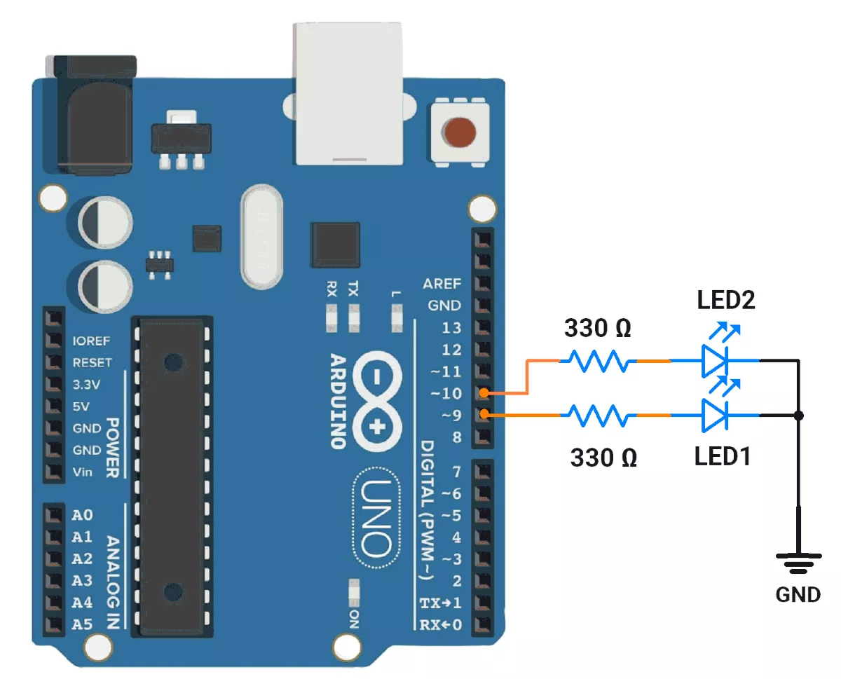
- D9 → LED1
- D10 → LED2
Arduino UNO Code
#include <avr/io.h>
#include <avr/interrupt.h>

// Pin Definitions
#define LED1_PIN 9   // LED1 toggles every 100ms
#define LED2_PIN 10  // LED2 toggles every 360ms

// LED States
volatile bool led1State = LOW;
volatile bool led2State = LOW;

// Software counter for LED2
volatile uint8_t led2Counter = 0;

void setup() {
  pinMode(LED1_PIN, OUTPUT);
  pinMode(LED2_PIN, OUTPUT);

  // Timer1 Configuration (CTC Mode for LED1 - 100ms interval)
  TCCR1A = 0;
  TCCR1B = (1 << WGM12) | (1 << CS12);  // CTC Mode, Prescaler 256
  OCR1A = 6249;                         // Corrected OCR1A for 100ms
  TIMSK1 = (1 << OCIE1A);               // Enable Timer1 Compare Match Interrupt

  // Timer2 Configuration (CTC Mode for LED2 - ~10ms interval)
  TCCR2A = (1 << WGM21);                             // CTC Mode
  TCCR2B = (1 << CS22) | (1 << CS21) | (1 << CS20);  // Prescaler 1024
  OCR2A = 155;                                       // Generates an interrupt every ~10ms
  TIMSK2 = (1 << OCIE2A);                            // Enable Timer2 Compare Match Interrupt

  sei();  // Enable Global Interrupts
}

void loop() {
  while (true) {
    // Microcontroller remains busy in this loop continuously monitoring a critical task.
  }
}

// Timer1 ISR - Toggles LED1 every 100ms
ISR(TIMER1_COMPA_vect) {
  led1State = !led1State;
  digitalWrite(LED1_PIN, led1State);
}

// Timer2 ISR - Toggles LED2 every 360ms using a software counter
ISR(TIMER2_COMPA_vect) {
  led2Counter++;

  if (led2Counter >= 36) {  // 36 x 10ms = 360ms
    led2Counter = 0;
    led2State = !led2State;
    digitalWrite(LED2_PIN, led2State);
  }
}
Code Explanation
Timer1 Configuration (for LED1 - 100ms interval)
TCCR1A = 0;
TCCR1B = (1 << WGM12) | (1 << CS12); // CTC Mode, Prescaler 256
OCR1A = 6249; // Corrected OCR1A for 100ms
TIMSK1 = (1 << OCIE1A); // Enable Timer1 Compare Match Interrupt
TCCR1A = 0: Clears Timer1 Control Register A.TCCR1B: Configures Timer1 in Clear Timer on Compare Match (CTC) mode with a prescaler of 256.OCR1A = 6249: Sets the compare match value for 100 ms intervals.TIMSK1: Enables the Timer1 Compare Match A interrupt.
Timer2 Configuration (for LED2 - ~10ms interval)
TCCR2A = (1 << WGM21); // CTC Mode
TCCR2B = (1 << CS22) | (1 << CS21) | (1 << CS20); // Prescaler 1024
OCR2A = 155; // Generates an interrupt every ~10ms
TIMSK2 = (1 << OCIE2A); // Enable Timer2 Compare Match Interrupt
TCCR2A: Configures Timer2 in CTC mode.TCCR2B: Sets the prescaler to 1024.OCR2A = 155: Sets the compare match value for ~10ms intervals.TIMSK2: Enables the Timer2 Compare Match A interrupt.
ISR is an Interrupt Service Routine; it is serviced when an associated interrupt is triggered.
Timer1 ISR (for LED1)
ISR(TIMER1_COMPA_vect) {
  led1State = !led1State;
  digitalWrite(LED1_PIN, led1State);
}- This ISR is triggered every 100ms (as configured by Timer1).
- It toggles the state of LED1_PIN by flipping led1State and updating the pin output.
Timer2 ISR (for LED2)
ISR(TIMER2_COMPA_vect) {
  led2Counter++;

  if (led2Counter >= 36) { // 36 x 10ms = 360ms
    led2Counter = 0;
    led2State = !led2State;
    digitalWrite(LED2_PIN, led2State);
  }
}- This ISR is triggered every ~10ms (as configured by Timer2).
- It increments the led2Counter variable.
- When led2Counter reaches 36 (36 x 10 ms = 360ms), it resets the counter, toggles the state of LED2_PIN, and updates the pin output.
Summary
- LED1: Toggles every 100ms using Timer1.
- LED2: Toggles every 360ms using Timer2 and a software counter.
- The microcontroller uses hardware timers and interrupts to achieve precise timing without blocking the main program execution.
- The
loop()function is intentionally left empty, allowing the microcontroller to focus on handling interrupts and other tasks.
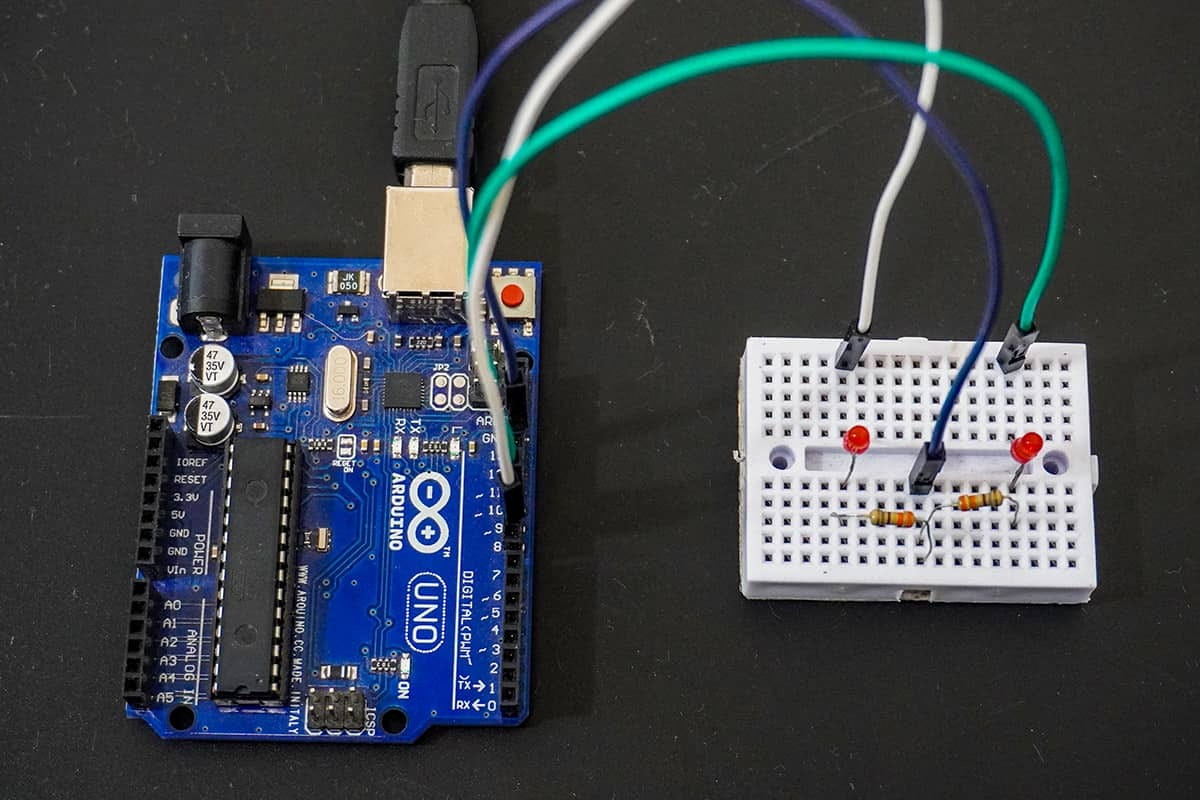
Output
Hardware setup
DSO waveform output:
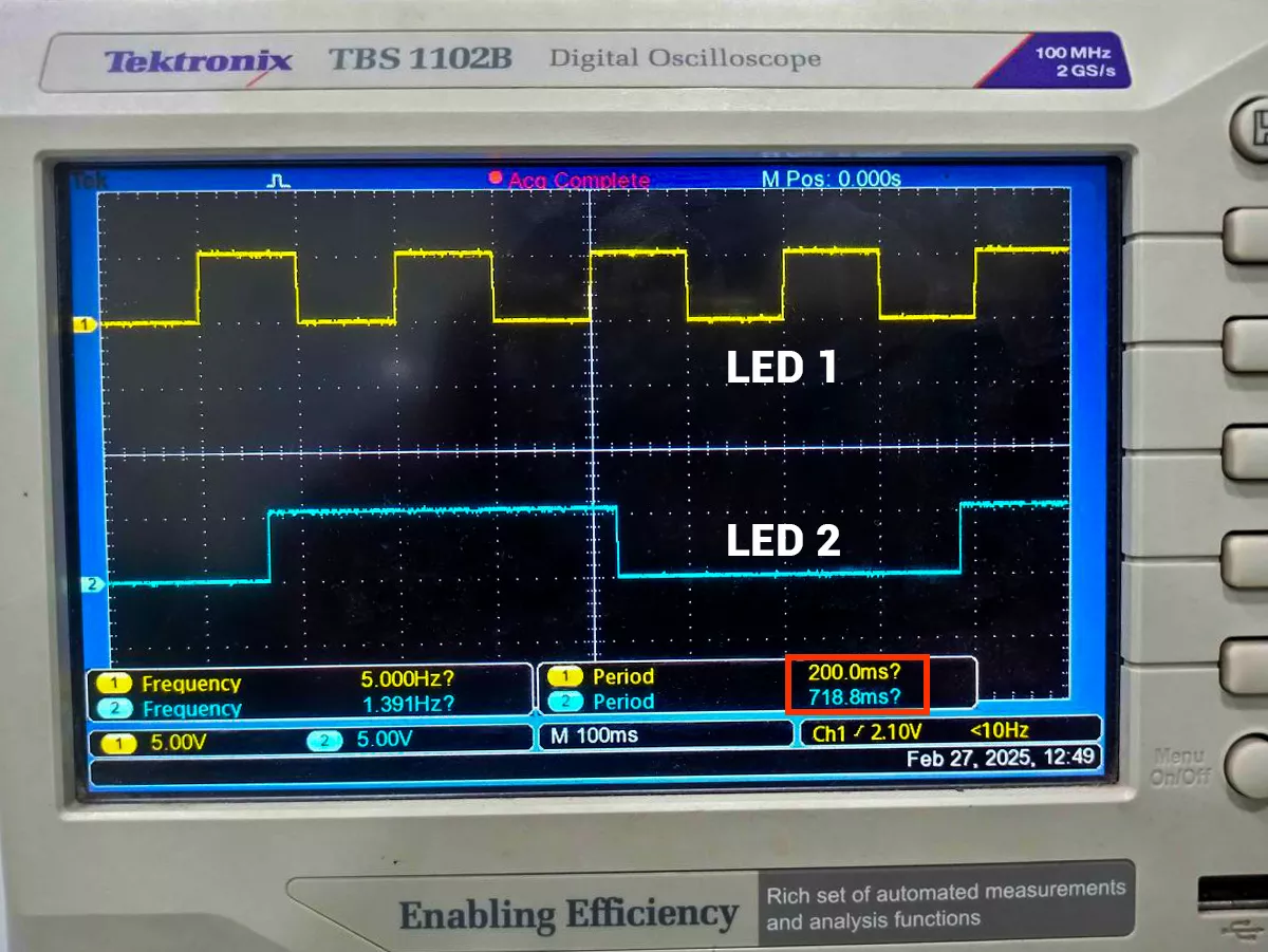
GIF Of Output
Video