31. Sine Wave Analyzer
In this task, we will analyze and calculate the Peak Voltage, RMS Voltage, and Average Voltage of a sine wave using a microcontroller.
Voltage Calculations
Peak Voltage
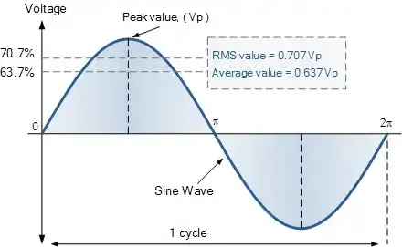
The peak voltage represents the maximum amplitude of a sine wave measured from the center line (mean value) to the peak.
Formula:
Peak_voltage = (maximum_voltage - minimum_voltage) / 2
Since the peak-to-peak voltage is twice the peak voltage:
Peak_voltage = voltage_peak_to_peak / 2
RMS Voltage
The Root Mean Square (RMS) voltage measures the effective value of an AC sine wave over time. It represents the equivalent DC voltage that would deliver the same power.
Formula:
RMS_voltage = Peak_voltage × 0.707
Real-world Application: The voltage ratings on power outlets (230V, 120V) represent RMS values. For example, a 120V RMS outlet actually has a peak voltage of approximately 170V.
Average Voltage
For a complete sine wave cycle, the true average is zero due to symmetrical oscillation above and below zero. However, for practical calculations, we consider the rectified average using only the peak voltage.
Formula:
Avg_voltage = Peak_voltage × 0.637
Sine Wave Generation Using ESP32
Why Use ESP32?
Most developers don't have access to professional signal generators. The ESP32's built-in Digital-to-Analog Converter (DAC) can serve as an effective signal generator for testing purposes.
Safety Warning
CAUTION: Ensure external sine wave signals remain within the microcontroller’s GPIO voltage range. Higher voltages will damage the microcontroller.
Code Implementation
// Define DAC pins
#define DAC_CH1 25

void setup() {
  // Nothing here!
}

void loop() {
  // Generate a Sine Wave
  // Step one degree at a time
  for (int deg = 0; deg < 360; deg = deg + 1) {
    // Calculate sine and write to DAC
    dacWrite(DAC_CH1, int(128 + 64 * sin(deg * PI / 180)));
  }
}
Code Explanation
DAC Function
dacWrite(pin, value): Outputs analog voltage from 0V to 3.3V for values ranging from 0 to 255- 0° to 90°
Sine Function Behavior
sin(deg * PI / 180): Converts degrees to radians and calculates the sine value
| Degree | Output of sin() function |
|---|---|
| 0° to 90° | 0 to 1 |
| 90° to 180° | 1to 0 |
| 180° to 270° | 0 to -1 |
| 270° to 360° | -1 to 0 |
Formula Breakdown: 128 + 64 * sin_value
- 64 (Amplitude): Controls the peak amplitude. Can be varied from 0 to 127
- Setting to 128 would result in 256, producing 0V on DAC
- For maximum amplitude, use 127: 128 + 127 * sin_value
- 128 (DC Offset): Shifts output voltage by +1.65V
- When
sin()= 0: DAC outputs 1.65V - When
sin()= -1: DAC outputs 0V - This creates a DC-shifted sine wave
- When
Circuit Setup
- DAC output (GPIO 25) → Sine-wave signal output
- Common ground between ESP32 and the measurement circuit
Now we have to analyze this generated sine wave using a microcontroller.
Implementation Approach
The measurement algorithm follows this strategy:
- Sampling Period: Analyze ADC values for 1 second
- Frequency Compatibility: Supports waveforms with frequencies as low as 1Hz
- Value Extraction: Capture the minimum and maximum voltage values
- Calculations: Compute Peak, RMS, and Average voltages using the captured values
This approach ensures accurate measurements across a wide range of sine wave frequencies while providing a practical solution for voltage analysis without expensive equipment.
Below are the solutions to the given task using different microcontrollers
- STM32
- Arduino UNO
Note: The current task requires a highly accurate ADC. However, the ESP32’s built-in ADC is non-linear and shows poor accuracy near the voltage edges (close to 0 V and Vref). Due to this limitation, we are not implementing this task using ESP32.
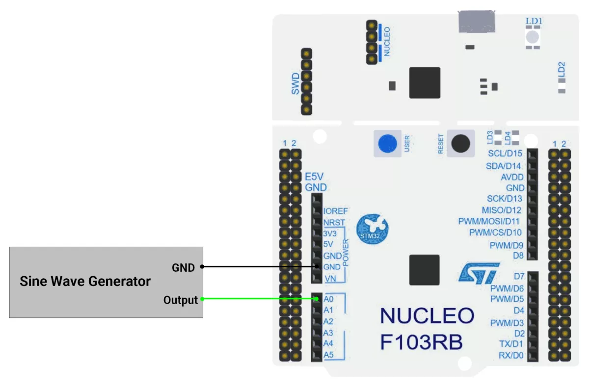
We’re using an STM32 NUCLEO-F103RB board, which runs at a 3.3V logic level.
Key Peripherals Used:
- ADC1 Channel 0 (PA0): Reads the analog voltage.
- TIM4: Basic timer to generate a timing interval.
- USART2: For serial communication with a serial terminal to display measured values.
STM32 Hardware Connection
- ADC connection:
- Connect the sine wave signal to PA0
- Make the ground common.
- Use USART2 on the STM32 board for serial communication to display the measured values on a serial terminal. This typically connects to the USB interface from the board to the PC.
- Power the STM32 board through the USB cable connected to your computer for both power and UART communication.
Circuit Diagram
STM32 Firmware Implementation
Project Setup in STM32CubeIDE
- Create a Project
- Open STM32CubeIDE, start a new project, and select the NUCLEO-F103RB board.
- Basic Configuration (via CubeMX inside CubeIDE)
- Clock: Use the default HSI oscillator with PLL enabled (as configured in
SystemClock_Config). - GPIO: Enable clocks for PORTA, PORTB, PORTC, and PORTD.
- ADC1 (Analog Input Source)
- Resolution: 12-bit (0–4095 range).
- Conversion mode: Single, software-triggered.
- Channel: ADC_CHANNEL_0 (PA0).
- Timer 4 (TIM4 – Basic Timer):
- Mode: Basic Timer with internal clock.
- Prescaler = 1000.
- Period (ARR) = 8000.
- Under NVIC Settings, enable TIM4 global interrupt.
- USART2: Enabled at 115200 baud, 8-N-1.
- Clock: Use the default HSI oscillator with PLL enabled (as configured in
- Code Generation
- CubeMX will automatically generate all the startup code, including:
HAL_Init()→ Initializes HAL and system tick.SystemClock_Config()→ Configures system clock (HSI + PLL).MX_GPIO_Init()→ Initializes GPIO ports.MX_USART2_UART_Init()→ Configures UART2.MX_ADC1_Init()→ Configures ADC1 for analog input.MX_TIM4_Init()→ Configures TIM4 as basic timer
- This code sets up the hardware and prepares the project for firmware development, so we only need to add our application logic in the user code sections
- CubeMX will automatically generate all the startup code, including:
Code Snippets from main.c
ADC Initialization (MX_ADC1_Init):
static void MX_ADC1_Init(void)
{
  ADC_ChannelConfTypeDef sConfig = {0};

  /** Common config
  */
  hadc1.Instance = ADC1;
  hadc1.Init.ScanConvMode = ADC_SCAN_DISABLE;
  hadc1.Init.ContinuousConvMode = DISABLE;
  hadc1.Init.DiscontinuousConvMode = DISABLE;
  hadc1.Init.ExternalTrigConv = ADC_SOFTWARE_START;
  hadc1.Init.DataAlign = ADC_DATAALIGN_RIGHT;
  hadc1.Init.NbrOfConversion = 1;
  if (HAL_ADC_Init(&hadc1) != HAL_OK)
  {
    Error_Handler();
  }

  /** Configure Regular Channel
  */
  sConfig.Channel = ADC_CHANNEL_0;
  sConfig.Rank = ADC_REGULAR_RANK_1;
  sConfig.SamplingTime = ADC_SAMPLETIME_13CYCLES_5;
  if (HAL_ADC_ConfigChannel(&hadc1, &sConfig) != HAL_OK)
  {
    Error_Handler();
  }

}
This configures ADC1 for single-channel operation with right-aligned 12-bit results.
UART2 Initialization (MX_USART2_UART_Init):
static void MX_USART2_UART_Init(void)
{
  huart2.Instance = USART2;
  huart2.Init.BaudRate = 115200;
  huart2.Init.WordLength = UART_WORDLENGTH_8B;
  huart2.Init.StopBits = UART_STOPBITS_1;
  huart2.Init.Parity = UART_PARITY_NONE;
  huart2.Init.Mode = UART_MODE_TX_RX;
  huart2.Init.HwFlowCtl = UART_HWCONTROL_NONE;
  huart2.Init.OverSampling = UART_OVERSAMPLING_16;
  if (HAL_UART_Init(&huart2) != HAL_OK)
  {
    Error_Handler();
  }
}
This configures USART2 for communication at a 115200 baud rate with 8 data bits, no parity, and 1 stop bit, supporting both transmit and receive.
TIM4 initialization
static void MX_TIM4_Init(void) {
  TIM_ClockConfigTypeDef sClockSourceConfig = { 0 };
  TIM_MasterConfigTypeDef sMasterConfig = { 0 };

  htim4.Instance = TIM4;
  htim4.Init.Prescaler = 1000;
  htim4.Init.CounterMode = TIM_COUNTERMODE_UP;
  htim4.Init.Period = 8000;
  htim4.Init.ClockDivision = TIM_CLOCKDIVISION_DIV1;
  htim4.Init.AutoReloadPreload = TIM_AUTORELOAD_PRELOAD_DISABLE;
  if (HAL_TIM_Base_Init(&htim4) != HAL_OK) {
    Error_Handler();
  }
  sClockSourceConfig.ClockSource = TIM_CLOCKSOURCE_INTERNAL;
  if (HAL_TIM_ConfigClockSource(&htim4, &sClockSourceConfig) != HAL_OK) {
    Error_Handler();
  }
  sMasterConfig.MasterOutputTrigger = TIM_TRGO_RESET;
  sMasterConfig.MasterSlaveMode = TIM_MASTERSLAVEMODE_DISABLE;
  if (HAL_TIMEx_MasterConfigSynchronization(&htim4, &sMasterConfig) != HAL_OK) {
    Error_Handler();
  }
}
Initializes TIM4 as an up-counting base timer with prescaler of 1000 and an auto-reload period of 8000 (1 s interval), using the internal clock source and default master/slave settings.
Header includes:
#include <stdio.h>
#include <string.h>
#include <math.h>
Private defines and variables:
#define ADC_MAX_VALUE       4095
#define ADC_REF_VOLTAGE     3.3
#define VOLTAGE_OFFSET      0.05

volatile uint8_t g_flag = 0;
char uartBuffer[80];   //Tx Buffer for UART messages
Callback Function
// Period elapsed callback
void HAL_TIM_PeriodElapsedCallback(TIM_HandleTypeDef* htim) {
  if (htim->Instance == TIM4) {
    g_flag = 1;
  }
}
This callback function sets g_flag to 1 when TIM4's period elapses
Float to String utility function
/**
  * @brief  Converts a float to a string with specified decimal places
  * @param  val: The float value to convert
  * @param  buffer: Pointer to the output buffer
  * @param  decimals: Number of decimal places to show
  * @retval None
  */
static void floatToStr(float val, char* buffer, uint8_t decimals) {
  int32_t whole = (int32_t)val;
  float fraction = val - whole;

  // Handle negative numbers
  if (val < 0) {
    fraction *= -1;
  }

  // Convert whole part
  int32_t n = whole;
  uint8_t i = 0;
  char temp[10];  // Temporary buffer for digit reversal

  if (n == 0) {
    buffer[i++] = '0';
  } else {
    if (n < 0) {
      buffer[i++] = '-';
      n = -n;
    }

    uint8_t j = 0;
    while (n > 0) {
      temp[j++] = (n % 10) + '0';
      n /= 10;
    }

    while (j > 0) {
      buffer[i++] = temp[--j];
    }
  }

  // Decimal point
  buffer[i++] = '.';

  // Fraction part
  for (uint8_t d = 0; d < decimals; d++) {
    fraction *= 10;
    uint8_t digit = (uint8_t)fraction;
    buffer[i++] = digit + '0';
    fraction -= digit;
  }

  buffer[i] = '\0';  // Null-terminate
}
Main Loop
HAL_TIM_Base_Start_IT(&htim4);  //starts TIM4 in interrupt mode
while (1) {
  uint16_t peakMaxValue = 0;              // To store the peak value
  uint16_t peakMinValue = ADC_MAX_VALUE;  // Initialize with max value to find the minimum
  uint16_t sensorValue = 0;
  uint16_t counter = 0;
  char peakVoltageStr[10];
  char rmsVoltageStr[10];
  char avgVoltageStr[10];

  g_flag = 0;
  while (g_flag == 0) ;
  g_flag = 0;

  // take a sample for 1 second
  while (g_flag == 0) {

    // Start ADC conversion
    HAL_ADC_Start(&hadc1);

    HAL_ADC_PollForConversion(&hadc1, 20);
    sensorValue = HAL_ADC_GetValue(&hadc1);

    counter++;

    // Track the peak value (highest value)
    if (sensorValue > peakMaxValue) {
      peakMaxValue = sensorValue;
    }

    // Track the minimum value (lowest point of the wave)
    if (sensorValue < peakMinValue) {
      peakMinValue = sensorValue;
    }
  }

  uint16_t peakValue = (peakMaxValue - peakMinValue) / 2;                                // peak Value calculation
  float peakVoltage = ((peakValue * ADC_REF_VOLTAGE) / ADC_MAX_VALUE) + VOLTAGE_OFFSET;  // Convert to voltage
  floatToStr(peakVoltage, peakVoltageStr, 3);

  // calculate RMS volatge
  float rmsVoltage = 0.707 * peakVoltage;  // / sqrt(2);
  floatToStr(rmsVoltage, rmsVoltageStr, 3);

  // calculate average voltage
  float avgVoltage = 0.637 * peakVoltage;
  floatToStr(avgVoltage, avgVoltageStr, 3);

  sprintf(uartBuffer,
          "Peak Voltage: %s RMS Voltage: %s Average Voltage: %s \r\n",
          peakVoltageStr, rmsVoltageStr, avgVoltageStr);

  // Send Peak, RMS, Average voltage value on UART
  HAL_UART_Transmit(&huart2, (uint8_t*)uartBuffer, strlen(uartBuffer),
                    HAL_MAX_DELAY);
}
Main Loop Workflow
- Start 1Hz Timer (TIM4) – Triggers sampling every second.
- Wait for Timer Flag (
g_flag) – Ensures synchronized 1-second sampling intervals. - Sample ADC for 1 Second:
- Continuously reads ADC values.
- Tracks max and min values to compute peak-to-peak.
- Calculate Voltages:
- Peak Voltage = (Max - Min)/2 → Converted to actual voltage.
- RMS Voltage = 0.707 × Peak (assuming sine wave).
- Average Voltage = 0.637 × Peak (full-wave rectified sine).
- Format & Transmit via UART – Sends all computed values as a string.
Expected Outcome
Every second, the serial terminal will display:
Peak Voltage: X.XXX V, RMS Voltage: Y.YYY V, Average Voltage: Z.ZZZ V
where X, Y, and Z correspond to the measured peak, RMS, and average voltages of the input sine wave.
Download Project
The complete STM32CubeIDE project (including .ioc configuration, main.c, and HAL files) is available here:
📥 Download Project
We are using the Arduino UNO development board and programming it using the Arduino IDE.
- Before uploading, make sure to select “Arduino UNO” as the board to ensure correct settings and compatibility.
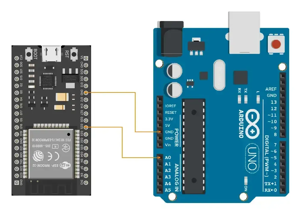
Let’s do the hardware connection.
Connect the sinewave generator to pin A0 and make the ground common.
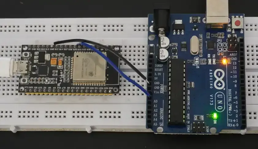
Here, we will use the ESP32 as a sine wave generator.
The circuit we will use is :
- (ESP32) pin 25 → (Arduino) pin A0
- Common ground.
Arduino UNO Circuit Connection
Arduino UNO Firmware Implementation
The approach to the code will be as follows :
- We will analyze the ADC value for 1 second to get the min and peak values.
- It will help us to calculate the values for a waveform with a frequency as low as 1Hz
- Based on the peak value and min value, we will calculate the rest of the values.
Code
#define ANALOG_PIN A0
void setup() {
  Serial.begin(9600);
}

void loop() {
  int peakValue = 0;    // To store the peak value
  int minValue = 1023;  // Initialize with max value to find the minimum

  unsigned long sampling_start_time= millis();

  // take sample for 1 second
  while(millis() - sampling_start_time < 1000){
    int sensorValue = analogRead(ANALOG_PIN);  // Read the analog value

    // Track the peak value (highest value)
    if (sensorValue > peakValue) {
      peakValue = sensorValue;
    }

    // Track the minimum value (lowest point of the wave)
    if (sensorValue < minValue) {
      minValue = sensorValue;
    }
  }

  double peakVoltage = (peakValue - minValue) / 2.0; // peak Value calculation
  peakVoltage = (peakVoltage / 1023.0) * 5.0;  // Convert to voltage

  // calculate RMS volatge
  double rmsVoltage = peakVoltage / sqrt(2);

  // calculate average voltage
  double avgVoltage = 0.637 * peakVoltage;

  // Print the results on the Serial Monitor
  Serial.print("Peak Voltage: ");
  Serial.print(peakVoltage, 3);

  Serial.print("\tRMS Voltage: ");
  Serial.print(rmsVoltage, 3);

  Serial.print("\tAverage Voltage: ");
  Serial.println(avgVoltage, 3);

  delay(100);
}
Code explanation
We need to collect the samples of a waveform over 1 second.
millis()-sampling_start_time < SAMPLING_DURATION: read and compare samples for 1 second.peakValue, minValue: The maximum value and minimum value that has occurred in 1 second are stored in these variables.peakVoltage = (peakValue - minValue) / 2.0: This formula calculatespeak_voltage, but it's in analog value, i.e., in the 0 - 1024 range.peakVoltage = (peakVoltage / 1023.0) * 5.0: here the peak voltage gets converted from analog_value to actual Voltage.rmsVoltage = peakVoltage / sqrt(2): This formula calculates RMS voltage value using peak_voltage.avgVoltage = 0.637 * peakVoltage: This formula calculates the average voltage value.
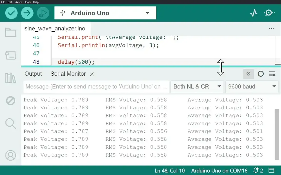
Output
The Output sine waveform from the ESP32 is given below
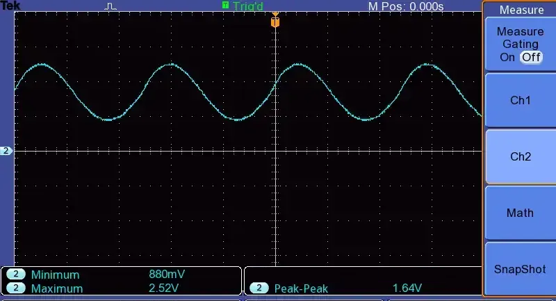
Sinewave Analyzer Hardware Setup
The output of Vpeak detected by Arduino and printed on the serial monitor is as follows