9. Single Double Click and Long Press Detection
Understanding and Interfacing a Push Button Switch
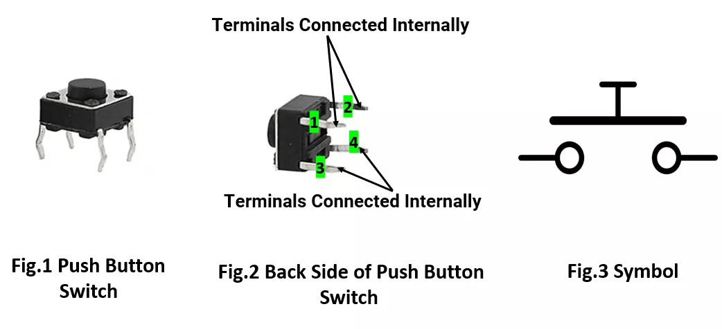
A standard push button has four pins, where pins 1–2 are internally connected, and pins 3–4 are also connected. When the button is pressed, all pins become connected (closed circuit).
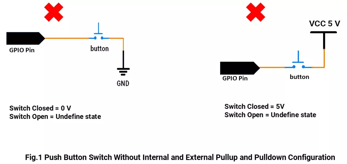
Important: Avoid Floating GPIO Pins
If the switch is not pressed and there's no pull-up or pull-down resistor, the input pin may "float," giving random HIGH/LOW readings.
Use a pull-up or pull-down resistor to keep the pin at a known voltage when idle.
Switch Interfacing Without Pull-up/ Pull-down Resistor:
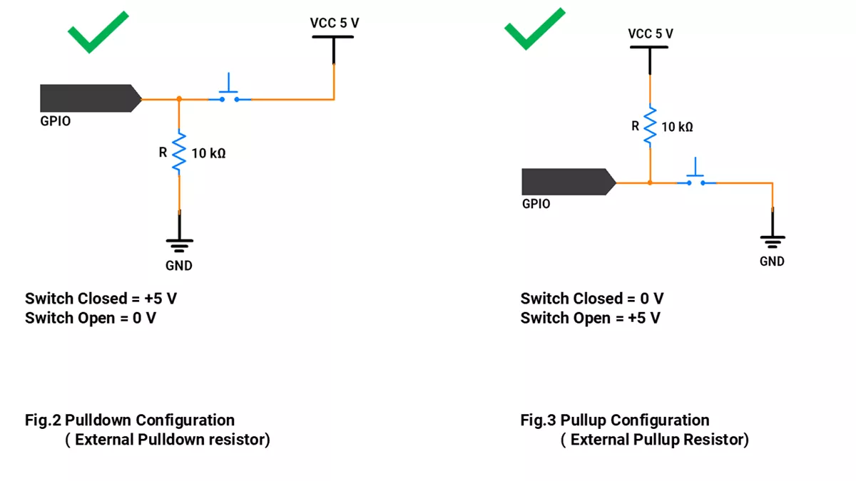
Switch Interfacing With Pull-up/ Pull-down Resistor:
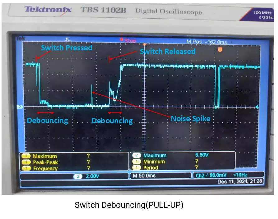
Debouncing
- When detecting single-clicks, double-clicks, or long-presses, two key factors must be considered: timing and debouncing.
- Debouncing refers to the suppression of rapid on/off fluctuations caused by the mechanical contacts inside a push button. These fluctuations, known as bounces, can lead to false triggers or multiple detections for a single press.
- To ensure reliable button detection, debouncing must be handled—either through hardware filters (like RC circuits) or software techniques (such as delay-based or state-based logic).
Detecting Press Types
We can classify button presses using timing:
- Single Click: One short press.
- Double Click: Two clicks within 400 ms.
- Long Press: Button held for more than 1 second.
So by selecting the correct switch-interfacing configurations and click timings, we can implement the given task.
Below are the solutions to the given task using different microcontrollers
- STM32
- ESP32
- Arduino UNO
We’re using an STM32 NUCLEO-F103RB board, which runs at a 3.3V logic level.
Key Peripherals Used:
- GPIO: To connect a push-button switch
- UART2: To show the press detection message on the serial terminal.
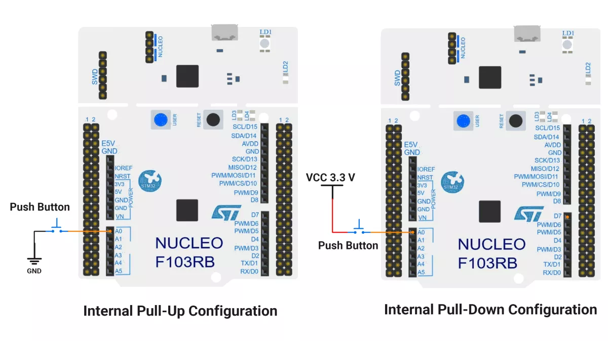
STM32 Hardware Connection
- Pull-Up Configuration: Connect one side of the button to PA0 (A0) and the other to GND. Enable the internal pull-up resistor in the program.
- Pull-Down Configuration: Connect one side of the button to PA0 (A0) and the other to VCC. Enable the internal pull-down resistor in the program.
- Connect the board to your PC via USB. This allows serial output to monitor the button press actions.
Circuit Diagram
STM32 Firmware Implementation
Project Setup in STM32CubeIDE:
- Create a Project
- Open STM32CubeIDE and start a new project, select the NUCLEO-F103RB board.
- Basic Configuration (via CubeMX inside CubeIDE)
- Clock: Keep the default internal oscillator (no custom changes needed).
- GPIO: Set PA0 (A0 pin) as
- Method 1: GPIO Input with a Pull-Up
- Method 2: GPIO Input with a Pull-Down
- UART (for Serial Print):
- Enable USART2 (this is already connected to the ST-LINK USB port on the Nucleo).
- TX = PA2, RX = PA3
- Baud Rate = 115200, Data = 8 bits, Parity = None, Stop = 1, Flow Control = None.
- Code Generation
- CubeMX will automatically generate all the startup code, including:
HAL_Init()→ Initializes the HAL library.SystemClock_Config()→ Configures system clock.MX_USART2_UART_Init()→ Sets up USART2.MX_GPIO_Init()→ Configures GPIO (e.g., PA0).
- This code sets up the hardware and prepares the project for firmware development, so we only need to add our application logic in the user code sections.
- CubeMX will automatically generate all the startup code, including:
Code Snippets from main.c
GPIO Initialization
// In MX_GPIO_Init()
GPIO_InitStruct.Pin = GPIO_PIN_0;
GPIO_InitStruct.Mode = GPIO_MODE_INPUT;
GPIO_InitStruct.Pull = GPIO_PULLUP;  // or GPIO_PULLDOWN as needed
HAL_GPIO_Init(GPIOA, &GPIO_InitStruct);
This configures pin PA0 as a digital input with an internal pull-up resistor enabled. The pull-up resistor ensures the input reads HIGH when the button is not pressed, preventing a floating input.
UART Initialization
huart2.Instance = USART2;
huart2.Init.BaudRate = 115200;
huart2.Init.WordLength = UART_WORDLENGTH_8B;
huart2.Init.StopBits = UART_STOPBITS_1;
huart2.Init.Parity = UART_PARITY_NONE;
huart2.Init.Mode = UART_MODE_TX_RX;
huart2.Init.HwFlowCtl = UART_HWCONTROL_NONE;
huart2.Init.OverSampling = UART_OVERSAMPLING_16;
if (HAL_UART_Init(&huart2) != HAL_OK) {
    Error_Handler();
}
This sets up USART2 peripheral for serial communication with these parameters: 115200 baud rate, 8 data bits, 1 stop bit, no parity, transmit and receive enabled, and no hardware flow control. This streamlines sending messages to a serial terminal.
Header File Include
#include <string.h>
Includes standard C string functions, used here mainly for strlen() to determine string lengths when sending UART messages.
Macros for Port and Pin
#define SWITCH_PORT GPIOA
#define SWITCH_PIN  GPIO_PIN_0
Defines easier-to-read names for the button's GPIO port and pin. Improves code readability and maintainability.
Variables for Debounce and Button State
uint8_t g_debounceDuration = 50;   // debounce time in milliseconds
uint8_t g_previousButtonState = 1; // last read input state (1 = button not pressed)
uint8_t g_currentButtonState = 1;  // current stable button state
uint32_t g_lastDebounceTime = 0;   // timestamp of last state change
uint32_t g_pressStartTime;          // time when button press began
uint32_t g_releaseTime;             // time when button released
These variables help implement a debounce mechanism to filter out noisy transitions of the mechanical switch and reliably detect button press and release events.
Serial Print
void printOnSerialMonitor(char *msg) {
    HAL_UART_Transmit(&huart2, (uint8_t*) msg, strlen(msg), HAL_MAX_DELAY);
}
Sends a null-terminated string msg over UART to the connected PC terminal synchronously. Useful for reporting button events in real time.
Debounced Button Press Check
uint8_t debouncedButtonPressCheck(GPIO_TypeDef *GPIOx, uint16_t GPIO_Pin, uint8_t expectedState) {
    uint8_t buttonReading = HAL_GPIO_ReadPin(GPIOx, GPIO_Pin);
    // If the button state has changed, reset the debounce timer
    if (buttonReading != g_previousButtonState) {
        g_lastDebounceTime = HAL_GetTick();
    }
    g_previousButtonState = buttonReading;
    // Only accept the state if it has remained stable longer than debounce time
    if ((HAL_GetTick() - g_lastDebounceTime) > g_debounceDuration) {
        if (buttonReading != g_currentButtonState) {
            g_currentButtonState = buttonReading;
            if (g_currentButtonState == expectedState) {
                return 1; // Valid state detected
            }
        }
    }
    return 0; // No valid debounced press detected
}
Reads the button pin and uses a time delay to ensure the reading is stable (debounced). Returns 1 if a valid transition matching expectedState (0 for pressed with pull-up config) occurs; otherwise returns 0.
Main Firmware Logic with Explanation
Method 1 – Internal pull-up Configuration
int main(void) {
    HAL_Init();                    // Initialize the HAL library and system peripherals
    SystemClock_Config();          // Configure system clock (default internal oscillator)
    MX_GPIO_Init();                // Initialize GPIO pins (button, LED if configured)
    MX_USART2_UART_Init();         // Initialize UART communication

    printOnSerialMonitor("Start \r\n"); // Inform that program started

    while (1) {
        // Check for button press (assuming pull-up logic: pressed = 0)
        if (debouncedButtonPressCheck(SWITCH_PORT, SWITCH_PIN, 0)) {
            g_pressStartTime = HAL_GetTick();    // Record time when button is pressed

            // Wait until button is released (goes back to 1 = HIGH)
            while (!debouncedButtonPressCheck(SWITCH_PORT, SWITCH_PIN, 1));

            g_releaseTime = HAL_GetTick();       // Record time when button is released

            // Determine press duration to differentiate long press vs click
            if ((g_releaseTime - g_pressStartTime) > 1000) {
                printOnSerialMonitor("Long press detected.\r\n");  // Press > 1 second
            } else {
                // Check for a double click within a 400ms timeout
                while (1) {
                    if (debouncedButtonPressCheck(SWITCH_PORT, SWITCH_PIN, 0)) {
                        printOnSerialMonitor("Double click detected.\r\n");
                        break;
                    }
                    if ((HAL_GetTick() - g_releaseTime) > 400) {
                        printOnSerialMonitor("Single click detected.\r\n");
                        break;
                    }
                }
            }
        }
    }
}
Initialization: HAL, system clock, GPIO, and UART are set up. A startup message is printed on the serial monitor.
Button Monitoring: The program continuously checks for button presses with debounce handling.
Press Handling:
- On press, it records the press start time.
- On release, it records the release time.
- If press duration > 1s → Long Press.
- Else → Short Press:
- Waits 400ms for another press.
- If detected → Double Click.
- If not → Single Click.
Method 2 – Internal pull-down Configuration
This method is similar to the internal pull-up approach, with the main difference being the button logic handled inside the while(1) loop of the main function.
Also, configure the GPIO pin as input with Pull-Down.
Replace the existing code block:
while (1) {
    // Check for button press (pull-up logic: pressed = 0)
    if (debouncedButtonPressCheck(SWITCH_PORT, SWITCH_PIN, 0)) {
        g_pressStartTime = HAL_GetTick();    // Record time when button is pressed

        // Wait until button is released (goes back to 1 = HIGH)
        while (!debouncedButtonPressCheck(SWITCH_PORT, SWITCH_PIN, 1));

        ...
    }
  }
with the following:
while (1) {
    // Check for button press (pull-down logic: pressed = 1)
    if (debouncedButtonPressCheck(SWITCH_PORT, SWITCH_PIN, 1)) {
        g_pressStartTime = HAL_GetTick();    // Record time when button is pressed

        // Wait until button is released (goes back to 0 = LOW)
        while (!debouncedButtonPressCheck(SWITCH_PORT, SWITCH_PIN, 0));

        ...
    }
}
Key Difference
- Pull-Up Mode: Pressed = 0, Released = 1
- Pull-Down Mode: Pressed = 1, Released = 0
Download Project
The complete STM32CubeIDE project (including .ioc configuration, main.c, and HAL files) is available here:
📥Download Project
We are using the ESP32 DevKit v4 development board and programming it using the Arduino IDE.
- Before uploading, make sure to select “ESP32 Dev Module” as the board to ensure correct settings and compatibility.
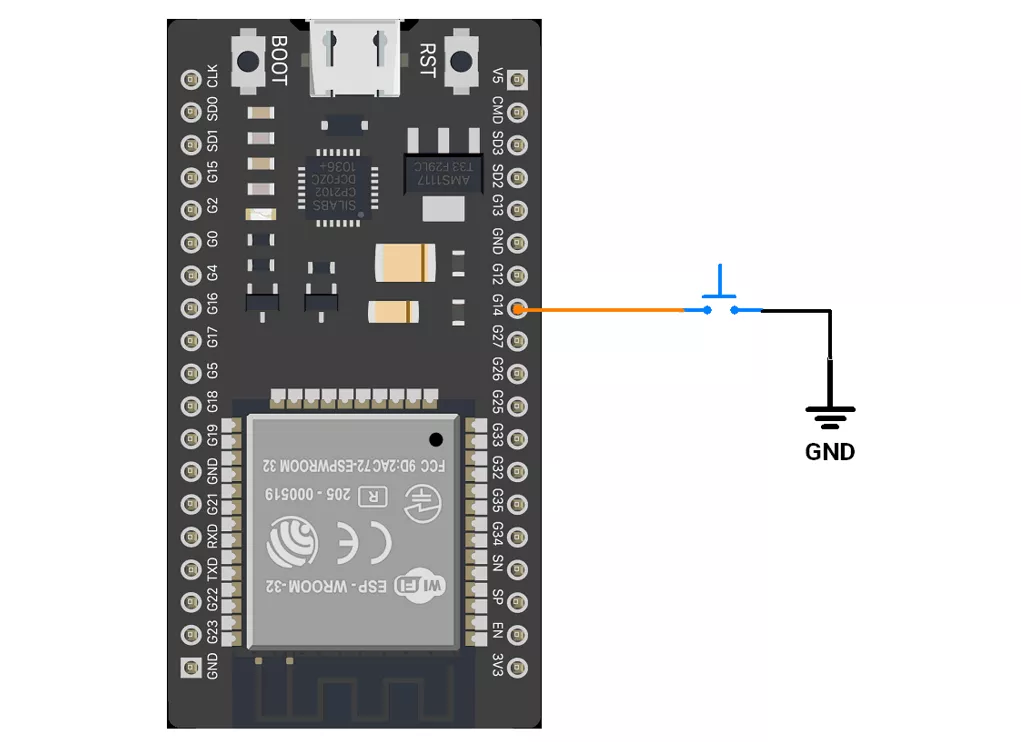
We are interfacing a push-button with the ESP32.
Note: Avoid using GPIOs 34–39 for push-buttons while using ESP32 because they do not support pull-up/down resistors internally.
Method 1 – Pull-up Configuration
ESP32 Circuit Connection
- GPIO 14 – Used to connect the push-button to the input pin.
- Push Button, one terminal is connected to GPIO 14.
- The other terminal is connected to GND.
- Internal pull-up is enabled in the program.
ESP32 Firmware Implementation
Code for Method 1 (Internal Pull-up):
#define BUTTON_PIN 14  // Pin connected to the button
#define LONG_PRESS_TIME 1000
#define SINGLE_PRESS_TIME 400


uint8_t debounce_duration = 50;        // Minimum time to debounce button (in milliseconds)
uint8_t previous_button_state = HIGH;  // Previous state of the button
uint8_t current_button_state = HIGH;   // Current state of the button
unsigned long last_debounce_time = 0;  // Time when button state last changed
unsigned long press_start_time;        // Time when button press starts
unsigned long release_time;            // Duration of the button press

void setup() {
  pinMode(BUTTON_PIN, INPUT_PULLUP);  // Configure button pin with internal pull-up resistor
  Serial.begin(115200);
}

void loop() {

  if (debounced_button_press_check(BUTTON_PIN, LOW)) {
    press_start_time = millis();  // Record the time the button was pressed
    while (!debounced_button_press_check(BUTTON_PIN, HIGH))
      ;
    release_time = millis() - press_start_time;  // Calculate the button release duration

    if (release_time > LONG_PRESS_TIME) {
      Serial.println("Long press detected");
    } else {
      // Check for single or double press within a specific time frame
      while (1) {

        if (debounced_button_press_check(BUTTON_PIN, LOW)) {
          Serial.println("Double click detected");
          break;
        }
        if ((millis() - press_start_time) > SINGLE_PRESS_TIME) {
          Serial.println("Single click detected");
          break;
        }
      }
    }
  }
}

//Checks for a debounced button press and returns true if detected, false otherwise.
bool debounced_button_press_check(uint8_t pin, bool expected_state) {
  bool button_reading = digitalRead(pin);

  // If the button state has changed, reset the debounce timer
  if (button_reading != previous_button_state) {
    last_debounce_time = millis();
  }
  previous_button_state = button_reading;

  // If the state has remained stable beyond the debounce duration, consider it valid
  if ((millis() - last_debounce_time) > debounce_duration) {
    if (button_reading != current_button_state) {
      current_button_state = button_reading;
      if (current_button_state == expected_state) {
        return true;  // Return true if the desired state is detected
      }
    }
  }
  return false;  // Return false if no valid press is detected
}
Code Explanation
pinMode(BUTTON_PIN, INPUT_PULLUP);– Configures GPIO 14 as input with internal pull-up resistor enabled.debounced_button_press_check()– Ensures the button press is stable for at least 50 ms before accepting it as valid.- When a press is detected, store the press start time.
- Wait for the release and calculate the press duration.
If press > 1,000 ms→ Long Press.- If shorter, wait for a possible second press within 400 ms:
- If detected → Double Click.
- If not → Single Click.
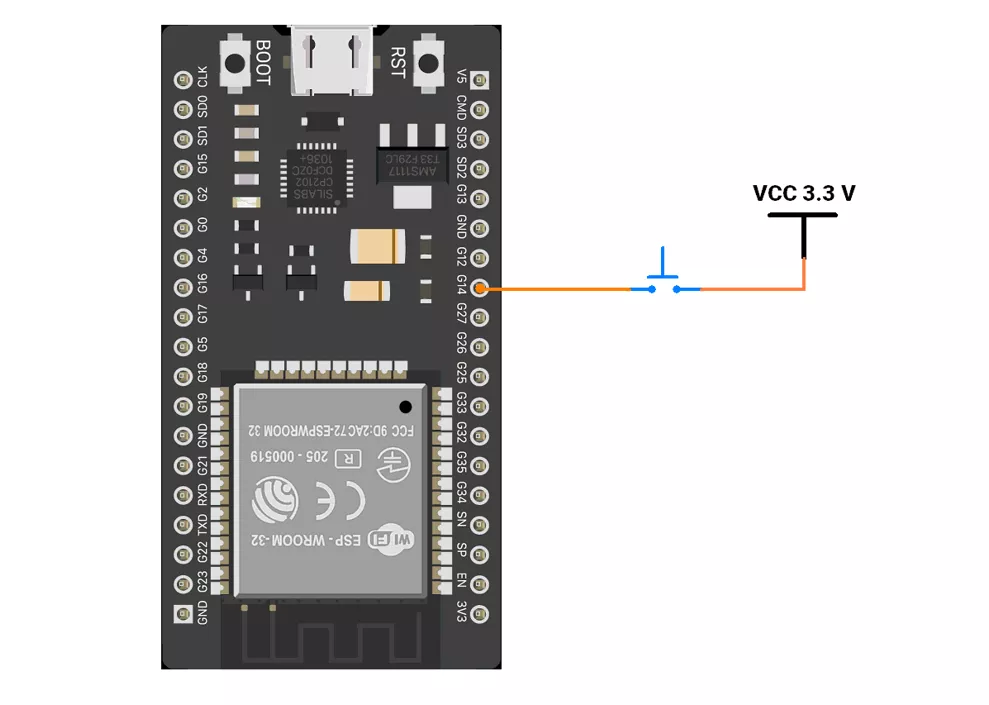
Method 2 – Pull-down Configuration
In method 2, a pull-down resistor keeps the GPIO pin at LOW (0 V) when the button is not pressed, avoiding floating values.
When the button is pressed, the pin is driven HIGH (3.3 V), so the input reads as HIGH (inverse of method 1).
ESP32 Circuit Connection
- GPIO 14 – Used to connect the push button switch.
- Push Button, one terminal is connected to GPIO 14.
- The other terminal is connected to VCC (3.3V).
- Internal pull-down is enabled in the program.
ESP32 Firmware Implementation
Code for Method 2 (Internal Pull-down)
This method is similar to the internal pull-up approach, with the main difference being the button logic handled inside the setup() and loop() functions.
Also, configure the GPIO pin as input with Pull-Down.
Replace the existing code statements :
setup()
pinMode(BUTTON_PIN, INPUT_PULLUP);
loop()
-
if (debounced_button_press_check(BUTTON_PIN, LOW)) while (!debounced_button_press_check(BUTTON_PIN, HIGH)) ;
With the following:
setup()
pinMode(BUTTON_PIN, INPUT_PULLDOWN);
loop()
-
if (debounced_button_press_check(BUTTON_PIN, HIGH)) while (!debounced_button_press_check(BUTTON_PIN, LOW)) ;
We are using the Arduino UNO development board and programming it using the Arduino IDE.
- Before uploading, make sure to select “Arduino UNO” as the board to ensure correct settings and compatibility.
We are interfacing a push-button with the Arduino UNO.
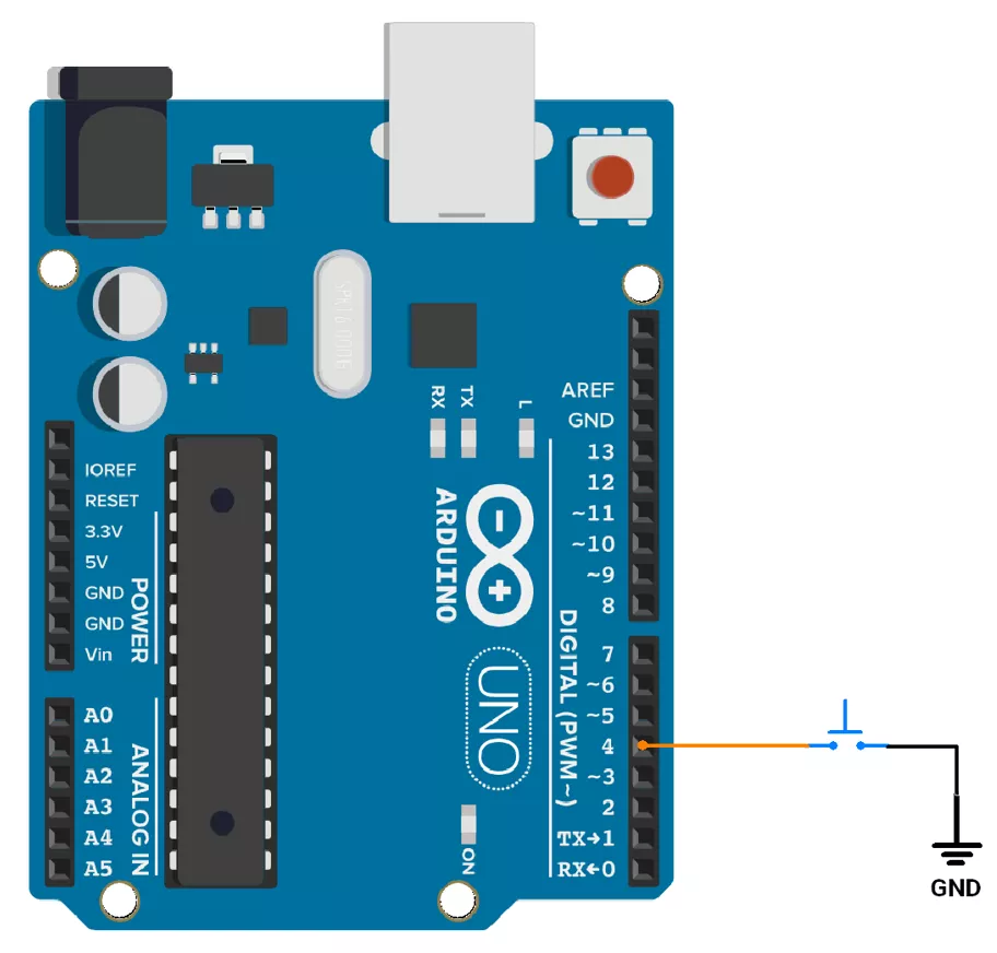
Method 1: PULLUP Configuration
- So let’s connect the push-button switch using a pull-up configuration. We will connect the switch to digital pin 4 of the Arduino UNO. It has an internal pull-up resistor, so we will use it for the Switch interfacing.
Arduino UNO Circuit Connection
Arduino UNO Firmware Implementation
Code
const int button_pin = 4;  // Pin connected to the button

unsigned long debounce_duration = 50;  // Minimum time to debounce button (in milliseconds)
int previous_button_state = HIGH;      // Previous state of the button
int current_button_state = HIGH;       // Current state of the button
unsigned long last_debounce_time = 0;  // Time when button state last changed
unsigned long press_start_time;        // Time when button press starts
unsigned long release_time;            // Duration of the button press

void setup() {
  pinMode(button_pin, INPUT_PULLUP);  // Configure button pin with internal pull-up resistor
  Serial.begin(115200);
}

void loop() {

  if (debounced_button_press_check(button_pin, LOW)) {
    press_start_time = millis();  // Record the time the button was pressed
    while (!debounced_button_press_check(button_pin, HIGH))
      ;
    release_time = millis() - press_start_time;  // Calculate the button release duration

    if (release_time > 1000) {
      Serial.println("Long press detected");
    } else {
      // Check for single or double press within a specific time frame
      while (1) {
        if (debounced_button_press_check(button_pin, LOW)) {
          Serial.println("Double click detected");
          break;
        }
        if ((millis() - press_start_time) > 400) {
          Serial.println("Single click detected");
          break;
        }
      }
    }
  }
}

//Checks for a debounced button press and returns true if detected, false otherwise.
bool debounced_button_press_check(int pin, bool expected_state) {
  int button_reading = digitalRead(pin);

  // If the button state has changed, reset the debounce timer
  if (button_reading != previous_button_state) {
    last_debounce_time = millis();
  }
  previous_button_state = button_reading;

  // If the state has remained stable beyond the debounce duration, consider it valid
  if ((millis() - last_debounce_time) > debounce_duration) {
    if (button_reading != current_button_state) {
      current_button_state = button_reading;
      if (current_button_state == expected_state) {
        return true;  // Return true if the desired state is detected
      }
    }
  }
  return false;  // Return false if no valid press is detected
}
Code Explanation
- The button is connected to pin 4 with an internal pull-up resistor.
debounced_button_press_check()detects a button press by filtering for debouncing and returns true if the button state is stable and matches the expected state for the debounce duration; else, it returns false.- If pressed, it measures how long the button is held:
- Long press (> 1 sec): Prints "Long press detected."
- Single click or double click: If the consecutive two-click press happens within 400ms, we will detect it as a double click. (irrespective of second click press time) and printed it as “double click”; otherwise, prints "Single click detected."
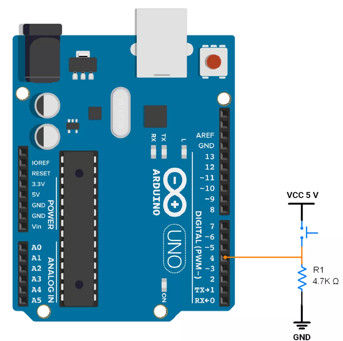
Method 2: PULLDOWN Configuration
- So let’s connect the push-button switch using a pull-down configuration. We will connect the switch to digital pin 4 of the Arduino UNO.
- As Arduino UNO does not have an internal pull-down resistor so we have to use an external pull-down resistor.
- The pull-down resistor is typically between 4.7kΩ and 10kΩ, so we will use a 4.7kΩ resistor.
Arduino UNO Circuit Connection
Arduino UNO Firmware Implementation
Code
This method is similar to the internal pull-up approach, with the main difference being the button logic handled inside the loop() function.
Also, configure the GPIO pin as input.
Replace the existing code statements :
setup()
pinMode(BUTTON_PIN, INPUT_PULLUP);
loop()
if (debounced_button_press_check(BUTTON_PIN, LOW))while (!debounced_button_press_check(BUTTON_PIN, HIGH)) ;
With the following:
setup()
-
pinMode(BUTTON_PIN, INPUT);
loop()
if (debounced_button_press_check(BUTTON_PIN, HIGH))while (!debounced_button_press_check(BUTTON_PIN, LOW)) ;
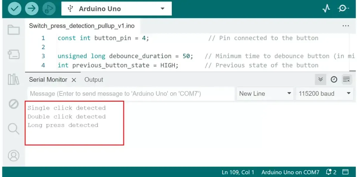
OUTPUT
Switch the interfacing hardware connection (Using internal pullup).
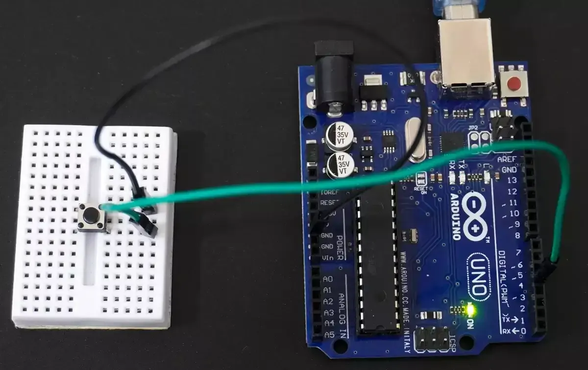
Single click, double click, and long press printed on serial monitor.