73. Sleep Mode with Button Press Wake-Up
Objective
We have to build a low-power system that minimizes energy consumption by using the microcontroller’s power-saving features. The system must remain in power-saving mode until triggered by a user input (push button), at which point it wakes up, performs an ADC measurement, transmits the result, and returns to low-power mode.
Functional Requirements
- Low-Power Operation
- The microcontroller operates in a designated power-saving mode to reduce power draw when idle.
- Core clock and peripheral clocks are suspended as per the selected power saving mode configuration.
- Wake-Up Trigger
- Push button connected to a dedicated external interrupt pin (e.g., EXTI on STM32, INTx on AVR, GPIO interrupt on ESP32).
- A falling-edge or rising-edge interrupt detection is used to minimize false triggers due to switch bounce (debounce handled in software).
- ADC Measurement
- Upon wake-up, the system reads the ADC value from a potentiometer connected to an analog input pin.
- ADC resolution is configured according to the MCU’s capability (e.g., 10-bit for AVR, 12-bit for STM32).
- Sampling time is optimized for both accuracy and speed.
- Data Transmission
- The ADC reading is transmitted via a serial interface (e.g., UART to PuTTY, Arduino Serial Monitor).
- Baud rate and framing parameters are preconfigured to ensure compatibility with the terminal software.
- Return to Sleep
- After ADC reading and data transmission, the system automatically re-enters low-power mode without additional user intervention.
High-Level Workflow
- System Initialization
- Configure GPIOs for push button (input with interrupt) and potentiometer (analog input).
- Initialize ADC and UART peripherals.
- Enable global interrupts.
- Enter Low-Power Mode
- MCU enters sleep/stop mode awaiting interrupt from push button.
- Wake-Up Event
- Button press generates an external interrupt signal.
- MCU resumes operation from the interrupt handler.
- Read and Transmit ADC Value
- Perform ADC conversion on the potentiometer input.
- Format and send the ADC value to the serial terminal.
- Re-Enter Low-Power Mode
- Resume power saving mode immediately after transmission.
Key Implementation Notes
- Debounce Handling:
Software-based delay or state-check mechanism to avoid multiple false wake-ups from mechanical switch bounce. - Interrupt Configuration:
External interrupt set to edge-sensitive mode for optimal wake-up latency. - Power Mode Selection:
- STM32: STOP or STANDBY mode with EXTI wake-up.
- AVR: POWER-DOWN mode with INT0/INT1 wake-up.
- ESP32: Deep Sleep mode with GPIO wake-up.
- Peripheral Wake-Up:
Ensure ADC and UART clocks are re-enabled after wake-up before measurement and transmission.
So, by considering the above points, we can implement the task.
Below are the solutions to the given task using different microcontrollers
- STM32
- ESP32
- Arduino UNO
We’re using an STM32 NUCLEO-F103RB board.
Key Peripherals Used:
- ADC1: Reads the analog voltage from the potentiometer.
- USART2: For serial communication to display ADC values on the serial terminal.
- GPIO PA8 (D7): User button input
STM32 Low-Power Modes Overview
The STM32F103RB (Cortex-M3) supports three low-power modes. Choosing the right mode depends on the required wake-up latency and system current budget.
- Sleep Mode
- CPU stopped, peripherals continue running.
- Wake-up source: Any interrupt/event.
- Lowest wake-up latency (few cycles).
- Suitable for short idle periods when peripherals must stay active.
- Stop Mode
- CPU, PLL, and most peripherals stopped; SRAM and register contents retained.
- Internal voltage regulator in low-power mode.
- Wake-up source: EXTI line (e.g., push button), RTC, USB, or other interrupts.
- Balance between low power and fast wake-up.
- Chosen for this project because ADC/UART can be re-enabled after wake-up.
- Standby Mode
- The lowest power mode: VCORE powered off, SRAM and registers lost, only backup domain retained.
- Wake-up source: Dedicated pins (WKUP), RTC alarm, reset.
- Requires full reinitialization after wake-up.
- Not suitable here since we need to retain ADC and UART context.
In this task, STOP Mode is preferred because it saves significant power while still allowing wake-up on button press via EXTI (PA8). After waking, we reconfigure clocks and peripherals before ADC and UART operations.
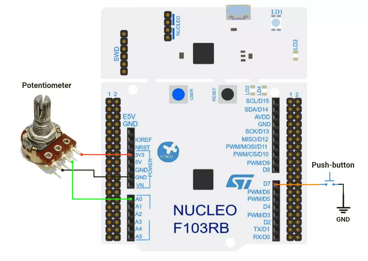
STM32 Hardware Connections
- Button: Connect one terminal to PA8 and the other to GND (internal pull-up enabled).
- Potentiometer: Connect the middle terminal to PA0 (ADC1_IN0), outer terminals to 3.3V and GND.
- UART: USART2 (TX: PA2, RX: PA3) is connected via the ST-Link virtual COM port.
Circuit Diagram
STM32 Firmware Implementation
Project Setup in STM32CubeIDE
- Create a Project
- Open STM32CubeIDE and start a new project, select the NUCLEO-F103RB board.
- Basic Configuration (via CubeMX inside CubeIDE)
- Clock: Keep the default internal oscillator (no custom changes needed).
- GPIO: Set PA8 (D7 pin) as a GPIO Input with a Pull-Up configuration.
- UART (for Serial Print):
- Enable USART2 (this is already connected to the ST-LINK USB port on the Nucleo).
- TX = PA2, RX = PA3
- Baud Rate = 115200, Data = 8 bits, Parity = None, Stop = 1, Flow Control = None.
- ADC Configurations
- Navigate to the Pinout & Configuration tab
- Select the PA0 pin and configure it as ADC1_IN0 for analog input
- Under the Analog section, expand ADC1 and enable IN0 channel
- Set ADC parameters: Resolution to 12 bits, Data Alignment to Right aligned
- Code Generation
- CubeMX will automatically generate all the startup code, including:
HAL_Init()→ Initializes the HAL library.SystemClock_Config()→ Configures system clock.MX_USART2_UART_Init()→ Sets up USART2.MX_GPIO_Init()→ Configures GPIO (e.g., PA8).MX_ADC1_Init()→ Configures ADC1_IN0 (e.g., PA0).
- This code sets up the hardware and prepares the project for firmware development, so we only need to add our application logic in the user code sections
- CubeMX will automatically generate all the startup code, including:
Code Snippets from main.c
GPIO Initialization (Button Config on PA8)
Configures PA8 as an external interrupt input activated on falling edge (button press). Pull-up resistor ensures a stable idle high level.
static void MX_GPIO_Init(void) {
  GPIO_InitTypeDef GPIO_InitStruct = { 0 };
  /* USER CODE BEGIN MX_GPIO_Init_1 */

  /* USER CODE END MX_GPIO_Init_1 */

  /* GPIO Ports Clock Enable */
  __HAL_RCC_GPIOC_CLK_ENABLE();
  __HAL_RCC_GPIOD_CLK_ENABLE();
  __HAL_RCC_GPIOA_CLK_ENABLE();
  __HAL_RCC_GPIOB_CLK_ENABLE();

  /*Configure GPIO pin : PA8 */
  GPIO_InitStruct.Pin = GPIO_PIN_8;
  GPIO_InitStruct.Mode = GPIO_MODE_IT_FALLING;
  GPIO_InitStruct.Pull = GPIO_PULLUP;
  HAL_GPIO_Init(GPIOA, &GPIO_InitStruct);

  /* USER CODE BEGIN MX_GPIO_Init_2 */

  /* Set EXTI IRQ for PA8 (EXTI8 → EXTI9_5_IRQn) */
  HAL_NVIC_SetPriority(EXTI9_5_IRQn, 0, 0);  // High priority (0 = highest)
  HAL_NVIC_EnableIRQ(EXTI9_5_IRQn);

  /* USER CODE END MX_GPIO_Init_2 */
}- Purpose: Detects button press and triggers EXTI interrupt for waking the MCU and processing logic.
UART Initialization
Configures UART2 for reliable communication via a serial terminal. Settings are: 115200 baud, 8/N/1, no flow control.
huart2.Instance = USART2;
huart2.Init.BaudRate = 115200;
huart2.Init.WordLength = UART_WORDLENGTH_8B;
huart2.Init.StopBits = UART_STOPBITS_1;
huart2.Init.Parity = UART_PARITY_NONE;
huart2.Init.Mode = UART_MODE_TX_RX;
huart2.Init.HwFlowCtl = UART_HWCONTROL_NONE;
huart2.Init.OverSampling = UART_OVERSAMPLING_16;
HAL_UART_Init(&huart2);- Purpose: Enables UART logging of ADC results to a serial monitor.
ADC Initialization
Configures ADC1 to perform a single conversion on channel 0, right-aligned result, triggered by software.
hadc1.Instance = ADC1;
hadc1.Init.ScanConvMode = ADC_SCAN_DISABLE;
hadc1.Init.ContinuousConvMode = DISABLE;
hadc1.Init.DiscontinuousConvMode = DISABLE;
hadc1.Init.ExternalTrigConv = ADC_SOFTWARE_START;
hadc1.Init.DataAlign = ADC_DATAALIGN_RIGHT;
hadc1.Init.NbrOfConversion = 1;
HAL_ADC_Init(&hadc1);
sConfig.Channel = ADC_CHANNEL_0;
sConfig.Rank = ADC_REGULAR_RANK_1;
sConfig.SamplingTime = ADC_SAMPLETIME_239CYCLES_5;
HAL_ADC_ConfigChannel(&hadc1, &sConfig);- Purpose: Allows single-shot analog-to-digital conversion when desired, e.g., reading sensor input.
Header File Include
Includes standard C library stdio.h, mainly for sprintf(), which formats data (e.g., integer ADC readings) into strings before transmitting via UART.
#include <stdio.h>- Purpose: Enables string formatting and conversion functions useful for preparing UART messages.
Debounce Macro Definition
Defines a debounce delay in milliseconds to stabilize mechanical button inputs and prevent false multiple triggers on a single press.
#define DEBOUNCE_DELAY 50- Purpose: Used after waking from low-power mode to ignore spurious interrupts for 50 ms.
Button Press Flag
A volatile flag variable updated inside the interrupt callback to signal that the user pressed the button connected to PA8.
volatile uint8_t isPressed = 0;- Purpose: Used in the main loop to detect and act upon button press events.
External Interrupt Handler (EXTI9_5 IRQ)
The vector table directs interrupts from EXTI lines [9:5] (here PA8) to this handler. Internally, it calls HAL’s EXTI handler.
void EXTI9_5_IRQHandler(void)
{
    HAL_GPIO_EXTI_IRQHandler(GPIO_PIN_8);
}- Purpose: Routes the GPIO interrupt event to the HAL’s callback mechanism.
External Interrupt Callback
This is the HAL’s user callback invoked when EXTI is triggered.
void HAL_GPIO_EXTI_Callback(uint16_t GPIO_Pin)
{
  if (GPIO_Pin == GPIO_PIN_8)
  {
    HAL_NVIC_DisableIRQ(EXTI9_5_IRQn); // temporarily disable interrupts (debounce)
    isPressed = 1; // flag button press for main loop
  }
}- Purpose: Sets the isPressed flag and prevents retriggering until the debounce period passes.
Enter Sleep Mode Function
Implements STOP mode entry for low-power consumption, configures PA8 as wake-up source, and re-initializes clocks and peripherals after wake-up.
void enterSleepMode(void)
{
  __HAL_RCC_AFIO_CLK_ENABLE();
  HAL_NVIC_SetPriority(EXTI9_5_IRQn, 0, 0);
  HAL_NVIC_EnableIRQ(EXTI9_5_IRQn);

  __HAL_GPIO_EXTI_CLEAR_IT(GPIO_PIN_8);
  HAL_PWR_EnterSTOPMode(PWR_LOWPOWERREGULATOR_ON, PWR_STOPENTRY_WFI);
  // Restore system after waking
  SystemClock_Config();
  MX_USART2_UART_Init();
  MX_ADC1_Init();
  HAL_Delay(DEBOUNCE_DELAY);
  HAL_NVIC_EnableIRQ(EXTI9_5_IRQn);
}- Purpose: Puts MCU into deep power-saving mode until button press occurs, then restores clocks and peripherals correctly.
Main Firmware Logic with Explanation
int main(void) {
  /* Reset of all peripherals, Initializes the Flash interface and the Systick. */
  HAL_Init();

  /* Configure the system clock */
  SystemClock_Config();

  /* Initialize all configured peripherals */
  MX_GPIO_Init();
  MX_USART2_UART_Init();
  MX_ADC1_Init();

  HAL_GPIO_WritePin(GPIOC, GPIO_PIN_13, GPIO_PIN_RESET);

  while (1) {
    // Put MCU into low-power sleep mode until an interrupt (button press) occurs
    enterSleepMode();

    // Check if button press event flag is set
    if (isPressed) {
      isPressed = 0;  // Clear the button press flag

      // --- ADC Measurement ---
      uint16_t adcValue = 0;
      HAL_ADC_Start(&hadc1);                                // Start ADC conversion
      if (HAL_ADC_PollForConversion(&hadc1, 10) == HAL_OK)  // Wait for ADC conversion with 10ms timeout
      {
        adcValue = HAL_ADC_GetValue(&hadc1);  // Read the converted ADC value
      }
      HAL_ADC_Stop(&hadc1);  // Stop ADC to save power

      // --- Send ADC Value via UART ---
      uint8_t msg[20];
      uint16_t len = sprintf((char *)msg, "ADC value: %d\r\n", adcValue);
      HAL_UART_Transmit(&huart2, msg, len, HAL_MAX_DELAY);  // Transmit ADC value to serial terminal

      // Small delay to ensure stable UART communication
      HAL_Delay(100);
    }
  }
}- Initialization:
- HAL, system clock, GPIO, UART, and ADC are initialized.
- GPIO pin PC13 is set LOW (reset state).
- Main Loop: Runs forever:
- MCU enters low-power sleep mode, waiting for an interrupt (button press).
- On button press (isPressed flag set):
- ADC Measurement:
- Start ADC → wait for conversion → read the ADC value → stop ADC to save power.
- UART Transmission:
- Format the ADC value into a string.
- Transmit it via USART2 to a serial terminal.
- Small delay for stable UART communication.
- ADC Measurement:
Download Project
The complete STM32CubeIDE project (including .ioc configuration, main.c, and HAL files) is available here:
📥 Download Project
Output
Power Saving Analysis
- Active Mode Consumption: 54-58 mA.
- Sleep Mode Consumption: 46-49 mA.
- Power Reduction: A Significant decrease in the current draw by enabling stop mode.
- Conclusion: Implementing low-power mode enhances energy efficiency.
We are using the ESP32 DevKit v4 development board and programming it using the Arduino IDE.
- Before uploading, make sure to select “ESP32 Dev Module” as the board to ensure correct settings and compatibility.
ESP32 Sleep Modes
ESP32 supports multiple sleep modes to save power. Deep sleep is ideal for this task because it consumes very little power and can wake the controller on an external signal.
| Powe Mode | Description | Power Consumption |
| Active (RF Working) | Wi-Fi and Bluetooth ON | 95-240 mA |
| Modem Sleep | CPU ON | Max Speed: 20mA |
| Normal: 5-10mA | ||
| Slow: 3mA | ||
| Light Sleep | - | 0.8 mA |
| Deep Sleep | ULP ON | 150 uA |
| RTC Timer+ RTC Memory | 10 uA | |
| Hibernation | RTC timer only | 5 uA |
| Power Off | - | 0.1 uA |
Note: Deep sleep provides maximum power saving while allowing wake-up via an external signal, making it perfect for this task.
In ESP32 deep sleep mode:
- RTC controller, RTC memory, and ULP coprocessor remain active.
- All other components, such as CPU, Wi-Fi, Bluetooth, and most peripherals, are powered off.
RTC-capable pins are required for deep sleep wake-up because they stay active while the ESP32 CPU is powered down. So in the given task, we use GPIO pin 33 to connect the push button switch.
Note: Only GPIOs 0, 2, 4, 12–15, 25–27, 32–39 are RTC-capable on ESP32.
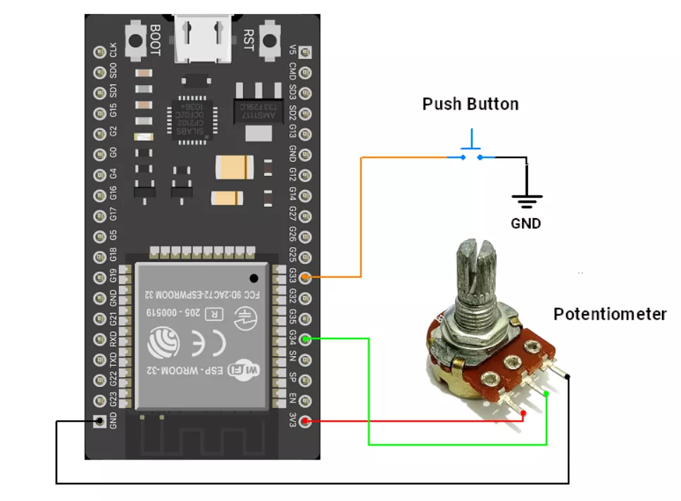
ESP32 Circuit Connection
- Interface potentiometer to GPIO pin 34.
- Interface the push button switch with an internal pull-up enable to the GPIO pin 33.
ESP32 Firmware Implementation
Code
#include <esp_sleep.h>

#define WAKEUP_PIN 33   // RTC-capable GPIO for wake-up
#define ADC_PIN 34      // GPIO34 (ADC1 channel 6), input-only, ideal for ADC

bool isPressed = false;

void setup() {
  Serial.begin(115200);
  delay(100);  // Allow time for Serial connection

  // Determine wakeup reason
  if (esp_sleep_get_wakeup_cause() == ESP_SLEEP_WAKEUP_EXT0) {
    isPressed = true;
  }
  if (isPressed) {
    int adcValue = analogRead(ADC_PIN);
    Serial.print("ADC value: ");
    Serial.println(adcValue);
    delay(10);
    isPressed = false;
  }

  // Configure wakeup with internal pull-up
  pinMode(WAKEUP_PIN, INPUT_PULLUP);  // Ensure button connects to GND when pressed
  esp_sleep_enable_ext0_wakeup((gpio_num_t)WAKEUP_PIN, 0); // Wake on LOW level

  // Optional debounce delay
  delay(50);

  // Enter deep sleep
  Serial.println("Entering deep sleep...");
  Serial.flush();
  esp_deep_sleep_start();
}

void loop() {
  // Empty - ESP32 never reaches loop() after deep sleep, code restarts at setup()
}
Code Explanation
Logic of the Code
- On startup, ESP32 checks the wake-up reason. If it woke due to the button press, it sets a flag.
- After waking up, it reads the ADC value from the sensor and prints it on the Serial Monitor.
- The button pin is configured as a wake-up source with internal pull-up, triggering on a LOW Level (button pressed).
- ESP32 enters deep sleep to save power.
- On the next button press, ESP32 wakes up and repeats the cycle.
Some Important Functions to Understand
esp_sleep_enable_ext0_wakeup(pin, level);
Configures a GPIO pin as an external wake-up source. Wakes on HIGH or LOW level.esp_sleep_get_wakeup_cause();
Returns the reason ESP32 woke up (e.g., external GPIO, timer, etc.).esp_deep_sleep_start();
Puts ESP32 into deep sleep mode. Code execution stops and resumes at setup() after wake-up.
Power Saving Analysis
- Active Mode Consumption: ~50 mA.
- Sleep Mode Consumption: ~10 mA.
- Power Reduction: A Significant decrease in the current draw by enabling sleep mode.
- Conclusion: Implementing sleep mode enhances energy efficiency.
Note: The analysis was performed using a USB voltage/current meter. Due to the additional peripherals present on the development board, the measured values are higher than the theoretical power consumption of the ESP32 chip alone.
We are using the Arduino UNO development board and programming it using the Arduino IDE.
- Before uploading, make sure to select “Arduino UNO” as the board to ensure correct settings and compatibility.
From the task, we understand that,
- Low-power operation: The system stays in a low-power state, waking up only when the push button is pressed.
- Minimal power consumption: Ensures the system consumes very little power during idle periods.
- Power-down Sleep Mode: Utilizes the highest power savings available on the ATmega328P (Arduino UNO).
- User interaction: The system wakes up and processes data only when the user interacts via the button press.
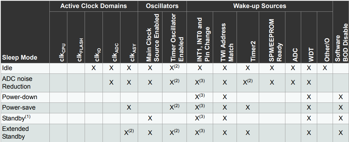
The Arduino UNO (ATmega328P) supports six sleep modes, each offering different power-saving levels:
- IDLE Mode – Lowest power saving, CPU stops, but peripherals (Timer, ADC, Serial, etc.) keep running. Fast wake-up.
- ADC Noise Reduction Mode – Reduces noise for ADC conversions by stopping the CPU and some peripherals.
- Power-down Mode – Maximum power saving; Only an external reset, watchdog reset/interrupt, brown-out reset, 2-wire serial interface match, INT0/INT1 level interrupt, or pin change interrupt can wake the MCU. All generated clocks halt, except for asynchronous modules.
- Power-save Mode – Similar to Power-down, but allows Timer2 to keep running for periodic wake-ups.
- Standby Mode – Like Power-down, but with an active oscillator for faster wake-up.
- Extended Standby Mode – Same as Standby, but keeps Timer2 running for periodic tasks.
For best power efficiency, use Power-down Mode with external interrupts for wake-up.
Here is a comparison of all sleep modes available in the Arduino UNO (ATmega328P):
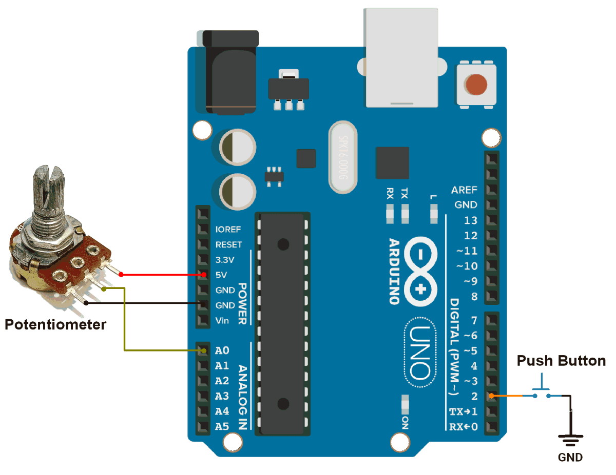
Arduino UNO Hardware Connection
- Connect the Arduino UNO board to the PC using a USB cable to establish communication with the Serial Monitor.
- Push Button:
- Connected to D2 (INT0) for an external interrupt.
- One terminal is connected to GND.
- The other terminal is connected to D2 with an internal pull-up resistor (avoiding an external pull-up).
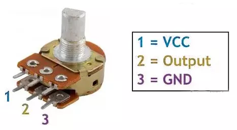
- Potentiometer:
- Terminal 1 → Vcc.
- Terminal 2 → Pin A0.
- Terminal 3 → GND.
Circuit Connection
Arduino UNO Firmware Implementation
Before writing the firmware, let’s break down the key functionalities:
- Sleep Mode Implementation
- The Arduino UNO (ATmega328P) supports various sleep modes.
SLEEP_MODE_PWR_DOWNis the lowest power mode, turning off everything except external interrupts.- The
sleep_bod_disable()function disables the Brown-Out Detector (BOD), further reducing power consumption.
- External Interrupt for Wake-Up
- The system remains in sleep mode and wakes up when the button is pressed.
- Interrupt 0 (INT0) on pin D2 is configured to trigger on a falling edge (when the button is pressed).
- ADC Measurement After Wake-Up
- After waking up, the system reads the ADC value from the potentiometer (A0).
- The value is printed to the Serial Monitor for monitoring.
- Returning to Sleep Mode
- After printing the ADC value, the system re-enters sleep mode, waiting for the next button to be pressed.
Code
#include <avr/sleep.h>
#include <avr/power.h>
#include <avr/interrupt.h>

#define INT0_PIN 2  // External Interrupt (D2)
#define ADC_PIN A0  // ADC Input Pin
#define DEBOUNCE_DELAY 50

bool isPressed = false;

void wakeUpISR() {
  // Empty ISR, just needed to wake the microcontroller
}

void setup() {
  pinMode(13, OUTPUT);
  digitalWrite(13, LOW);  //Turning off the on board LED for power saving
  pinMode(INT0_PIN, INPUT_PULLUP);
  attachInterrupt(digitalPinToInterrupt(INT0_PIN), wakeUpISR, FALLING);
}

void enterSleepMode() {
  set_sleep_mode(SLEEP_MODE_PWR_DOWN);  // Set sleep mode
  cli();                                // Disable interrupts to avoid race conditions
  sleep_enable();
  sleep_bod_disable();  // Disable Brown-Out Detector for lower power
  sei();                // Re-enable interrupts
  sleep_mode();         // Enter sleep mode (Execution stops here)

  // Code resumes here after wake-up
  sleep_disable();

  delay(DEBOUNCE_DELAY);
  if (digitalRead(2) == LOW)
    isPressed = true;
}

void loop() {
  enterSleepMode();  // Sleep until button press
  if (isPressed) {
    Serial.begin(115200);  // Restore Serial after wake-up
    Serial.print("ADC value: ");
    Serial.println(analogRead(ADC_PIN));  // Print ADC value after waking up
    delay(10);                            // Allow time for stability
    isPressed = false;
  }
}
Code Explanation
Setup Function (setup()):
- Configure Pin D2 as
INPUT_PULLUP. - Attach External Interrupt (
INT0) towakeUpISR()with aFALLINGedge trigger on Pin D2.
Sleep Mode (enterSleepMode()):
- Set the Power-down sleep mode for power savings.
- Temporarily disable interrupts with
cli(). - Enable sleep mode and disable BOD for further savings.
- Re-enable interrupts with
sei()and enter sleep usingsleep_mode().
Debouncing Handling:
delay(DEBOUNCE_DELAY): Handles button debounce.digitalRead(2) == LOW: Checks if button is pressed.isPressed = true: Flags a valid button press.
Loop Function (loop()):
- Call
enterSleepMode()to enter low-power state. - After waking up, read the ADC value from the potentiometer and print.
- Add a small delay for stability before repeating the cycle.
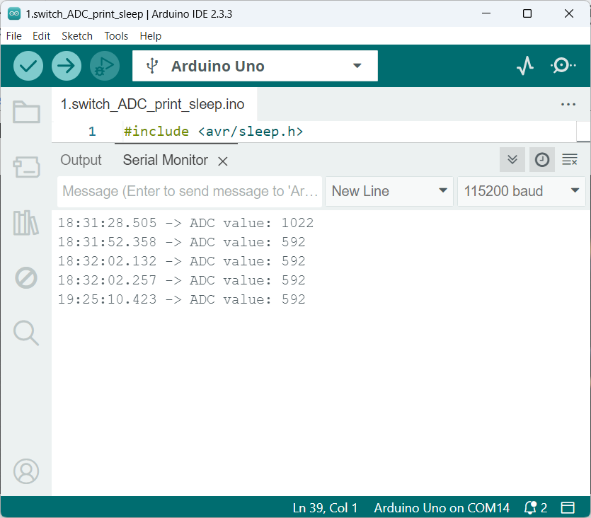
Output
Power Saving Analysis
- Active Mode Consumption: 25-30 mA.
- Sleep Mode Consumption: 14-17 mA.
- Power Reduction: A Significant decrease in the current draw by enabling sleep mode.
- Conclusion: Implementing sleep mode enhances energy efficiency.
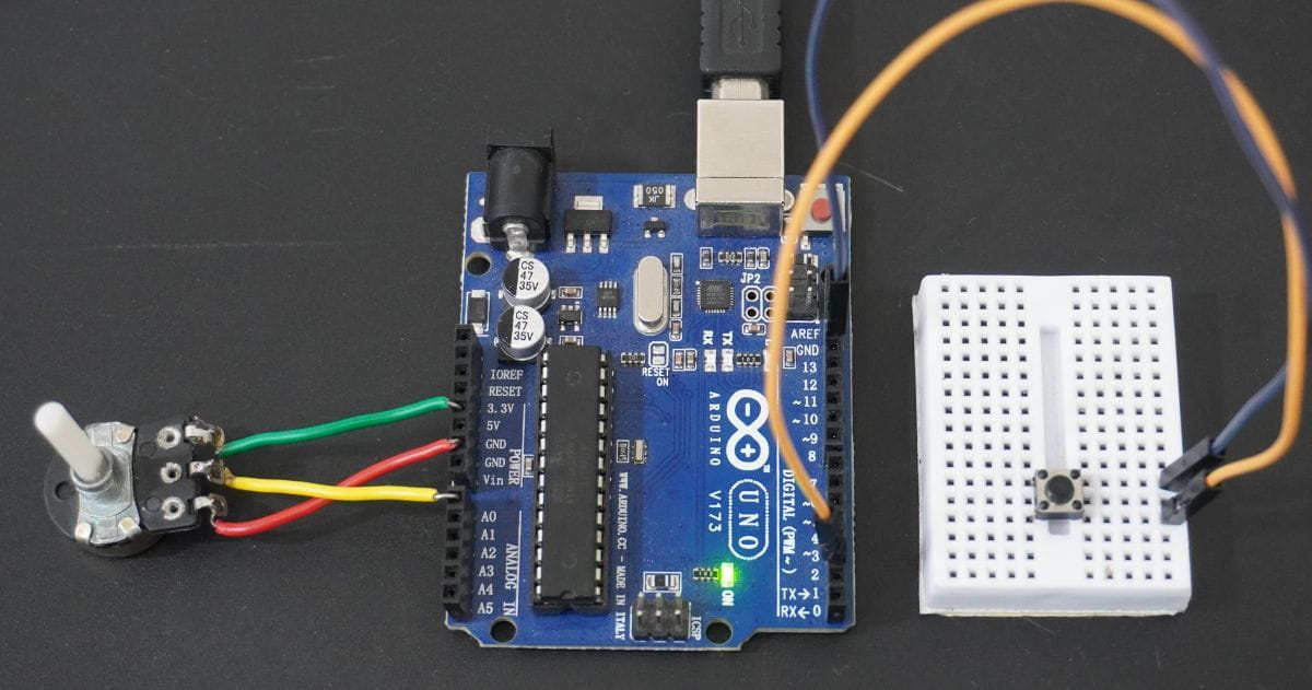
Hardware Setup
Serial Monitor Output