57. User Define RTC Function For Time Reading
Let's understand the RTC first,
- A Real-Time Clock (RTC) monitors time and maintains a calendar.
- We are going to use the DS1307 RTC module, which works on the I2C protocol at 100KHz speed with a 7-bit slave address of 0x68, typically.
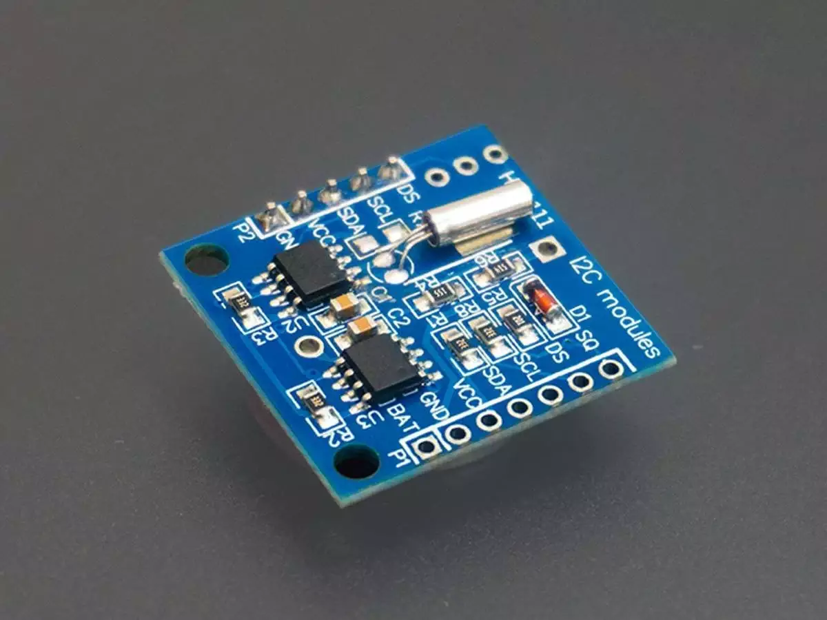
RTC Module(DS1307)
Pinout of DS1037 RTC module
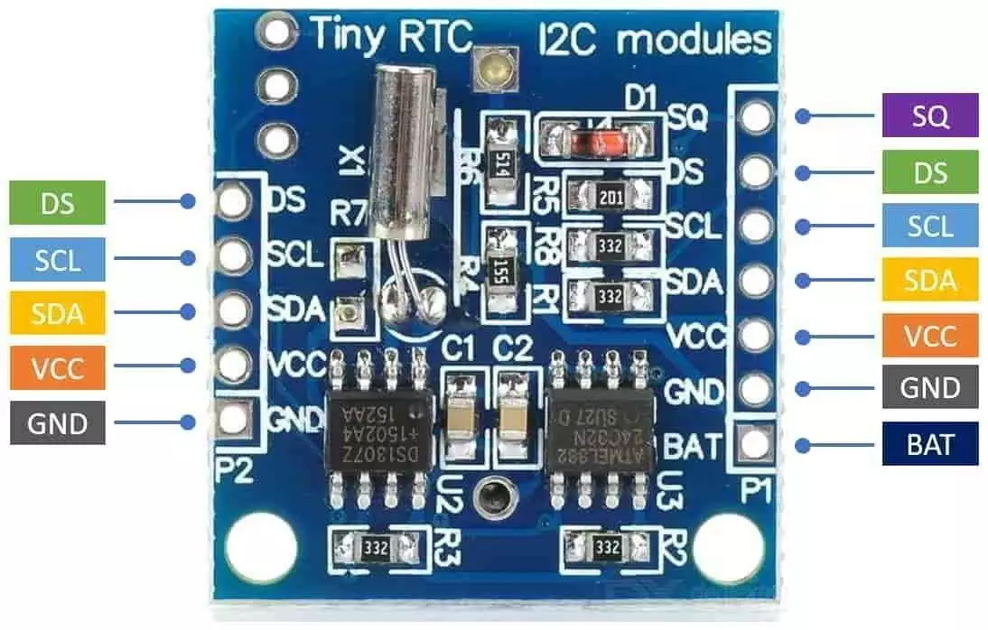
- The breakout board of this module has pins on both sides for ease of use. We will only use the 5 pins shown on the left side of the image.
- When powered ON for the first time, we might read random date and time values from the RTC module. So we must first program it with the current date and time.
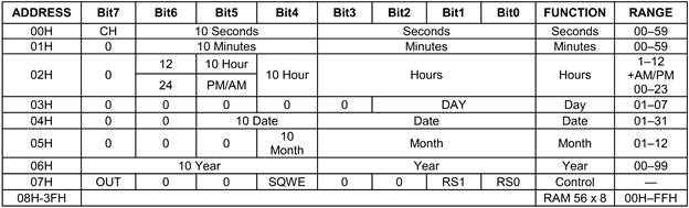
- The data stored in the RTC module is in BCD format.
- Shown in the image below are the contents of the Timekeeper registers. There are eight registers in total. Once we set their values, they will keep updating themselves.
Datasheet: EW Skill Attachment DS1307-3421066 datasheet
To know more about the DS1307 module, please read the RTC (Real Time Clock ) DS1307 Module
Now we will interface this module with a microcontroller
Interfacing Steps
- Hardware Connections
- Connect the SDA and SCL pins of DS1307 to the corresponding I2C pins on the microcontroller.
- Add 4.7kΩ pull-up resistors between SDA/SCL and VCC.
- Also, we can use internal pull-up resistors.
- Connect VCC 3.3V or 5V, depending on the MCU voltage level, and GND appropriately.
Note: When interfacing I²C devices operating at different voltages (e.g., 5 V ↔ 3.3 V), always use a voltage level shifter to ensure safe logic levels and reliable communication.
- I2C Initialization
- Configure the I2C peripheral of the microcontroller for 100 kHz Standard Mode.
- Set the microcontroller as an I2C Master and DS1307 as an I2C Slave (0x68).
- Reading Time from DS1307
- Send the starting register address (0x00 for seconds).
- Read 3 consecutive bytes (Seconds, Minutes, Hours).
- Convert the BCD values to decimal.
- Displaying Time on Serial Terminal
- Format the time as
HH:MM:SS. - Print via UART to PuTTY/Arduino IDE.
- Format the time as
So, by connecting and configuring the master and slave devices and the I2C communication, we can implement the task.
Below are the solutions to the given task using different microcontrollers
- STM32
- ESP32
- Arduino UNO
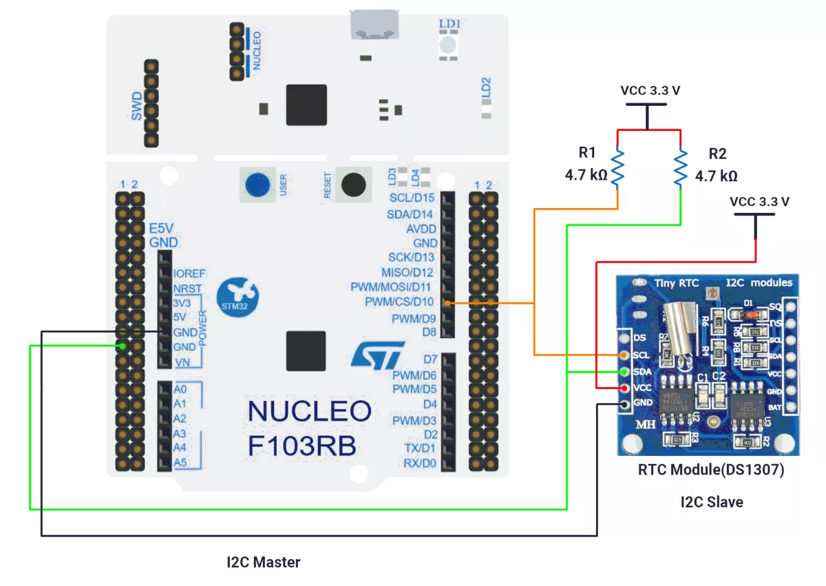
We’re using an STM32 NUCLEO-F103RB board as a master, which operates at a 3.3V logic level.
Key Peripherals Used:
- I2C1 – Facilitates I2C communication between the Master and Slave.
- USART2 – Provides serial communication with a terminal for displaying messages.
STM32 Hardware Connection
- Connect PB6 → SCL pin of the Slave.
- Connect PB7 → SDA pin of the Slave.
- Ensure a shared GND between the Master and Slave.
- Place 4.7 kΩ pull-up resistors between VCC 3.3V and each of the SDA and SCL lines.
- Connect the USB cable to the PC for power and UART communication.
Note: RTC DS1307 Breakout Power & Logic Levels
In our DS1307 breakout board, the onboard pull-up resistors connect SDA/SCL to VCC.
- When RTC is powered at 5 V, the I²C lines are pulled up to 5 V, which can damage 3.3 V controllers (ESP32/STM32).
- For demonstration, we powered the module at 3.3 V, which keeps logic levels safe but is not recommended for long-term use, since the DS1307 is specified for 4.5–5.5 V and may lose accuracy below this range.
Recommended practice: Power the DS1307 at 5 V and use an I²C level shifter for safe, reliable operation.
Circuit Diagram
STM32 Firmware Implementation
Project Setup in STM32CubeIDE
- Create a Project
- Open STM32CubeIDE, start a new project, and select the NUCLEO-F103RB board.
- Basic Configuration (via CubeMX inside CubeIDE)
- Clock: Use the default HSI oscillator with PLL enabled (as configured in
SystemClock_Config). - GPIO: Enable clocks for PORTA, PORTB, PORTC, and PORTD.
- I2C1: I2C mode (Standard mode, 100kHz clock).
- USART2: Enabled at 115200 baud, 8-N-1, for debugging/expansion if needed.
- Clock: Use the default HSI oscillator with PLL enabled (as configured in
- Code Generation
- CubeMX will automatically generate all the startup code, including:
HAL_Init()→ Initializes HAL and system tick.SystemClock_Config()→ Configures system clock (HSI + PLL).MX_GPIO_Init()→ Initializes GPIO ports.MX_USART2_UART_Init()→ Configures UART2.MX_I2C1_Init()→ Configures I2C1.
- This code sets up the hardware and prepares the project for firmware development, so we only need to add our application logic in the user code sections
- CubeMX will automatically generate all the startup code, including:
Code Snippets from main.c
I2C Initialization (MX_I2C1_Init)
hi2c1.Instance = I2C1;
hi2c1.Init.ClockSpeed = 100000;       // 100kHz
hi2c1.Init.DutyCycle = I2C_DUTYCYCLE_2;
hi2c1.Init.AddressingMode = I2C_ADDRESSINGMODE_7BIT;
if (HAL_I2C_Init(&hi2c1) != HAL_OK) {
  Error_Handler();
}- Initializes I2C1 peripheral with 100kHz clock speed, standard duty cycle, and 7-bit addressing mode.
Header includes
#include <stdio.h> → For snprintf (string formatting)
#include <string.h> → For strlen (string length operations)
Private defines
#define RTC_ADDR (0x68 << 1) → RTC I2C address (7-bit shifted left for HAL compatibility).
Utility Function
uint8_t bcdToDec(uint8_t val) {
   return ((val >> 4) * 10 + (val & 0x0F));
}

uint8_t decToBcd(uint8_t val) {
   return ((val / 10) << 4) | (val % 10);
}bcdToDec(val)→ Converts BCD (Binary-Coded Decimal) to decimal.decToBcd(val)→ Converts decimal to BCD.
User-defined RTC Functions
A) Start RTC
// Start RTC by clearing CH (Clock Halt) bit
void rtcStart(void) {
   uint8_t sec;
   if (HAL_I2C_Mem_Read(&hi2c1, RTC_ADDR, 0x00, I2C_MEMADD_SIZE_8BIT, &sec, 1, 100) == HAL_OK) {
       sec &= 0x7F; // Clear CH bit
       HAL_I2C_Mem_Write(&hi2c1, RTC_ADDR, 0x00, I2C_MEMADD_SIZE_8BIT, &sec, 1, 100);
       HAL_UART_Transmit(&huart2, (uint8_t *)"RTC Start\r\n", 11, HAL_MAX_DELAY);
   } else {
       HAL_UART_Transmit(&huart2, (uint8_t *)"RTC Comm Error\r\n", 17, HAL_MAX_DELAY);
   }
}- rtcStart:
- Reads the seconds register (0x00) from the RTC.
- Clears the CH (Clock Halt) bit to start the oscillator.
- Write the modified seconds back.
- Sends “RTC Start” or “RTC Comm Error” over UART for status.
B) Read and Print Time
// Read time and convert to 12-hour format
void readAndPrintTime(void) {
   uint8_t data[3];
   char buffer[64];
   if (HAL_I2C_Mem_Read(&hi2c1, RTC_ADDR, 0x00, I2C_MEMADD_SIZE_8BIT, data, 3, 100) == HAL_OK) {
       uint8_t second = bcdToDec(data[0] & 0x7F); // Clear CH bit
       uint8_t minute = bcdToDec(data[1]);
       uint8_t hourRaw = data[2];
       uint8_t hour, hourVal;
       const char *ampm;
       if (hourRaw & 0x40) {
           // 12-hour format
           hourVal = bcdToDec(hourRaw & 0x1F);
           ampm = (hourRaw & 0x20) ? "PM" : "AM";
           hour = hourVal;
       } else {
           // 24-hour format
           hourVal = bcdToDec(hourRaw & 0x3F);
           if (hourVal == 0) {
               hour = 12;
               ampm = "AM";
           } else if (hourVal < 12) {
               hour = hourVal;
               ampm = "AM";
           } else {
               hour = (hourVal == 12) ? 12 : hourVal - 12;
               ampm = "PM";
           }
       }
       snprintf(buffer, sizeof(buffer), "Time: %02d:%02d:%02d %s\r\n", hour, minute, second, ampm);
   } else {
       snprintf(buffer, sizeof(buffer), "RTC Read Error\r\n");
   }
   HAL_UART_Transmit(&huart2, (uint8_t *)buffer, strlen(buffer), HAL_MAX_DELAY);
}- readAndPrintTime:
- Reads seconds, minutes, and hours registers starting at 0x00.
- Converts BCD to decimal and handles both 12-hour and 24-hour formats:
- If the 12-hour mode bit is set, it extracts the hour and AM/PM.
- If 24-hour mode, converts to 12-hour with correct AM/PM.
- Formats time as “Time: HH:MM:SS AM/PM” and transmits via UART; on read error, prints “RTC Read Error”.
Main Loop Logic
  HAL_Delay(1000);
  rtcStart();

  while (1)
  {
    readAndPrintTime();
    HAL_Delay(1000);
}- Initial delay (
HAL_Delay(1000)) → Allows hardware stabilization. - rtcStart() → Ensures RTC is running.
- Infinite loop:
- Reads and prints time every second (HAL_Delay(1000)).
Expected Output
The UART terminal will display either:
- Formatted time: "
Time: HH:MM:SS AM/PM" - Or error messages: "RTC Comm Error" or "RTC Read Error"
To set time manually we can use below function
Set Time and Date (User-Defined Function)
void DS1307_SetTimeAndDate(uint8_t hour, uint8_t minute, uint8_t second) {
    uint8_t rtc_data[3];

    rtc_data[0] = decToBcd(second);                // Seconds
    rtc_data[1] = decToBcd(minute);                // Minutes
    rtc_data[2] = decToBcd(hour);                  // Hours (24-hour format)

    HAL_I2C_Mem_Write(&hi2c1, RTC_ADDR, 0x00, I2C_MEMADD_SIZE_8BIT, rtc_data, 3, HAL_MAX_DELAY);
}
This function sets the DS1307 RTC time and date via I²C. It takes hours, minutes, seconds as inputs, converts them from decimal to BCD (as required by DS1307), and writes all 3 bytes (seconds → hours) starting from register 0x00 using HAL_I2C_Mem_Write.
Example:
DS1307_SetTimeAndDate(14, 33, 22); // Sets 14:33:22Download Project
The complete STM32CubeIDE project (including .ioc configuration, main.c, and HAL files) is available here:
📥 Download Project
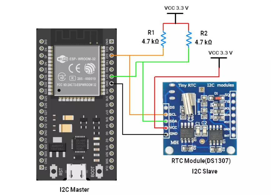
We are using the ESP32 DevKit v4 development board and programming it using the Arduino IDE.
- Before uploading, make sure to select “ESP32 Dev Module” as the board to ensure correct settings and compatibility.
In both ESP32 master and slave codes, the Wire.h the library is used for I²C communication.
Circuit Connection
- Connect 22 ➔ SCL of all slaves.
- Connect 21 ➔ SDA of all slaves.
- Common GND of ESP32 ➔ RTC GND.
- Place 4.7 kΩ pull-up resistors between VCC(3.3V) and each of the SDA and SCL lines.
Note: RTC DS1307 Breakout Power & Logic Levels
In our DS1307 breakout board, the onboard pull-up resistors connect SDA/SCL to VCC.
- When RTC is powered at 5 V, the I²C lines are pulled up to 5 V, which can damage 3.3 V controllers (ESP32/STM32).
- For demonstration, we powered the module at 3.3 V, which keeps logic levels safe but is not recommended for long-term use, since the DS1307 is specified for 4.5–5.5 V and may lose accuracy below this range.
Recommended practice: Power the DS1307 at 5 V and use an I²C level shifter for safe, reliable operation.
Firmware Implementation
- To read the time value from the RTC module and to set the time initially, we have created our custom function instead of using the ready-to-use library.
- First, we have to set the time in the RTC module.
- Given below are the codes to set the time and read time from the RTC module.
ESP32 as Master Code(To set time in RTC)
#include <Wire.h>

// DS1307 I2C address
#define rtc_addr 0x68
uint8_t error_code;

// Default I2C pins for ESP32
#define I2C_SDA 21
#define I2C_SCL 22

void setup() {
  Serial.begin(115200);
  Wire.begin(I2C_SDA, I2C_SCL);  // Initialize I2C with custom pins

  uint8_t rtc_response = 1;
  Serial.print("Device scanning...");

  // Scan for RTC with timeout (max 50 attempts = 5 seconds)
  for (int attempts = 0; attempts < 50 && rtc_response != 0; attempts++) {
    rtc_response = rtcResponding();
    Serial.print(".");
    delay(100);
  }

  if (rtc_response == 0) {
    setTime(11, 11, 0);  // Set RTC time (hour=0-23, min=0-59, sec=0-59)

    if (!error_code) {
      Serial.println("\nRTC device found");
      Serial.println("Time set successfully");
    } else {
      Serial.println("\nCommunication error - time not set");
    }
  } else {
    Serial.println("\nRTC not found! Check wiring");
  }
}

void loop() {
  // Your main code can go here
}

// Convert BCD to decimal
int bcdToDec(byte val) {
  return (val >> 4) * 10 + (val & 0x0F);
}

// Convert decimal to BCD
byte decToBcd(int val) {
  return ((val / 10) << 4) | (val % 10);
}

// Set time on DS1307
void setTime(int hour, int minute, int second) {
  Wire.beginTransmission(rtc_addr);
  Wire.write(0x00);                         // Seconds register
  Wire.write(decToBcd(second));             // Set seconds
  Wire.write(decToBcd(minute));             // Set minutes
  Wire.write(decToBcd(hour));               // Set hours (24-hour format)
  error_code = Wire.endTransmission(true);  // true = send stop
}

// Check RTC presence
uint8_t rtcResponding() {
  Wire.beginTransmission(rtc_addr);
  return Wire.endTransmission(true);  // true = send stop
}
Code Explanation
- void
readTime(int &hour, int &minute, int &second, String &period);Function used to read the time from the DS1307 RTC module. We first send the register address, and then read the content of each register one by one. void rtcStart(void):It is used to start the RTC module. The CH (Clock Halt) bit of the 0x00h address register is cleared to enable the RTC oscillator.- Code to set the RTC time initially
- We use the
setTime();function invoid setup()to initially set the time in the RTC. uint8_t rtcResponding();Check whether the device is present in the network or not.- This code is uploaded once to configure the RTC time.
- After the time is set, we upload the Arduino master code.
- We use the
ESP32 as Master Code(To read time from RTC)
#include <Wire.h>

// ---------- Types ----------
struct RtcFields {
  uint8_t sec, min, hour;            // display hour (12 h), minute, second
  bool is12h;                        // true if RTC is in 12 h mode
  bool pm;                           // valid only if is12h==true; else derived from 24 h
  uint8_t dayOfWeek, date, month, year2d; // DOW: 1..7, date: 1..31, month: 1..12, year: 00..99
};

// ---------- Prototypes ----------
bool rtcStartClock();  // clears CH bit (starts oscillator) without altering seconds
bool rtcSetTime(uint8_t sec, uint8_t min, uint8_t hour24,
                uint8_t dayOfWeek, uint8_t date, uint8_t month, uint8_t year2d);
bool rtcGet(RtcFields &t);           // burst-read and parse time/date registers
void printTimeLine(const RtcFields &t);

// ---------- Globals/Consts ----------
static const uint8_t RTC_ADDR = 0x68; // 7-bit I²C address (DS1307)

// --- BCD helpers: DS1307 stores time/date in BCD ---
static inline uint8_t decToBcd(uint8_t v) { return ((v / 10) << 4) | (v % 10); }
static inline uint8_t bcdToDec(uint8_t v) { return ((v >> 4) * 10) + (v & 0x0F); }

// Minimal I²C write with small retry for bus contention/transient NACKs
bool i2cWrite(uint8_t dev, const uint8_t* data, size_t len, uint8_t retries = 2) {
  while (true) {
    Wire.beginTransmission(dev);
    Wire.write(data, len);
    uint8_t e = Wire.endTransmission(true);   // send STOP
    if (e == 0) return true;                  // success
    if (retries-- == 0) return false;         // Data is not send successfully
    delay(2);
  }
}

bool i2cWrite1(uint8_t dev, uint8_t b) {
  return i2cWrite(dev, &b, 1);
}

// DS1307 block write
bool rtcWriteRegs(uint8_t startReg, const uint8_t* buf, size_t n) {
  uint8_t tmp[1 + 8];                 // DS1307 timekeeper burst ≤ 7 bytes; keep small headroom
  if (n > 8) return false;
  tmp[0] = startReg;
  memcpy(&tmp[1], buf, n);
  return i2cWrite(RTC_ADDR, tmp, n + 1);
}

// DS1307 block read using register pointer then repeated START
bool rtcReadRegs(uint8_t startReg, uint8_t* buf, size_t n) {
  if (!i2cWrite1(RTC_ADDR, startReg)) return false;          // set register pointer
  uint8_t read = Wire.requestFrom(RTC_ADDR, (uint8_t)n, true); // read N bytes + STOP
  if (read != n) return false;                               // guard against short reads
  for (size_t i = 0; i < n; ++i) buf[i] = Wire.read();
  return true;
}

//Ensure oscillator is running: clear CH (bit7 of seconds) without changing seconds
bool rtcStartClock() {
  uint8_t sec;
  if (!rtcReadRegs(0x00, &sec, 1)) return false;
  sec &= 0x7F;                                // CH=0 -> start clock
  uint8_t pkt[2] = {0x00, sec};
  return i2cWrite(RTC_ADDR, pkt, 2);
}

// Program time/date in 24 h mode (bit6=0). dayOfWeek is user-defined (1..7)
bool rtcSetTime(uint8_t sec, uint8_t min, uint8_t hour24,
                uint8_t dayOfWeek, uint8_t date, uint8_t month, uint8_t year2d) {
  uint8_t regs[7];
  regs[0] = decToBcd(sec & 0x7F);            // ensure CH=0
  regs[1] = decToBcd(min);
  regs[2] = decToBcd(hour24 & 0x3F);         // 24 h mode: bit6=0
  regs[3] = decToBcd(dayOfWeek);
  regs[4] = decToBcd(date);
  regs[5] = decToBcd(month);
  regs[6] = decToBcd(year2d);
  return rtcWriteRegs(0x00, regs, 7);
}

// Read and parse DS1307 time/date; handle both 12 h and 24 h encodings for hours
bool rtcGet(RtcFields &t) {
  uint8_t r[7];
  if (!rtcReadRegs(0x00, r, 7)) return false; // sec,min,hour,DOW,date,month,year

  // Seconds: bit7 is CH (clock halt); masked off
  t.sec  = bcdToDec(r[0] & 0x7F);
  t.min  = bcdToDec(r[1] & 0x7F);

  // Hours: handle mode (bit6) and AM/PM (bit5 when 12 h)
  uint8_t rawHour = r[2];
  t.is12h = (rawHour & 0x40) != 0;
  if (t.is12h) {
    t.pm   = (rawHour & 0x20) != 0;
    t.hour = bcdToDec(rawHour & 0x1F);       // 1..12 as stored
  } else {
    uint8_t h24 = bcdToDec(rawHour & 0x3F);  // 0..23
    t.pm   = (h24 >= 12);
    // Convert to 12 h for display (01..12)
    t.hour = (h24 == 0) ? 12 : (h24 > 12 ? (uint8_t)(h24 - 12) : h24);
  }

  t.dayOfWeek = bcdToDec(r[3]);              // DS1307 does not validate DOW; user-defined
  t.date      = bcdToDec(r[4]);
  t.month     = bcdToDec(r[5]);
  t.year2d    = bcdToDec(r[6]);
  return true;
}

// Human-readable single-line print: "HH:MM:SS AM  DD/MM/YY"
void printTimeLine(const RtcFields &t) {
  char buf[40];
  snprintf(buf, sizeof(buf), "%02u:%02u:%02u %s  %02u/%02u/%02u",
           t.hour, t.min, t.sec, t.pm ? "PM" : "AM", t.date, t.month, t.year2d);
  Serial.println(buf);
}

void setup() {
  Serial.begin(115200);
  Wire.begin(21, 22);           // ESP32 default I²C pins
  Wire.setClock(100000);        // Standard mode (DS1307 spec)
  if (!rtcStartClock()) Serial.println("RTC start failed");

  // OPTIONAL: set ONCE then comment out to avoid resetting the RTC on every boot.
  // Example below sets: 14:25:00, DOW=2, 02/09/25  (YY=25)
  // rtcSetTime(0, 25, 14, 2, 2, 9, 25);
}

void loop() {
  RtcFields t;
  if (rtcGet(t)) {
    printTimeLine(t);
  } else {
    Serial.println("RTC read error");
  }
  delay(1000);
}
Code Explanation
- Initialization
rtcStartClock()→ Reads the seconds register, clears CH (Clock Halt, bit7), and writes it back to ensure the oscillator is running.rtcSetTime(...)(optional, only once) → Programs initial time/date values into DS1307 registers.
- Loop Execution
rtcGet(t)→ Reads 7 bytes (sec, min, hour, day-of-week, date, month, year) starting at register0x00.- Converts BCD → decimal values for each field.
- Checks bit 6 of the hours register to detect 12 h or 24 h mode.
- If in 12 h mode → extracts AM/PM (bit5) and hour (bits0–4).
- If in 24 h mode → converts to 12 h display (1–12) and sets AM/PM flag in software.
printTimeLine(t)→ Formats and prints:HH:MM:SS AM DD/MM/YY- Functions
bcdToDec()→ Converts a Binary Coded Decimal (e.g., 0x49) into normal decimal (49).decToBcd()→ Converts decimal to BCD (used when setting the RTC).i2cWrite() / i2cWrite1()→ Low-level wrappers for sending data over I²C with retries.rtcWriteRegs(startReg, buf, n)→ Burst write of n registers starting at startReg.rtcReadRegs(startReg, buf, n)→ Burst read of n registers starting at startReg.rtcStartClock()→ Clears the CH bit in the seconds register, keeps other bits unchanged, ensuring the RTC ticks.rtcSetTime(ss, mm, hh, dow, dd, mm, yy)→ Programs all 7 DS1307 timekeeper registers in 24 h mode.rtcGet()→ Reads and parses all time/date registers into a user-friendly struct (RtcFields).printTimeLine()→ Prints the parsed struct in a human-readable format.
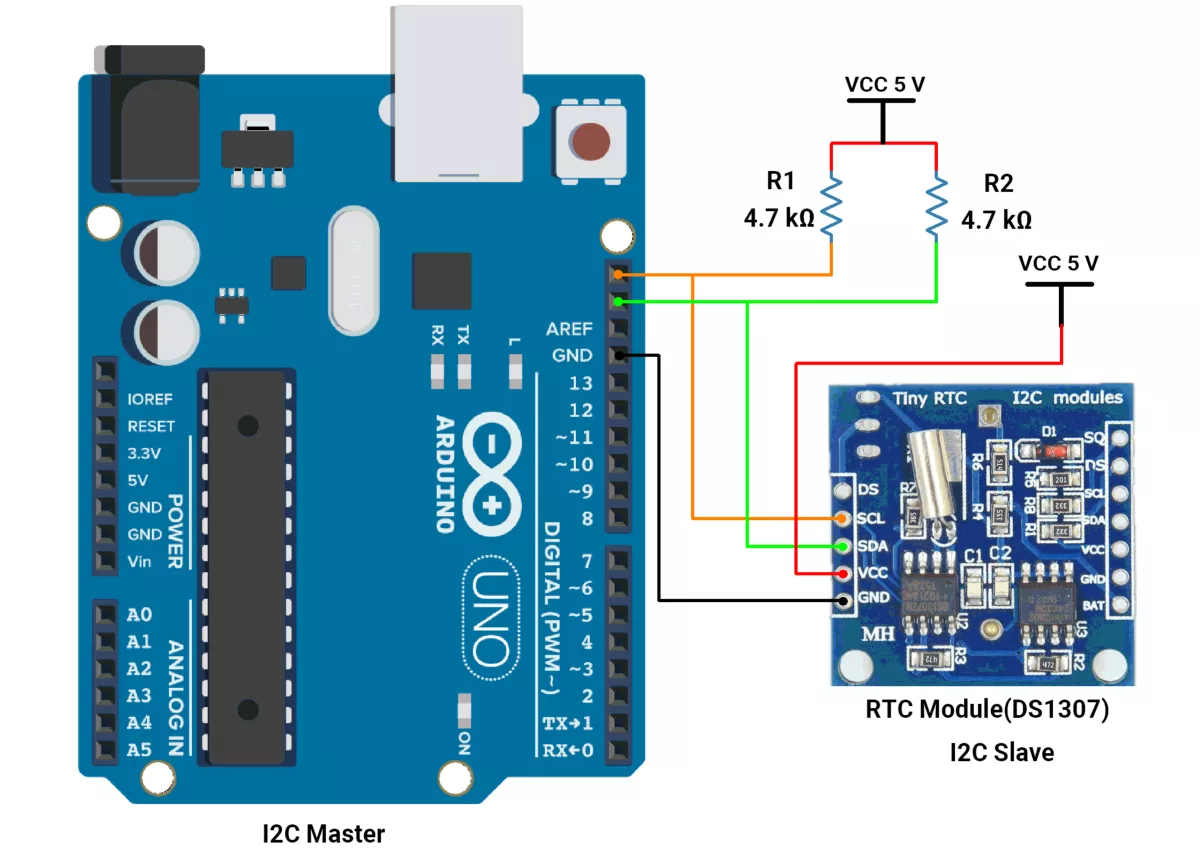
We are using the Arduino UNO development board and programming it using the Arduino IDE.
- Before uploading, make sure to select “Arduino UNO” as the board to ensure correct settings and compatibility.
In this task, Arduino UNO acts as an I2C master, and the RTC module acts as a slave.
I²C Pins Of Arduino UNO
- SDA → A4
- SCL → A5
First, let's establish the hardware connection.
Hardware Connection
- Connect A4 → SDA pin of the Slave.
- Connect A5 → SCL pin of the Slave.
- Ensure a shared GND between the Master and Slave.
- Place 4.7 kΩ external pull-up resistors between VCC 5V and each of the SDA and SCL lines.
- Connect the USB cable to the PC for power and UART communication.
Circuit Diagram
Arduino UNO Firmware Implementation
- Wire.h library is used for I2C communication between the slave(DS1307) and master(Arduino UNO).
- To read the time value from the RTC module and to set the time initially, we have created our user-defined function instead of using the ready-to-use library.
Arduino UNO as Master code
#include <Wire.h>

/* ===== Types =====
struct RtcFields {
  uint8_t sec, min, hour;   // hour is 1..12 (we render 12-hour format)
  bool is12h;               // true if RTC is in 12-hour mode
  bool pm;                  // true if PM (derived or read)
  uint8_t dayOfWeek,        // 1=Sun .. 7=Sat (per DS1307/DS3231)
          date,             // 1..31
          month,            // 1..12
          year2d;           // 00..99
};

/* ===== Prototypes ===== */
bool rtcStartClock();
bool rtcSetTime(uint8_t sec, uint8_t min, uint8_t hour24,
                uint8_t dayOfWeek, uint8_t date, uint8_t month, uint8_t year2d);
bool rtcGet(RtcFields &t);
void printTimeLine(const RtcFields &t);

/* ===== Globals / Consts ===== */
static const uint8_t RTC_ADDR = 0x68;   // DS1307/DS3231 I2C address

/* BCD helpers: DS1307/DS3231 store time in Binary-Coded Decimal */
static inline uint8_t decToBcd(uint8_t v) { return ((v / 10) << 4) | (v % 10); }
static inline uint8_t bcdToDec(uint8_t v) { return ((v >> 4) * 10) + (v & 0x0F); }

/* Low-level I2C write with small retry loop.
   Returns true on success (endTransmission == 0). */
bool i2cWrite(uint8_t dev, const uint8_t* data, size_t len, uint8_t retries = 2) {
  while (true) {
    Wire.beginTransmission(dev);
    Wire.write(data, len);
    uint8_t e = Wire.endTransmission(true);
    if (e == 0) return true;
    if (retries-- == 0) return false;
    delay(2);
  }
}

/* Single-byte variant */
bool i2cWrite1(uint8_t dev, uint8_t b) {
  return i2cWrite(dev, &b, 1);
  }

/* write RTC registers starting at 'startReg' */
bool rtcWriteRegs(uint8_t startReg, const uint8_t* buf, size_t n) {
  uint8_t tmp[1 + 8];              // fits 7 time regs plus start addr
  if (n > 8) return false;
  tmp[0] = startReg;
  memcpy(&tmp[1], buf, n);
  return i2cWrite(RTC_ADDR, tmp, n + 1);
}

/* read RTC registers starting at 'startReg' */
bool rtcReadRegs(uint8_t startReg, uint8_t* buf, size_t n) {
  if (!i2cWrite1(RTC_ADDR, startReg)) return false;               // set address pointer
  uint8_t read = Wire.requestFrom(RTC_ADDR, (uint8_t)n, (uint8_t)true);
  if (read != n) return false;
  for (size_t i = 0; i < n; ++i) buf[i] = Wire.read();
  return true;
}

/* Clear CH (Clock Halt) bit in seconds register to start the oscillator.
   Returns false if I2C fails. */
bool rtcStartClock() {
  uint8_t sec;
  if (!rtcReadRegs(0x00, &sec, 1)) return false;  // reg 0x00 = seconds
  sec &= 0x7F;                                    // clear CH (bit7)
  uint8_t pkt[2] = {0x00, sec};
  return i2cWrite(RTC_ADDR, pkt, 2);
}

/* Set full time/date in 24-hour input form.
   dayOfWeek: 1=Sun..7=Sat (device does not validate). */
bool rtcSetTime(uint8_t sec, uint8_t min, uint8_t hour24,
                uint8_t dayOfWeek, uint8_t date, uint8_t month, uint8_t year2d) {
  uint8_t regs[7];
  regs[0] = decToBcd(sec & 0x7F);           // keep CH=0
  regs[1] = decToBcd(min);
  regs[2] = decToBcd(hour24 & 0x3F);        // 24h mode (bit6=0), 0..23
  regs[3] = decToBcd(dayOfWeek);
  regs[4] = decToBcd(date);
  regs[5] = decToBcd(month);
  regs[6] = decToBcd(year2d);
  return rtcWriteRegs(0x00, regs, 7);
}

/* Read RTC and decode into RtcFields.
   Handles both 12h (RTC bit6=1) and 24h (bit6=0) hour formats. */
bool rtcGet(RtcFields &t) {
  uint8_t r[7];
  if (!rtcReadRegs(0x00, r, 7)) return false;

  uint8_t rawSec  = r[0] & 0x7F;   // mask out CH
  uint8_t rawMin  = r[1] & 0x7F;
  uint8_t rawHour = r[2];          // contains 12/24h flags

  t.sec  = bcdToDec(rawSec);
  t.min  = bcdToDec(rawMin);

  t.is12h = (rawHour & 0x40) != 0;                 // bit6: 1=12h
  if (t.is12h) {
    t.pm   = (rawHour & 0x20) != 0;                // bit5: 1=PM
    t.hour = bcdToDec(rawHour & 0x1F);             // 1..12
  } else {
    uint8_t h24 = bcdToDec(rawHour & 0x3F);        // 0..23
    t.pm   = (h24 >= 12);
    t.hour = (h24 == 0) ? 12 : (h24 > 12 ? (uint8_t)(h24 - 12) : h24); // to 12h view
  }

  t.dayOfWeek = bcdToDec(r[3]);
  t.date      = bcdToDec(r[4]);
  t.month     = bcdToDec(r[5]);
  t.year2d    = bcdToDec(r[6]);
  return true;
}

/* Print one human-readable line: "hh:mm:ss AM dd/mm/yy" */
void printTimeLine(const RtcFields &t) {
  char buf[40];
  snprintf(buf, sizeof(buf), "%02u:%02u:%02u %s  %02u/%02u/%02u",
           t.hour, t.min, t.sec, t.pm ? "PM" : "AM", t.date, t.month, t.year2d);
  Serial.println(buf);
}

void setup() {
  Serial.begin(115200);
  Wire.begin();  // UNO: SDA=A4, SCL=A5 (use external 4.7k pull-ups to VCC)

  if (!rtcStartClock()) Serial.println("RTC start failed");

  // ONE-TIME SET (uncomment, program once, then comment again)
  // rtcSetTime(0, 52, 13, 2, 2, 9, 25); // 13:52:00, Tue, 02/09/25
}

void loop() {
  RtcFields t;
  if (rtcGet(t)) printTimeLine(t);
  else Serial.println("RTC read error");
  delay(1000);
}

}
Let's understand the important function of code
rtcStartClock();- Starts the RTC by clearing the CH (Clock Halt) bit in the seconds register, enabling the oscillator.
rtcSetTime(sec, min, hour24, dayOfWeek, date, month, year2d);- Sets the DS1307 time and date registers. Uses 24-hour format for hours input.
rtcGet(RtcFields &t);- Reads 7 bytes from the RTC (seconds → year), converts BCD → decimal, and parses hour format (12h/24h, AM/PM). Returns the decoded time/date in RtcFields.
printTimeLine(const RtcFields &t);- Prints the formatted time/date (
HH:MM: SS AM DD/MM/YY) to the Serial Monitor.
- Prints the formatted time/date (
setup();- Initializes Serial and I²C, ensures RTC is running with
rtcStartClock(), and allows a one-time clock set using rtcSetTime().
- Initializes Serial and I²C, ensures RTC is running with
loop();- Calls
rtcGet()once per second and displays the time/date.
- Calls
Code to set the RTC time initially
- We use the
setTime()function invoid setup()to initially set the time in the RTC. - uint8_t rtcResponding(); Check whether the device is present in the network or not.
- This code is uploaded once in Arduino UNO to configure the RTC time.
- After the time is set, we will upload the Arduino master code to the Arduino UNO.
#include <Wire.h>
// DS1307 I2C address
#define rtc_addr 0x68
uint8_t error_code;
void setup() {
Serial.begin(115200);
Wire.begin();
// Disable internal pull-ups on SDA/SCL
pinMode(A4, INPUT); // SDA
pinMode(A5, INPUT); // SCL
digitalWrite(A4, LOW); // ensure pull-up is off
digitalWrite(A5, LOW); // ensure pull-up is off
uint8_t rtc_response;
Serial.print("Device scanning...");
while(rtc_response = rtcResponding()){
Serial.print(".");
delay(100);
}
setTime(15, 47, 0); // Set RTC time (min= 0-59, sec= 0-59, Hours = 00 to 23)
if (!error_code) {
Serial.println("\nRTC device found");
Serial.println("Time set successfully");
} else {
Serial.println("Time is not Set...");
}
}
void loop() {
}
// Function to convert BCD to decimal
int bcdToDec(byte val) {
return ((val / 16) * 10) + (val % 16);
}
// Function to convert decimal to BCD
byte decToBcd(int val) {
return (val / 10 * 16) + (val % 10);
}
// Function to set the time on the RTC DS1307
void setTime(int hour, int minute, int second) {
Wire.beginTransmission(rtc_addr); // communication start
Wire.write(0x00); // Start at the 0th register (seconds)
Wire.write(decToBcd(second)); // Set seconds
Wire.write(decToBcd(minute)); // Set minutes
Wire.write(decToBcd(hour)); // Set hours
error_code = Wire.endTransmission(); // transfer data and end communication
}
// Check RTC slave device present or not
uint8_t rtcResponding() {
Wire.beginTransmission(rtc_addr);
uint8_t response = Wire.endTransmission();
return response;
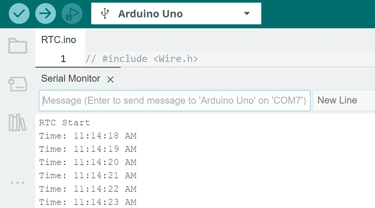
}OUTPUT
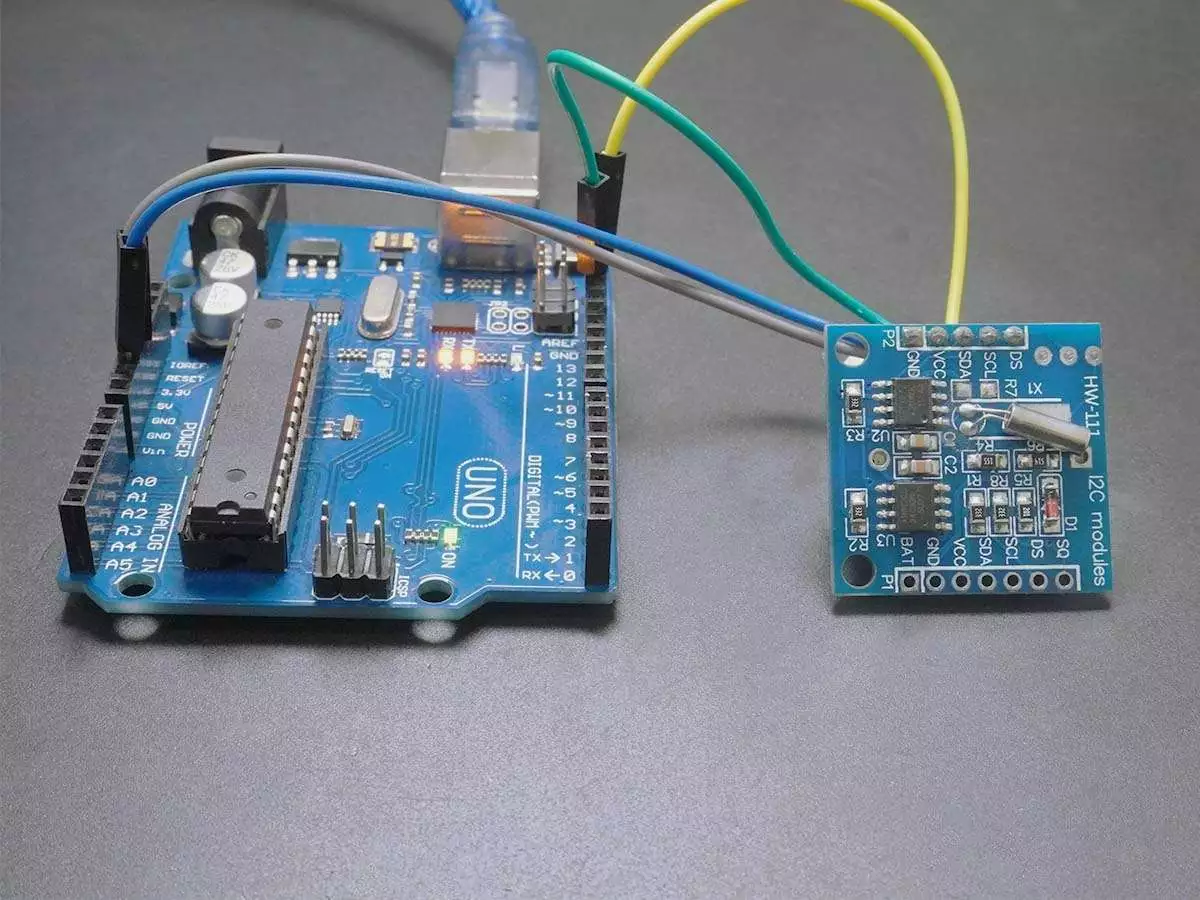
HARDWARE SETUP
Output Screen-shot
RTC Time Set
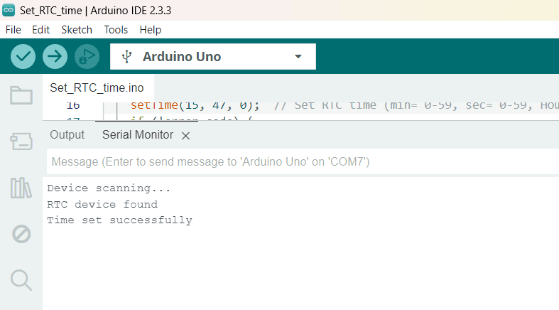
RTC Time Read
VIDEO
As we can see in the video, the time read from the RTC and printed on a serial monitor.