Capacitors Quick Reference Guide
What is a Capacitor?
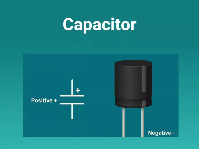
A capacitor is a passive two-terminal electrical component that stores electrical energy in an electric field. Its basic unit is the farad (F). In practice, capacitors are commonly found in microfarads (μF), nanofarads (nF), or picofarads (pF).
The amount of charge Q a capacitor stores is related to voltage V and capacitance C by:
Q = CV
Practical Use Cases of Capacitors
Capacitors are used in a variety of critical roles in hardware systems:
- Decoupling/Bypass Capacitors: Filter out noise from power supply lines to ICs
- Bulk Energy Storage: Hold up voltage in power supply rails during load transients
- Coupling and Blocking: Pass AC signals while blocking DC in amplifiers or filters
- Timing and Oscillation: Used with resistors in RC circuits or with crystals in oscillators
- Filtering: Smooth rectified signals in power supplies or form active/passive filters
- Snubber Circuits: Suppress switching noise in relay or motor driver circuits
- Charge Pumps & Switching Regulators: Energy transfer/storage in DC-DC converters
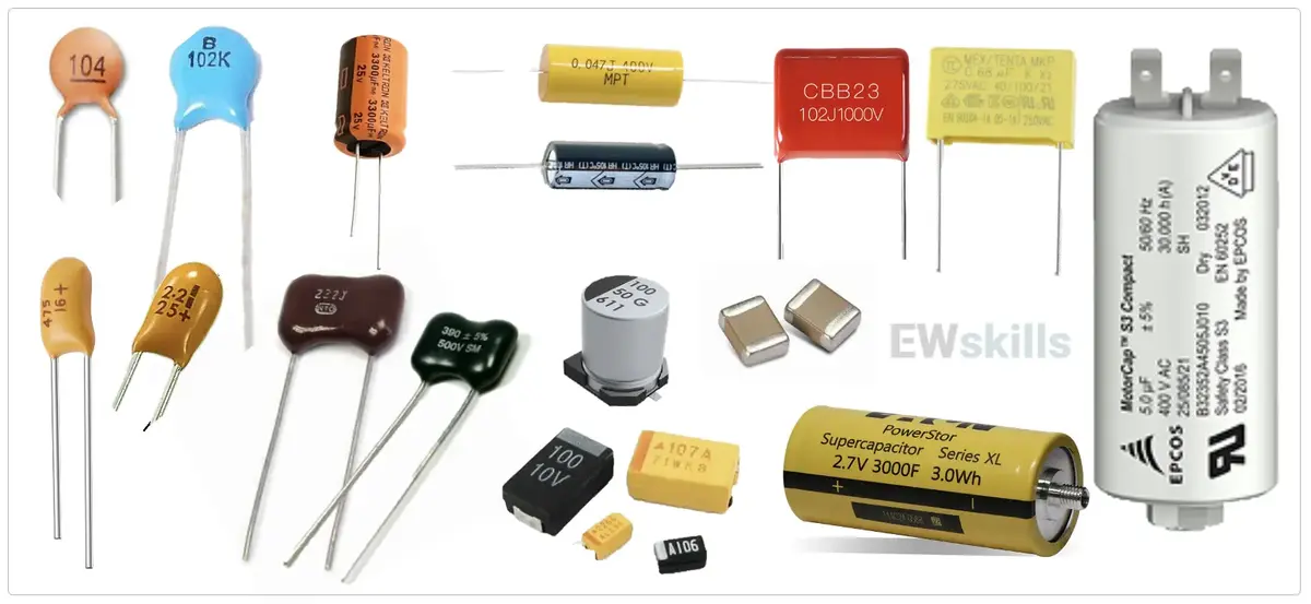
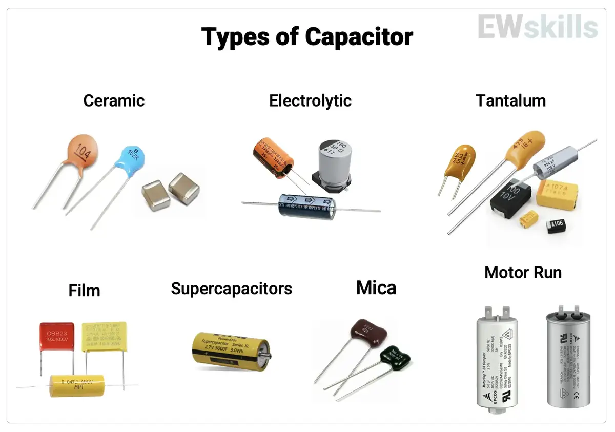
Types of Capacitors
| Type | Capacitance Range | Features | Use Cases |
|---|---|---|---|
| Ceramic (MLCC) | pF to 100μF | Low ESR, compact, non-polarized | Decoupling, filtering |
| Electrolytic | 0.1μF to >10,000μF | High capacitance, polarized, bulky | Power filtering, bulk storage |
| Tantalum | 0.1μF to 1000μF | Stable, small, polarized | Embedded power rails |
| Film (Polyester, etc.) | nF to μF | Stable, non-polarized, low loss | Signal filtering, audio, precision |
| Supercapacitors | Farads | Huge energy storage, low voltage | Backup power, RTC, memory hold-up |
| Mica | pF to nF | Very stable, high accuracy | RF circuits, timing |
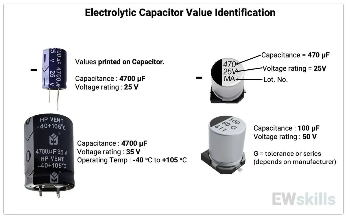
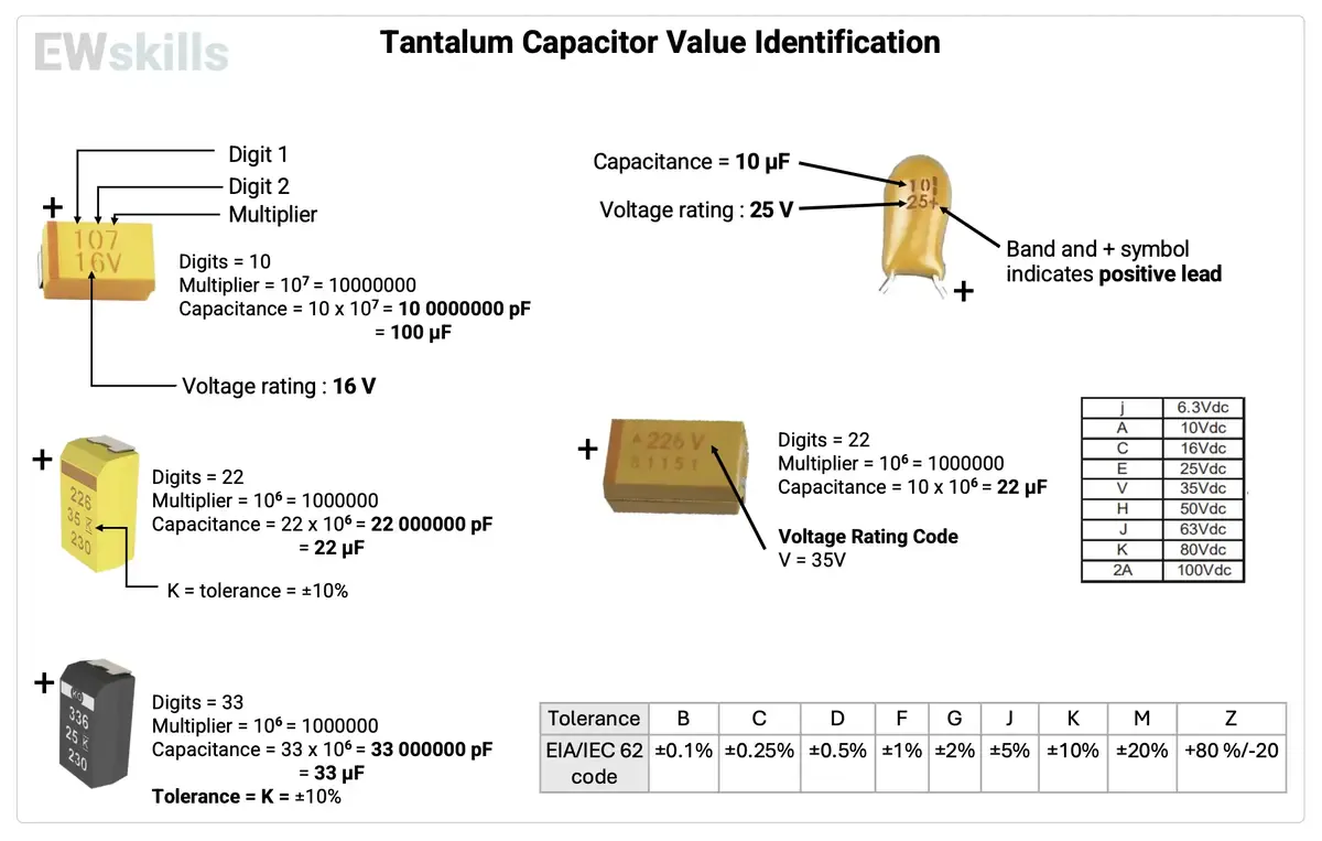
Value identification
Usually, we see capacitors rated in the pico to microfarad range.
| Prefix Name | Abbreviation | Weight | Equivalent Farads |
|---|---|---|---|
| Picofarad | pF | 10^-12 | 0.000000000001 F |
| Nanofarad | nF | 10^-9 | 0.000000001 F |
| Microfarad | µF | 10^-6 | 0.000001 F |
| Milifarad | mF | 10^-3 | 0.001 F |
| Kilofarad | kF | 10^3 | 1000 F |
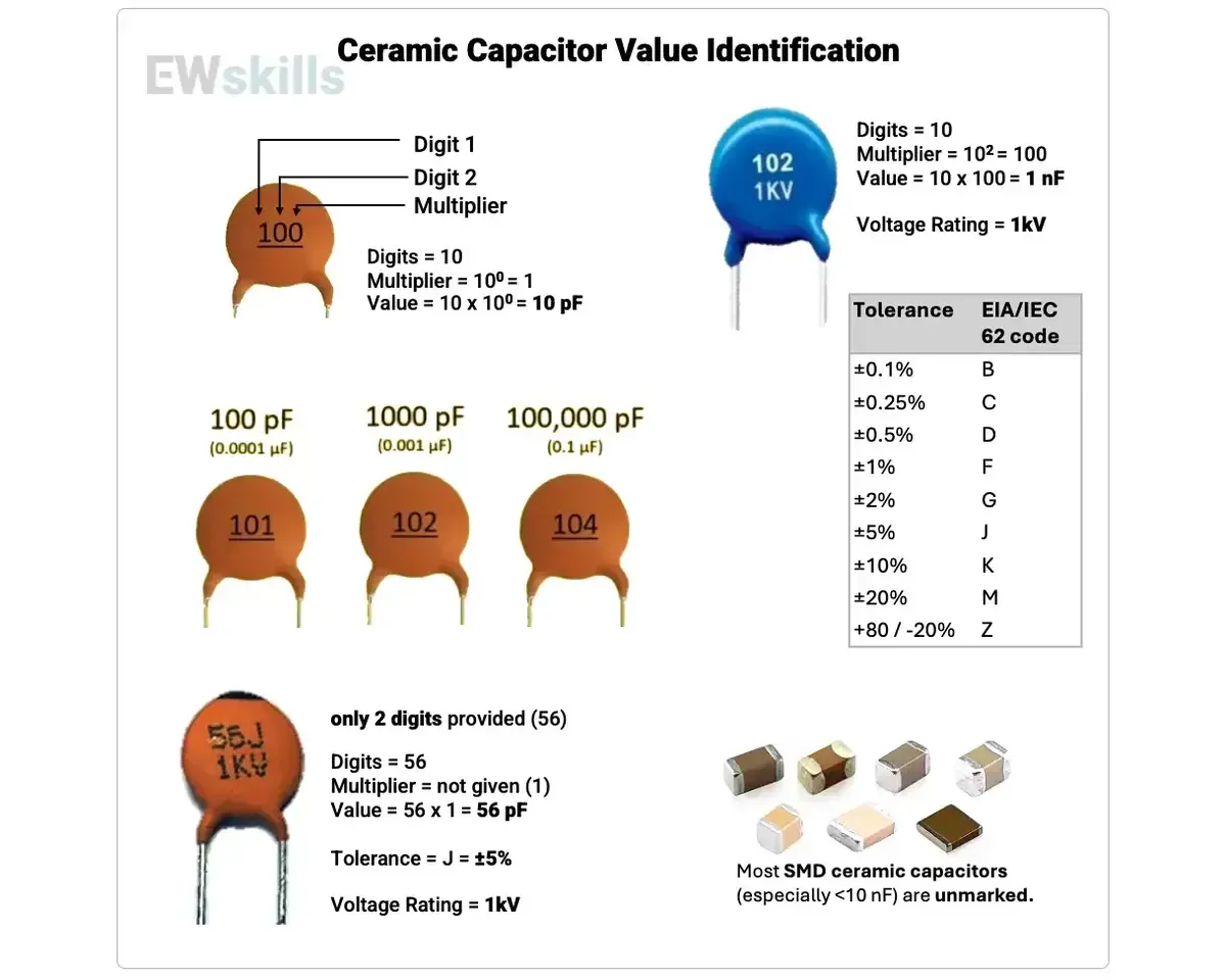
Note: Many very small ceramic SMD capacitors (like 0402) do not have any markings due to space constraints. In such cases, refer to the BOM or multimeter (LCR meter).
Capacitor Terminal Identification:
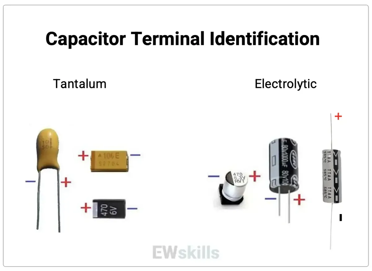
Axial Capacitor’s arrow indicator for -ve Terminal.
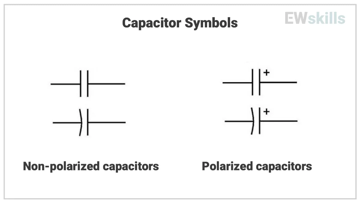
Capacitor PCB Symbol
Capacitor Key Specifications
- Capacitance: Measured in Farads; practical values range from 1pF to several thousand μF
- Rated Voltage: The maximum DC voltage the capacitor can withstand.
Derate by 50–80% for reliability (e.g., use 16V cap on 5V rail) - Tolerance: How much actual capacitance can vary from the nominal value (e.g., ±5%, ±10%, ±20%)
- Dielectric Type: Affects temperature stability, tolerance, aging, and linearity. Example: X7R (good stability), Y5V (poor stability), C0G/NPO (very stable)
- Equivalent Series Resistance (ESR): Represents internal resistance. Low ESR is essential for power decoupling and SMPS circuits.
- Leakage Current: Tiny current that flows through the capacitor; higher in electrolytic/tantalum than in ceramic.
- ESL (Equivalent Series Inductance): Important for high-frequency applications; lower is better.
- Temperature Coefficient: Affects how capacitance changes with temperature (critical in timing and analog applications)
Dissipation Factor (DF or tan δ): It indicates energy loss in a capacitor as heat. Expressed as a decimal or percentage (e.g., 0.02 or 2%). Lower DF means better efficiency, typically <0.1 for ceramics and <0.2 for electrolytics.
Defined as:
DF = ESR / Xc = tan(δ) (where ESR is Equivalent Series Resistance, Xc is capacitive reactance.) - Ripple Current: The maximum AC current a capacitor can handle continuously without overheating. Important for filtering applications (e.g., in power supplies). Exceeding this value reduces capacitor life due to internal heating.
- Load Life (Endurance): Defined as the time the capacitor can operate at rated voltage and maximum temperature without significant degradation. Commonly specified like: “1000 hours @ 105°C, rated voltage”.
After this time, parameters like capacitance, ESR, and leakage current must remain within specified limits.
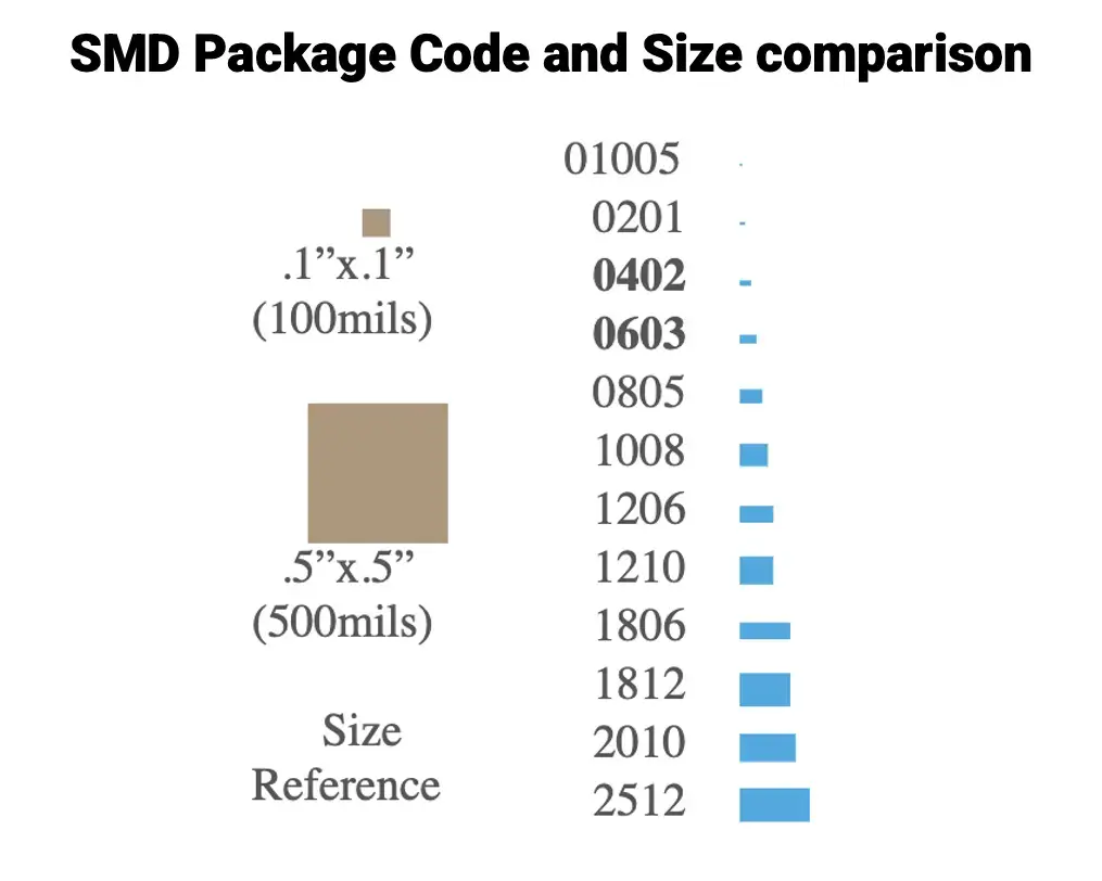
Capacitor Packages and Footprints
Surface Mount (SMD) Packages
| Package | Dimensions (mm) | Voltage Range | Common Use |
|---|---|---|---|
| 0402 | 1.0 × 0.5 | Up to 50V | Bypass, signal filters |
| 0603 | 1.6 × 0.8 | Up to 100V | Decoupling, signal |
| 0805 | 2.0 × 1.25 | Up to 100V | General purpose |
| 1206 | 3.2 × 1.6 | Up to 100V | Power rails |
| 1210+ | 3.2 × 2.5+ | Up to 250V | Bulk decoupling, filtering |
- Ceramic SMD capacitors come in multilayer (MLCC) form.
- Tantalum and electrolytic are also available in SMD (e.g., Case A, B, C sizes).
Through-Hole Capacitors
- Radial Electrolytic: Cylindrical, often for high-cap bulk filtering
- Axial Film Capacitors: Used in high-reliability or high-voltage circuits
Capacitor Selection: Practical Guidelines
| Parameter | Recommendation |
|---|---|
| Voltage Rating | Choose ≥2× of the actual applied voltage |
| Temperature Stability | Use C0G/NPO for timing, X7R for general decoupling |
| ESR | Low ESR ceramic (X7R) or aluminum polymer for power circuits |
| Tolerance | Use ±1–5% in precision analog, ±10–20% for general decoupling |
1. Ceramic Capacitors
- Dielectric affects stability and capacitance drift
Stable types: NP0/C0G (best for timing), X7R (good general purpose)
2. Electrolytic Capacitors (Aluminum)
- Observe polarity; a reverse connection can cause bulging/popping
- Check the ripple current rating and ESR for the power supply used
3. Tantalum Capacitors
- Have Lower ESR, good for regulated power rails
- Strictly stay within voltage limits
- Sensitive to surge/inrush current → Use a series resistor if needed
- Avoid in high-noise or high-current paths
4. Film Capacitors (Polyester, Polypropylene, etc.)
- Have excellent stability, low loss
- Bulky size; not ideal for tight PCB spaces
- Choose polypropylene for high precision/timing, and polyester for general use
5. Supercapacitors (Ultracapacitors)
- Slow response; not suitable for high-frequency circuits
- Usually low voltage (~2.5V) → series balancing may be needed
- Leakage current and ESR must be considered
6. Mica Capacitors
- Very stable and low-loss
- More expensive and larger than ceramics for similar ratings
- Mostly for niche RF or military applications
Capacitor Aging and Behavior
- Ceramic capacitors with Class II and III dielectrics (X7R, Y5V) degrade over time
- Electrolytics: uses liquid or gel electrolyte, which dry out over time → increased ESR, reduced capacitance. Datasheets specify life in hours (e.g., 2000h @ 105°C). Actual life increases if used at lower temperatures:
Rule of thumb: For every 10°C drop below the rated temperature, life doubles. (Arrhenius law)
So, a 2000h cap rated for 105°C can last ~8000h at 85°C.
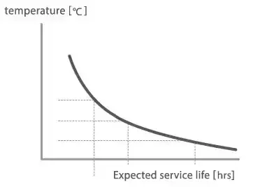
We can observe in the graph, as the temperature decreases, the life expectancy of the capacitor increases.
Commonly, the service life of an aluminium electrolytic capacitor is around 10 Years.
Capacitor Damage
- Tantalum capacitor: Damaged if its voltage or current ratings are exceeded.
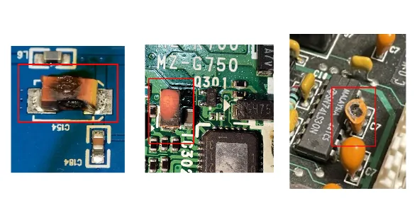
- Electrolytic capacitors: When subjected to overvoltage, reverse polarity, or overheating, they often bulge, leak, or pop, sometimes ejecting their internal materials.
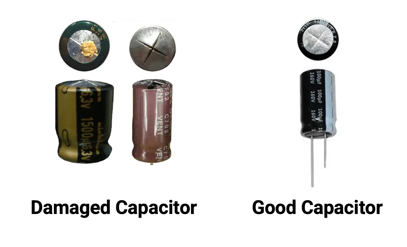
To prevent such failures:
- Always operate capacitors within their voltage and temperature ratings and correct polarity.
- Add series resistors or soft-start circuits to limit inrush current, especially for tantalum capacitors.
- Consider using protection like fuses or current-limiting components when using sensitive capacitors.
Concept understood? Let's apply and learn for real