
42. Code converters and translators
Question.3
A position sensor provides the 4-bit binary value 1011. What is the equivalent Gray code?
A code converter is a combinational circuit that changes one digital representation into another equivalent representation. Its output depends only on the current input, so it does not need a clock or a storage element.
Signal flow: Source code → Gate network → Destination code
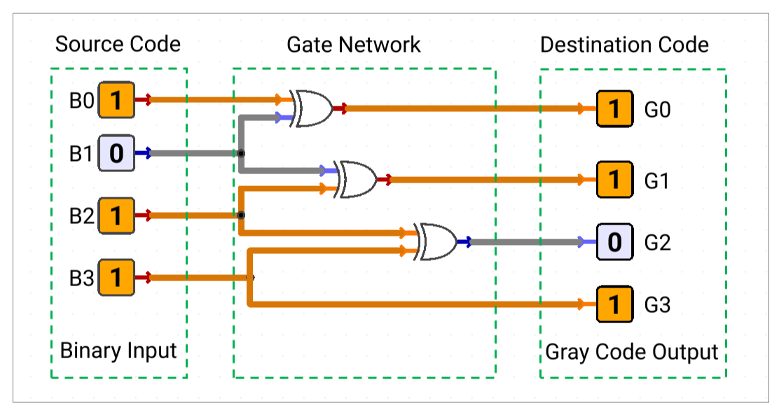
The terms code converter and code translator are commonly used for the same type of circuit: a circuit that maps one set of code words to another.
Common Code Types
Code | Meaning | Important rule | Typical use |
|---|---|---|---|
Binary | A weighted representation using powers of 2 | A 4-bit word can represent 0 to 15 | Arithmetic and digital control |
BCD | Each decimal digit is encoded separately using 4 bits | Only 0000 to 1001 represent decimal digits | Displays and decimal interfaces |
Gray | A code arranged so adjacent values change safely | Consecutive code words differ by one bit | Rotary encoders and position sensors |
Excess-3 | A decimal digit represented after adding 3 to its BCD value | The code is self-complementing | Decimal arithmetic and code translation |
Decimal Digit Code Map
The table shows the commonly used 4-bit code words for one decimal digit.
| Decimal digit | BCD | Gray | Excess-3 |
| 0 | 0000 | 0000 | 0011 |
| 1 | 0001 | 0001 | 0100 |
| 2 | 0010 | 0011 | 0101 |
| 3 | 0011 | 0010 | 0110 |
| 4 | 0100 | 0110 | 0111 |
| 5 | 0101 | 0111 | 1000 |
| 6 | 0110 | 0101 | 1001 |
| 7 | 0111 | 0100 | 1010 |
| 8 | 1000 | 1100 | 1011 |
| 9 | 1001 | 1101 | 1100 |
Valid and Invalid Code Words
BCD uses four bits, but it does not use all sixteen possible combinations. The lower ten combinations represent decimal digits; the remaining combinations are not valid BCD digit codes.
| BCD input | Meaning | Design decision |
| 0000 to 1001 | Valid decimal digits | Produce the required destination code |
| 1010 to 1111 | Invalid BCD combinations | Define an error response, or leave the output unspecified if the system allows it |
When an output is unspecified for an unused input, X may be used as a don't-care value during Boolean simplification. X means either HIGH or LOW; it is not a third logic level and should not be used when the circuit must detect or reject invalid input. If invalid codes matter in the real system, add a validity detector or specify a defined output for every input combination.
Designing a Code Converter
1. Identify the source code and destination code.
2. Label every input and output bit consistently, with the MSB on the left and the LSB on the right.
3. Create a mapping table for all required valid input words.
4. Decide what the circuit must do for unused or invalid input words.
5. Derive one Boolean expression for each output bit using Boolean algebra or K-maps.
6. Simplify the expressions while preserving the required mapping.
7. Implement the expressions with the permitted gates.
8. Verify valid codes, boundary values, and invalid-code behaviour.
The resulting circuit remains combinational:
Input code → Logic equations → Gate network → Output code
Binary-to-Gray Conversion
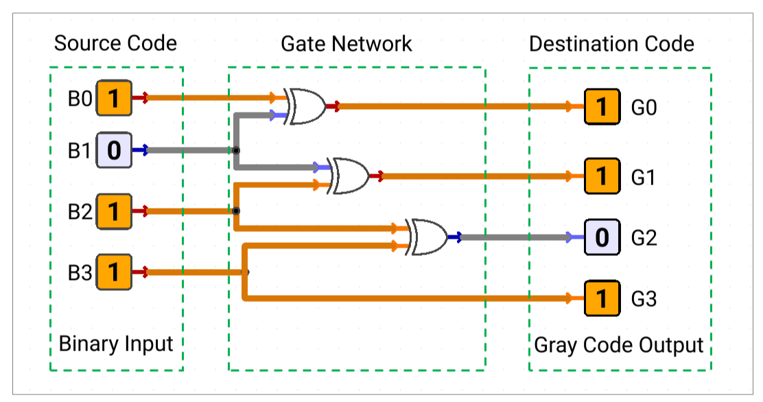
Binary-to-Gray conversion copies the binary MSB. Each following Gray bit is the XOR of two adjacent binary bits.
For a 4-bit input B3 B2 B1 B0:
- G3 = B3
- G2 = B3 ⊕ B2
- G1 = B2 ⊕ B1
- G0 = B1 ⊕ B0
Signal flow: copy the MSB + adjacent XOR gates → Gray output
Why Gray Code Helps
In a normal binary transition, several bits may change at nearly the same time. A receiver can briefly read a mixed value during that transition. Gray code limits consecutive values to one changing bit, reducing this type of transition error in position-sensing systems.
For a BCD-to-Gray converter, the same adjacent-XOR rule can be applied to the valid BCD digit bits. The behaviour of invalid BCD inputs must still be defined separately.
Gray-to-Binary Conversion
Gray-to-binary conversion is cumulative. Copy the Gray MSB, then work from the MSB toward the LSB. Each binary bit is the XOR of the previous binary result and the current Gray bit.
For a 4-bit input G3 G2 G1 G0:
● B3 = G3
● B2 = B3 ⊕ G2
● B1 = B2 ⊕ G1
● B0 = B1 ⊕ G0
Signal flow: Gray MSB → cumulative XOR chain → binary output
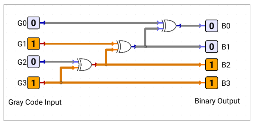
When the Gray input is restricted to the code words assigned to decimal digits, the recovered binary word can be used as the BCD output. Any unassigned Gray input must have a defined or explicitly unspecified result.
BCD-to-Excess-3 Conversion
Excess-3 represents a decimal digit by adding 3 to its BCD value. The conversion can be implemented with a small adder or with an equivalent Boolean gate network.
Signal flow: valid BCD digit → add 0011 → Excess-3 digit
Boolean Equations
- E3 = D3 + D2·(D1 + D0)
- E2 = D2 ⊕ (D1 + D0)
- E1 = D1 XNOR D0
- E0 = ~D0
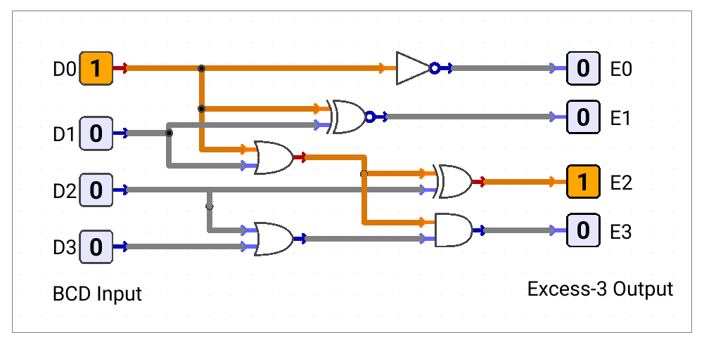
The general relationship is:
● Excess-3 = BCD value + 0011
● BCD value = Excess-3 value − 0011 for valid code words
Self-Complementing Property
Excess-3 is self-complementing. The bitwise complement of the Excess-3 code for a decimal digit represents the Excess-3 code for its 9's complement.
If E(d) denotes the Excess-3 code for digit d, then:
~E(d) = E(9 − d)
This property can simplify some decimal subtraction and arithmetic circuits.
Gate-Level Implementation
If a converter must be built from individual gates, implement each output equation as a separate logic path and share common intermediate signals where useful.
● Generate an inverted signal once and reuse it instead of repeating NOT gates.
● Build AND terms first, then combine alternative terms with OR gates.
● Use named intermediate signals for long expressions.
● If XOR is unavailable, construct it from basic gates:
A ⊕ B = (A·~B) + (~A·B)
● Check the allowed gate types and input count before finalising the circuit.
● Remember that the output follows the current input after propagation delay; no clock, latch, register, or flip-flop is required.
Verification Checklist
| Check | What to verify |
| Bit order | MSB and LSB positions are consistent from input to output |
| Mapping | Every required valid input produces the correct destination code |
| Conversion direction | Binary-to-Gray uses adjacent XOR; Gray-to-binary uses cumulative XOR |
| BCD validity | Unused BCD combinations are rejected or handled according to the specification |
| Gray transitions | Adjacent position values differ by one Gray bit |
| Logic equivalence | The gate network matches the mapping table or Boolean equations |
| Timing | The output changes only after the expected combinational propagation delay |
| Implementation | Only permitted gates and connections are used |
Before testing, choose representative low, middle, and high valid code words. Also test a code near a valid-range boundary and at least one unused input if the specification defines its behaviour.
Applications
| Application | Converter pattern | Purpose |
| Rotary position sensing | Gray → Binary | Recover a numeric position while reducing transition errors |
| Decimal display interface | BCD → display code | Convert a BCD digit into the control pattern required by a decimal display. |
| Digital subsystem interface | One assigned code → another assigned code | Match the format expected by a different circuit block |
| Decimal arithmetic support | BCD ↔ Excess-3 | Use the shifted representation and self-complementing property where suitable |
Quick Summary
● A code converter is a combinational mapping between two digital representations.
● BCD represents one decimal digit per 4-bit group; only ten combinations are valid.
● Binary-to-Gray conversion copies the MSB and XORs adjacent binary bits.
● Gray-to-binary conversion copies the MSB and uses cumulative XOR toward the LSB.
● Excess-3 is formed by adding 0011 to a valid BCD digit.
● Unused input codes may be treated as don't-cares only when their output is genuinely unspecified.
● Always verify the mapping table, bit order, invalid-code behaviour, and gate-level implementation.