
37. K-Map Logic Optimization
Question.6
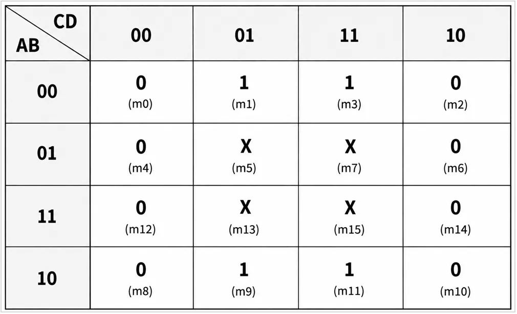
The Boolean function is represented by the 4-variable K-map shown below. Cells marked X are don’t-care conditions.
Which expression is the most simplified form of the function?
Combinational circuits produce outputs only from the present input values. They do not store previous states and normally do not require a clock.
Inputs → Combinational Logic → OutputsCombinational Logic Optimization
The same combinational function can often be represented by different Boolean expressions. Logic optimization finds a simpler equivalent expression, reducing the required gates and logic levels.
Common methods include:
- Boolean algebra: Simplifies expressions using Boolean laws.
- Karnaugh Map (K-map): Groups related input combinations to eliminate unnecessary variables.
- Don’t-care conditions: Uses unused input combinations when they help simplify the function.
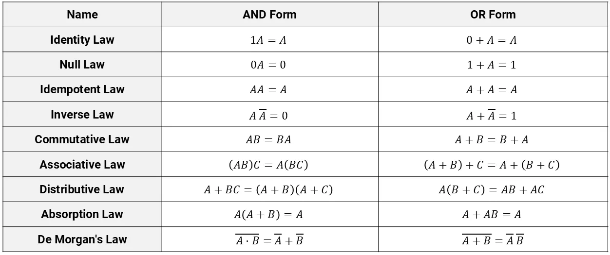
Boolean Algebra Laws and Rules:
SOP and POS Forms
Boolean functions are commonly written in two forms:
| Form | Structure | K-Map Method |
|---|---|---|
| SOP – Sum of Products | Product terms ORed together | Group 1s |
| POS – Product of Sums | Sum terms ANDed together | Group 0s |
SOP: F = A' · C + A · B
POS: F = (A + C) · (A' + B)
In SOP, each product term represents a condition that makes F = 1. In POS, each sum term is derived from a condition where F = 0.
3-Variable K-Map Example
For inputs A, B, and C:
F(A,B,C) = Σm(1,3,6,7)Here, Σm identifies the minterms where F = 1.
In a 3-variable K-map, A selects the row and BC selects the column. The columns follow Gray-code order:
00 → 01 → 11 → 10This ensures that adjacent cells differ in only one variable.
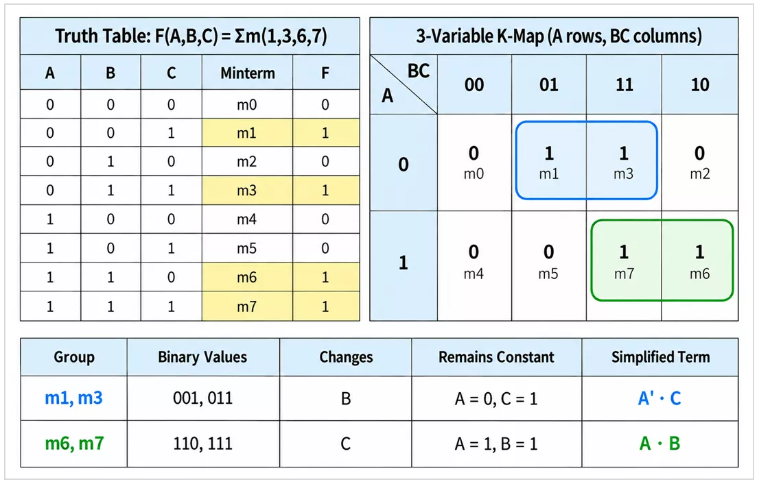
For SOP simplification, adjacent 1s are grouped in the largest possible groups of 1, 2, 4, 8, ... cells. A variable that changes within a group is eliminated; variables that remain constant form the simplified term.
m1, m3 → A' · Cm6, m7 → A · B
Each group is a condition that can make F = 1, so the terms are combined using OR (+):
F = A' · C + A · BPOS from the Same K-Map
For POS simplification, group the cells where F = 0:
F(A,B,C) = ΠM(0,2,4,5)Here, ΠM identifies the maxterms where F = 0.
m0, m2 → (A + C)m4, m5 → (A' + B)
Each group forms a sum term. The sum terms are combined using AND (·):
F = (A + C) · (A' + B)Thus, the same function can be represented as:
SOP: F = A' · C + A · B
POS: F = (A + C) · (A' + B)
Optimized Logic Circuit
The simplified SOP expression can be implemented using logic gates:
F = A' · C + A · B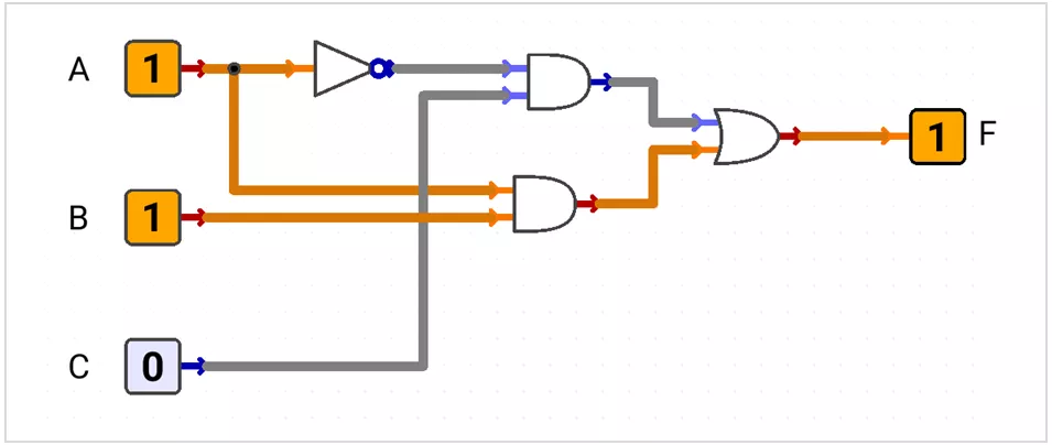
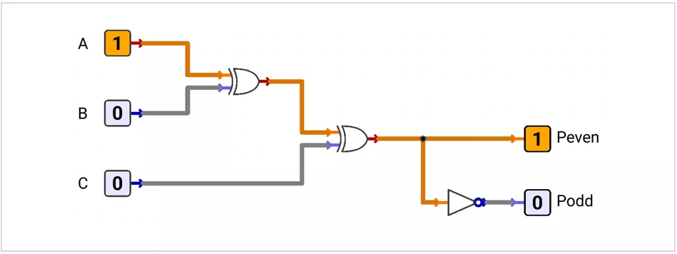
Parity Bit Generator
A parity bit generator generates an extra bit so the total number of 1s becomes either even or odd.
Even Parity
Peven = A ⊕ B ⊕ C
- Even number of data 1s → Peven = 0
- Odd number of data 1s → Peven = 1
Odd Parity
Podd = (A ⊕ B ⊕ C)'
- Even number of data 1s → Podd = 1
- Odd number of data 1s → Podd = 0
Example: ABC = 100
Peven = 1→ total number of 1s = 2 → even parityPodd = 0→ total number of 1s = 1 → odd parity
Encoder
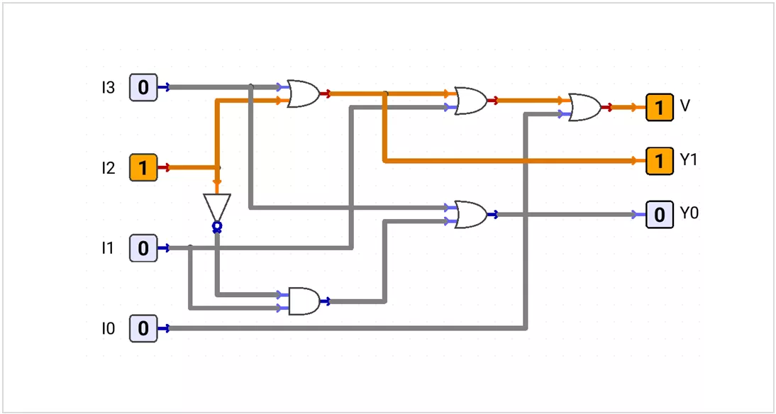
An encoder converts an active input line into a binary code.
A priority encoder encodes only the highest-priority active input.
Priority: I3 > I2 > I1 > I0
| I3 | I2 | I1 | I0 | V | Y1 | Y0 |
|---|---|---|---|---|---|---|
| 0 | 0 | 0 | 0 | 0 | X | X |
| 0 | 0 | 0 | 1 | 1 | 0 | 0 |
| 0 | 0 | 1 | X | 1 | 0 | 1 |
| 0 | 1 | X | X | 1 | 1 | 0 |
| 1 | X | X | X | 1 | 1 | 1 |
V = I3 + I2 + I1 + I0
Y1 = I3 + I2
Y0 = I3 + I2' · I1
In input columns, X means a lower-priority input does not affect the result. When V = 0, Y1_Y0 is invalid and may be treated as don't-care.
Example: 0111 → highest active input = I2 → Y1_Y0 = 10, V = 1
Decoder
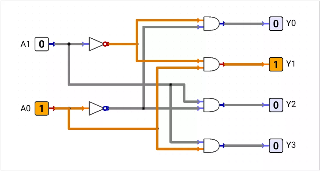
A decoder converts an n-bit input code into one selected output among up to 2ⁿ output lines.
2 input bits → 4 outputs
3 input bits → 8 outputs
2-to-4 Active-HIGH Decoder
| A1 | A0 | Y3 | Y2 | Y1 | Y0 |
|---|---|---|---|---|---|
| 0 | 0 | 0 | 0 | 0 | 1 |
| 0 | 1 | 0 | 0 | 1 | 0 |
| 1 | 0 | 0 | 1 | 0 | 0 |
| 1 | 1 | 1 | 0 | 0 | 0 |
Y0 = A1'·A0'
Y1 = A1'·A0
Y2 = A1·A0'
Y3 = A1·A0Example: A1_A0 = 10 → Y2 = 1
Active-LOW Decoder
An active-LOW decoder selects one output by making it LOW while the other outputs remain HIGH.
Y0 = (A1'·A0')'
Y1 = (A1'·A0)'
Y2 = (A1·A0')'
Y3 = (A1·A0)'
Active-LOW outputs are commonly used for chip-select and control signals.
Multiplexer
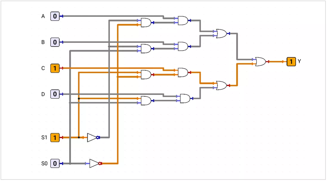
A Multiplexer (MUX) is a data selector. It routes one of several data inputs to one output.
Many Data Inputs → One OutputA 4-to-1 MUX uses data inputs A, B, C, D and select lines S1, S0.
| S1 | S0 | Y |
|---|---|---|
| 0 | 0 | A |
| 0 | 1 | B |
| 1 | 0 | C |
| 1 | 1 | D |
Y = A·S1'·S0' + B·S1'·S0 + C·S1·S0' + D·S1·S0Example: S1_S0 = 10 → Y = C
Demultiplexer
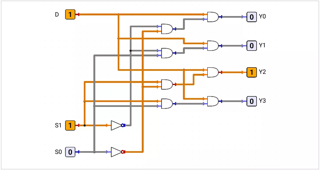
A Demultiplexer (DEMUX) is a data distributor. It routes one input D to one selected output.
One Data Input → One Selected Output| S1 | S0 | Selected Output |
|---|---|---|
| 0 | 0 | Y0 = D |
| 0 | 1 | Y1 = D |
| 1 | 0 | Y2 = D |
| 1 | 1 | Y3 = D |
Y0 = D·S1'·S0'
Y1 = D·S1'·S0
Y2 = D·S1·S0'
Y3 = D·S1·S0Example: S1_S0 = 10 → Y2 = D
Quick Comparison
| Circuit | Signal Flow | Function |
|---|---|---|
| MUX | Many inputs → one output | Select data |
| DEMUX | One input → one selected output | Route data |
| Decoder | Binary code → one selected output | Select output line |
| Priority Encoder | Active inputs → binary code | Encode highest-priority input |
Timing Note: Combinational outputs change after the propagation delay of the logic path.