
79. Synchronous Counters
Question.7
A 3-bit synchronous MOD-5 up counter must count from decimal 0 to 4. Which state table correctly represents the counter?
A digital counter is a sequential circuit that changes through a defined sequence of binary states on each active clock edge.
Asynchronous Counters
In an asynchronous counter, flip-flops do not share one clock.
T_FF_0receives the externalClock.- Each remaining flip-flop receives its clock from the output of the previous flip-flop.
Tis fixed at1, so every active clock edge toggles the stage.
Asynchronous Up Counter
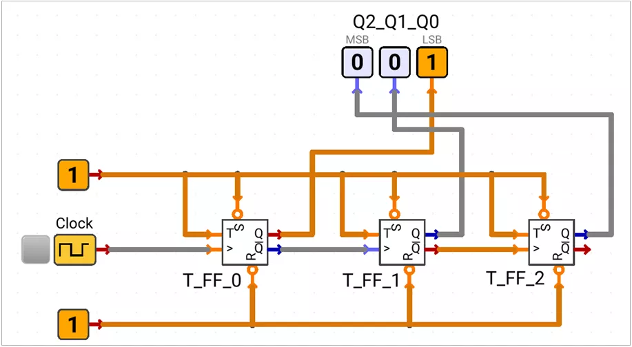
- Circuit uses positive edge triggered flip flops.
T_FF_0toggles from the external clock.- Each higher stage toggles after the previous output changes from
0to1. Q'output is used to clock the next stage.
000 → 001 → 010 → 011 → 100 → 101 → 110 → 111 → 000Asynchronous Down Counter
A 3-bit down counter decreases its state by one. With rising-edge flip-flops, Q clocks the next stage.
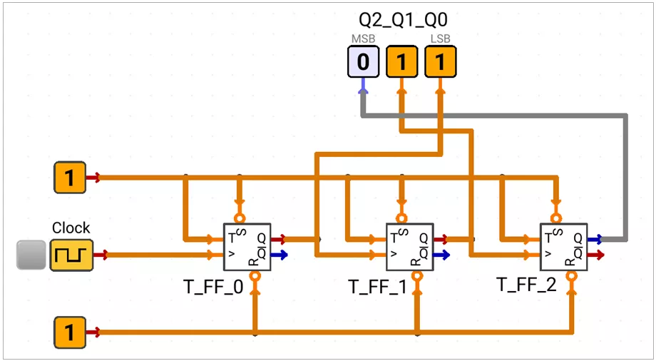
- Circuit uses positive edge triggered flip flops.
T_FF_0toggles from the external clock.- Each higher stage toggles after the previous output changes from
0to1. Qof each stage drives the next clock.
111 → 110 → 101 → 100 → 011 → 010 → 001 → 000 → 111Asynchronous Counter Direction:
Counting direction depends on the flip-flop edge, the output used as the next clock, and the pins used as counter outputs.
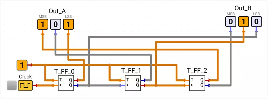
Out_A: 000 → 001 → 010 → 011 → 100 → 101 → 110 → 111 → 000
Out_B: 111 → 110 → 101 → 100 → 011 → 010 → 001 → 000 → 111| Flip-flop trigger | Next flip-flop clock | Counter output pins | Count direction |
|---|---|---|---|
| Rising | Q | Q | Down |
| Rising | Q | Q' | Up |
| Rising | Q' | Q | Up |
| Rising | Q' | Q' | Down |
| Falling | Q | Q | Up |
| Falling | Q | Q' | Down |
| Falling | Q' | Q | Down |
| Falling | Q' | Q' | Up |
Controlled Asynchronous Up-Down Counter
The control signal C selects the clock source of every higher flip-flop.
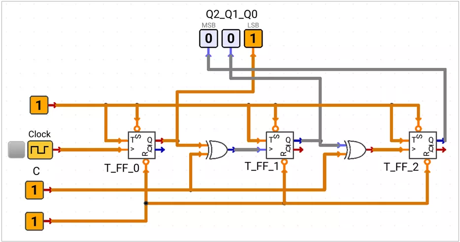
C = 0 | Next Clock = Q ⊕ C = Q | The counter counts down |
|---|---|---|
C = 1 | Next Clock = Q ⊕ C = Q' | The counter counts up |
C = 0: 111 → 110 → 101 → 100 → 011 → 010 → 001 → 000 → 111
C = 1: 000 → 001 → 010 → 011 → 100 → 101 → 110 → 111 → 000
Note: Change C only when counting is disabled and the outputs are stable. Changing it during operation can switch the selected ripple-clock path and create an unwanted clock edge.
Asynchronous MOD Counters:-
A MOD-x counter uses exactly x valid states before repeating.
PRESETandCLEARinputs redirect an unwanted state to the required valid state.- The decoding gate must briefly detect the first unwanted state.
MOD-6 Up counter
A MOD-6 up counter uses states 000 to 101. State 110 is detected and cleared.
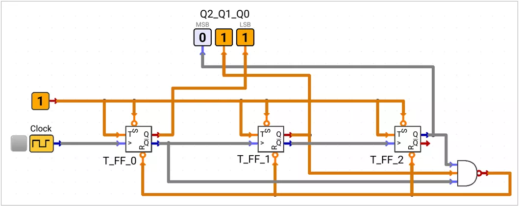
NAND output = (Q₂ · Q₁ · Q₀')'
000 → 001 → 010 → 011 → 100 → 101 → 000
Invalid state recovery
- NAND detection: When
110appears,Q₂ = 1,Q₁ = 1, andQ₀ = 0. The NAND output becomesLOW. - Valid-state return: The active-LOW clear inputs immediately force
000.
Asynchronous Frequency Divider Circuit
A T flip-flop with T = 1 divides its clock frequency by two. Cascaded stages divide it repeatedly.
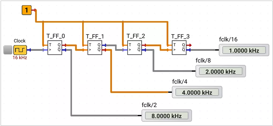
Clock = 16 kHzenters the first stage.Q₀',Q₁',Q₂', andQ₃'give8,4,2, and1 kHzrespectively.- A normal and inverted output have the same frequency.
Output | Frequency |
|---|---|
Q₀ or Q₀' | fCLK / 2 |
Q₁ or Q₁' | fCLK / 4 |
Q₂ or Q₂' | fCLK / 8 |
Q₃ or Q₃' | fCLK / 16 |
fQₖ = fCLK / 2^(k+1), where Q₀ is the first stagePropagation Delay in Asynchronous Counter.
Counter outputs do not change together because every stage waits for the previous stage.
Delay to Qₖ ≈ (k + 1) · tpd
Maximum settling delay for N stages ≈ N · tpd

Where,
k   = flip flop stage index, starting from 0
N   = total number of counter stages
tpd = propagation delay of one flip-flop
(assuming all flip-flops have the same propagation delay)
Effects
- Temporary intermediate counts can appear during a transition.
- Decoded outputs may produce short glitches.
- The maximum safe clock frequency becomes lower.
Synchronous Counters
In a synchronous counter, every flip-flop shares the same clock. All state bits update together at the active edge.
Synchronous Up Counter
000 → 001 → 010 → 011 → 100 → 101 → 110 → 111 → 000Q₂ | Q₁ | Q₀ | Q₂⁺ | Q₁⁺ | Q₀⁺ | T₂ | T₁ | T₀ |
|---|---|---|---|---|---|---|---|---|
0 | 0 | 0 | 0 | 0 | 1 | 0 | 0 | 1 |
0 | 0 | 1 | 0 | 1 | 0 | 0 | 1 | 1 |
0 | 1 | 0 | 0 | 1 | 1 | 0 | 0 | 1 |
0 | 1 | 1 | 1 | 0 | 0 | 1 | 1 | 1 |
1 | 0 | 0 | 1 | 0 | 1 | 0 | 0 | 1 |
1 | 0 | 1 | 1 | 1 | 0 | 0 | 1 | 1 |
1 | 1 | 0 | 1 | 1 | 1 | 0 | 0 | 1 |
1 | 1 | 1 | 0 | 0 | 0 | 1 | 1 | 1 |
T₀ = 1
T₁ = Q₀
T₂ = Q₁ · Q₀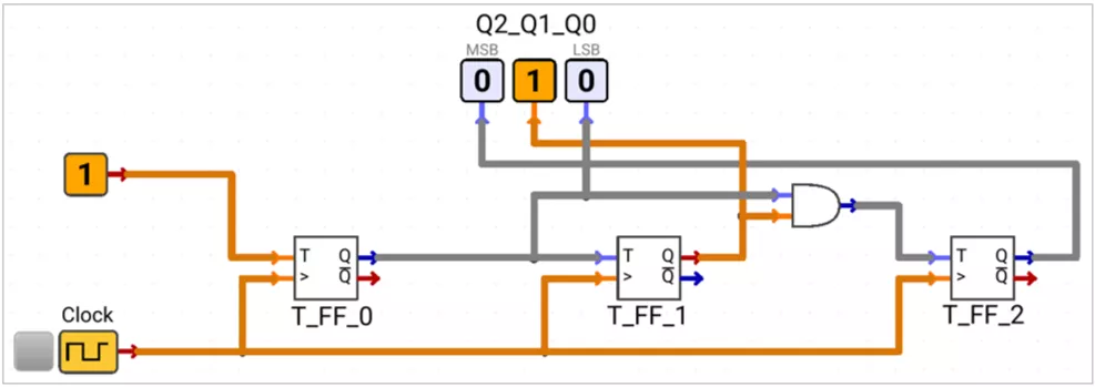
A flip-flop toggles when all its lower-order bits are HIGH.
Synchronous Down Counter
111 → 110 → 101 → 100 → 011 → 010 → 001 → 000 → 111Q₂ | Q₁ | Q₀ | Q₂⁺ | Q₁⁺ | Q₀⁺ | T₂ | T₁ | T₀ |
|---|---|---|---|---|---|---|---|---|
1 | 1 | 1 | 1 | 1 | 0 | 0 | 0 | 1 |
1 | 1 | 0 | 1 | 0 | 1 | 0 | 1 | 1 |
1 | 0 | 1 | 1 | 0 | 0 | 0 | 0 | 1 |
1 | 0 | 0 | 0 | 1 | 1 | 1 | 1 | 1 |
0 | 1 | 1 | 0 | 1 | 0 | 0 | 0 | 1 |
0 | 1 | 0 | 0 | 0 | 1 | 0 | 1 | 1 |
0 | 0 | 1 | 0 | 0 | 0 | 0 | 0 | 1 |
0 | 0 | 0 | 1 | 1 | 1 | 1 | 1 | 1 |
T₀ = 1
T₁ = Q₀'
T₂ = Q₁' · Q₀'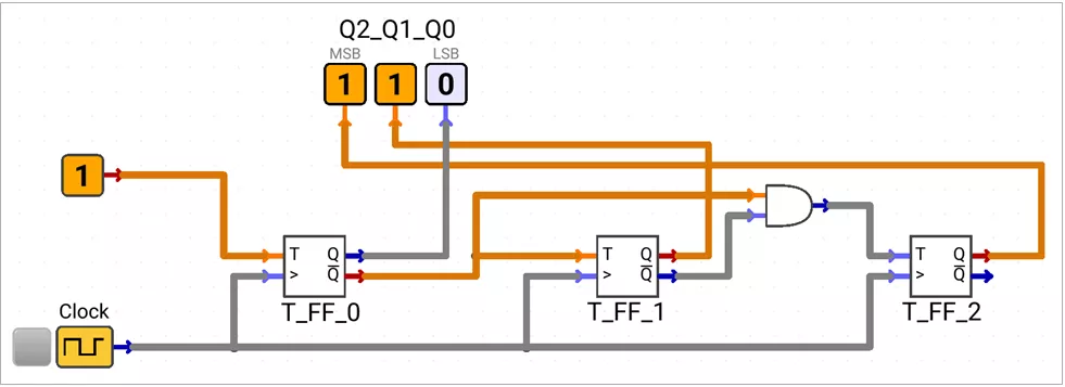
A flip-flop toggles when all its lower-order bits are LOW.
Synchronous Up-Down Counter
C = 0selects down counting.C = 1selects up counting.
C | Q₂ | Q₁ | Q₀ | Q₂⁺ | Q₁⁺ | Q₀⁺ | T₂ | T₁ | T₀ |
|---|---|---|---|---|---|---|---|---|---|
0 | 0 | 0 | 0 | 1 | 1 | 1 | 1 | 1 | 1 |
0 | 0 | 0 | 1 | 0 | 0 | 0 | 0 | 0 | 1 |
0 | 0 | 1 | 0 | 0 | 0 | 1 | 0 | 1 | 1 |
0 | 0 | 1 | 1 | 0 | 1 | 0 | 0 | 0 | 1 |
0 | 1 | 0 | 0 | 0 | 1 | 1 | 1 | 1 | 1 |
0 | 1 | 0 | 1 | 1 | 0 | 0 | 0 | 0 | 1 |
0 | 1 | 1 | 0 | 1 | 0 | 1 | 0 | 1 | 1 |
0 | 1 | 1 | 1 | 1 | 1 | 0 | 0 | 0 | 1 |
1 | 0 | 0 | 0 | 0 | 0 | 1 | 0 | 0 | 1 |
1 | 0 | 0 | 1 | 0 | 1 | 0 | 0 | 1 | 1 |
1 | 0 | 1 | 0 | 0 | 1 | 1 | 0 | 0 | 1 |
1 | 0 | 1 | 1 | 1 | 0 | 0 | 1 | 1 | 1 |
1 | 1 | 0 | 0 | 1 | 0 | 1 | 0 | 0 | 1 |
1 | 1 | 0 | 1 | 1 | 1 | 0 | 0 | 1 | 1 |
1 | 1 | 1 | 0 | 1 | 1 | 1 | 0 | 0 | 1 |
1 | 1 | 1 | 1 | 0 | 0 | 0 | 1 | 1 | 1 |
T₀ = 1
T₁ = Q₀ ⊙ C
T₂ = (Q₀ ⊙ C) · (Q₁ ⊙ C)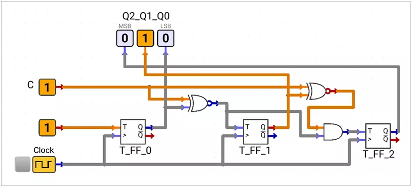
Synchronous MOD counters
A synchronous MOD counter assigns the required next valid state through combinational logic at the flip-flop inputs.
Invalid State Operations
Don't Care method
Invalid-state next values are marked X during logic minimization.
- Advantages:
- Usually produces simpler input equations.
- Uses fewer gates.
- Limitations:
- Recovery from an invalid state is not guaranteed.
- The counter may enter an unintended loop.
X = either HIGH or LOW; the value is chosen only to simplify the logic.
Self-Recovery Method:
Every invalid state is assigned a known valid next state.
- Advantage:
- The counter automatically returns to its valid sequence.
- Startup and fault behavior are predictable.
- Limitation:
- The equations may require more gates.
- Every invalid state must be defined and verified.
MOD-11 Down Counter (counts from 10 to 0)
1010 → 1001 → 1000 → 0111 → 0110 → 0101 → 0100 → 0011 → 0010 → 0001 → 0000 → 1010This example uses self-recovery: every invalid state from 1011 to 1111 returns to 1010.
When ~Reset = 0, the counter asynchronously resets to 1010 and holds this state while Reset remains LOW.
Q₃ | Q₂ | Q₁ | Q₀ | Q₃⁺ | Q₂⁺ | Q₁⁺ | Q₀⁺ | T₃ | T₂ | T₁ | T₀ |
|---|---|---|---|---|---|---|---|---|---|---|---|
1 | 0 | 1 | 0 | 1 | 0 | 0 | 1 | 0 | 0 | 1 | 1 |
1 | 0 | 0 | 1 | 1 | 0 | 0 | 0 | 0 | 0 | 0 | 1 |
1 | 0 | 0 | 0 | 0 | 1 | 1 | 1 | 1 | 1 | 1 | 1 |
0 | 1 | 1 | 1 | 0 | 1 | 1 | 0 | 0 | 0 | 0 | 1 |
0 | 1 | 1 | 0 | 0 | 1 | 0 | 1 | 0 | 0 | 1 | 1 |
0 | 1 | 0 | 1 | 0 | 1 | 0 | 0 | 0 | 0 | 0 | 1 |
0 | 1 | 0 | 0 | 0 | 0 | 1 | 1 | 0 | 1 | 1 | 1 |
0 | 0 | 1 | 1 | 0 | 0 | 1 | 0 | 0 | 0 | 0 | 1 |
0 | 0 | 1 | 0 | 0 | 0 | 0 | 1 | 0 | 0 | 1 | 1 |
0 | 0 | 0 | 1 | 0 | 0 | 0 | 0 | 0 | 0 | 0 | 1 |
0 | 0 | 0 | 0 | 1 | 0 | 1 | 0 | 1 | 0 | 1 | 0 |
1 | 0 | 1 | 1 | 1 | 0 | 1 | 0 | 0 | 0 | 0 | 1 |
1 | 1 | 0 | 0 | 1 | 0 | 1 | 0 | 0 | 1 | 1 | 0 |
1 | 1 | 0 | 1 | 1 | 0 | 1 | 0 | 0 | 1 | 1 | 1 |
1 | 1 | 1 | 0 | 1 | 0 | 1 | 0 | 0 | 1 | 0 | 0 |
1 | 1 | 1 | 1 | 1 | 0 | 1 | 0 | 0 | 1 | 0 | 1 |
T₃ = Q₂' · Q₁' · Q₀'
T₂ = (Q₂ + Q₃) · Q₁' · Q₀' + Q₃ · Q₂
T₁ = Q₃ · Q₂ · Q₁' + (Q₃' + Q₂') · Q₀'
T₀ = Q₀ + Q₂' · Q₁ + (Q₂ ⊕ Q₃)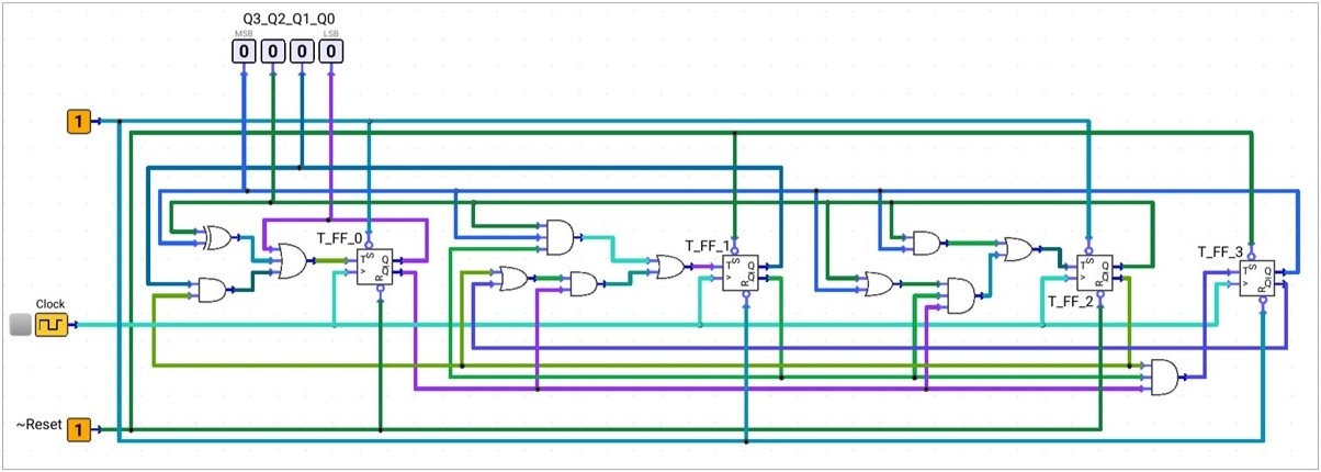
Synchronous Frequency Divider Circuit
A synchronous binary up counter can be used directly as a frequency divider.

T₀ = 1
T₁ = Q₀
T₂ = Q₁ · Q₀
T₃ = Q₂ · Q₁ · Q₀
T₄ = Q₃ · Q₂ · Q₁ · Q₀
T₅ = Q₄ · Q₃ · Q₂ · Q₁ · Q₀
Output | Frequency |
|---|---|
Q0 or Q0' | fCLK / 2 |
Q1 or Q1' | fCLK / 4 |
Q2 or Q2' | fCLK / 8 |
Q3 or Q3' | fCLK / 16 |
Q4 or Q4' | fCLK / 32 |
Q5 or Q5' | fCLK / 64 |
Propagation Delay in Synchronous Circuits
All flip-flops update together, but the next clock edge must wait for the flip-flop and input logic delays.
TCLK(min) ≥ tCQ(max) + tlogic(max) + tsetup

where:
TCLK(min)  = minimum allowable clock period
tCQ(max)   = maximum clock-to-Q delay of a flip-flop
tlogic(max)= maximum propagation delay through the combinational logic
tsetup     = setup-time requirement of the receiving flip-flop
Therefore, fCLK(max) ≤ 1 / TCLK(min).
Custom Sequence Generator
A custom sequence generator is a counter that follows a user-defined state order.
000 → 110 → 010 → 101 → 111 → 100 → 011 → 001 → 000Define the required next state for each current state, then use the T flip-flop excitation relation to determine each T input.
When ~Reset = 0, the counter will asynchronously reset to 000 and holds the value
Q₂ | Q₁ | Q₀ | Q₂⁺ | Q₁⁺ | Q₀⁺ | T₂ | T₁ | T₀ |
|---|---|---|---|---|---|---|---|---|
0 | 0 | 0 | 1 | 1 | 0 | 1 | 1 | 0 |
1 | 1 | 0 | 0 | 1 | 0 | 1 | 0 | 0 |
0 | 1 | 0 | 1 | 0 | 1 | 1 | 1 | 1 |
1 | 0 | 1 | 1 | 1 | 1 | 0 | 1 | 0 |
1 | 1 | 1 | 1 | 0 | 0 | 0 | 1 | 1 |
1 | 0 | 0 | 0 | 1 | 1 | 1 | 1 | 1 |
0 | 1 | 1 | 0 | 0 | 1 | 0 | 1 | 0 |
0 | 0 | 1 | 0 | 0 | 0 | 0 | 0 | 1 |
T₂ = Q₀'
T₁ = (Q₂ ⊙ Q₀) + (Q₂ ⊕ Q₁)
T₀ = Q₂ ⊕ Q₁ ⊕ Q₀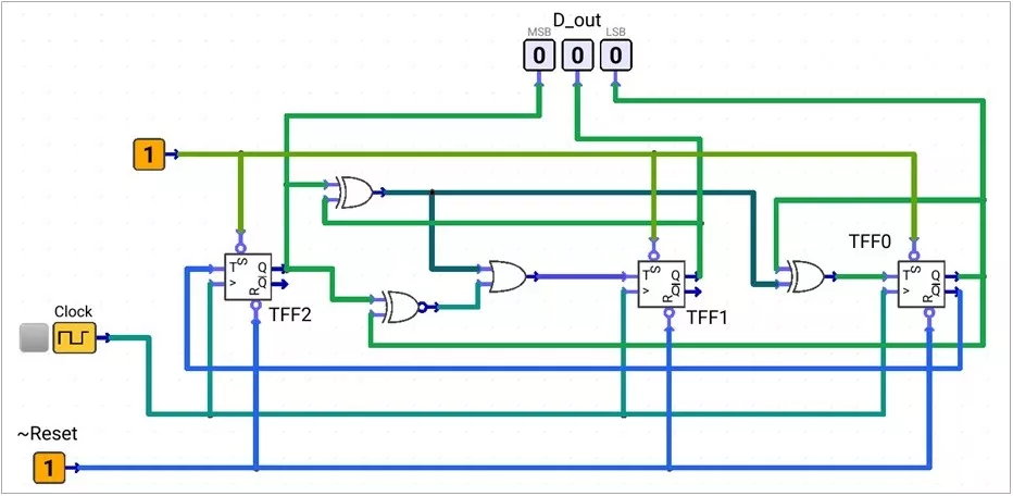
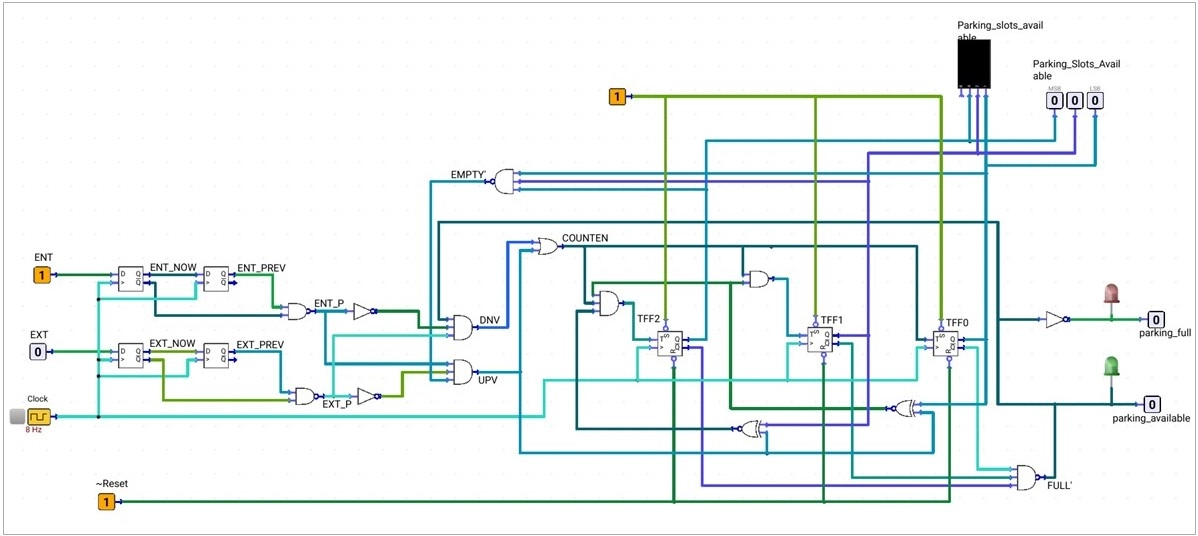
Counter Application - Synchronous Parking Slot Counter
A 3-bit counter stores the number of available parking slots from 0 to 7.
Sensor edge detection
Active-LOW sensors ENT and EXT use falling-edge detectors. Each detector stores the current and previous samples.
ENT_P = (ENT_NOW' · ENT_PREV)'
EXT_P = (EXT_NOW' · EXT_PREV)'
ENT_P = 0for one event when a vehicle enters.EXT_P = 0for one event when a vehicle exits.- At all other times, both pulse outputs remain HIGH.
Boundary Logic
The output bits Q₂, Q₁, and Q₀ detect the two count limits.
FULL = Q₂' · Q₁' · Q₀'
EMPTY = Q₂ · Q₁ · Q₀
FULL = 1at000: no slot is available.EMPTY = 1at111: all seven slots are available.
Reset Logic
When ~Reset = 0, the counter asynchronously resets to 000 and holds this state while Reset remains LOW.
Valid Direction Logic (UPV and DNV)
A single valid sensor pulse creates one active-HIGH direction request. Boundary flags block overflow and underflow.
UPV = EXT_P' · ENT_P · EMPTY'
DNV = ENT_P' · EXT_P · FULL'
UPV = 1: An exit pulse increments the available-slot count whenEMPTY = 0.DNV = 1: An entry pulse decrements the count whenFULL = 0.
ENT_P | EXT_P | FULL | EMPTY | UPV | DNV | Operation |
|---|---|---|---|---|---|---|
1 | 1 | X | X | 0 | 0 | Hold: no pulse |
0 | 0 | X | X | 0 | 0 | Hold: simultaneous pulses |
0 | 1 | 1 | X | 0 | 0 | Hold: lower limit reached |
0 | 1 | 0 | X | 0 | 1 | Decrement |
1 | 0 | X | 1 | 0 | 0 | Hold: upper limit reached |
1 | 0 | X | 0 | 1 | 0 | Increment |
Counter Enable and T input Logic:
COUNTEN becomes HIGH only for one valid increment or decrement request.
COUNTEN = UPV + DNV
T₀ = COUNTEN
T₁ = COUNTEN · (Q₀ ⊙ UPV)
T₂ = COUNTEN · (Q₀ ⊙ UPV) · (Q₁ ⊙ UPV) = T₁ · (Q₁ ⊙ UPV)
If COUNTEN = 0, every T input is LOW and the count holds.
Parking LED Flag Logic
The active-HIGH LEDs show whether at least one slot is available.
GREEN = FULL'
RED = GREEN' = FULL
RED = 1only when the count is000.GREEN = 1for counts001to111.