
61. Short Pulse Detection
Design a task using a microcontroller with the following requirements
- Detect a pulse generated by a pulse generator with a duration of approximately 100 ns or less.
- Upon detecting the pulse, toggle the LED.
- No pulses should be missed, and the LED state must be updated immediately
Note: We can generate pulses using any microcontroller.
Also, consider the following condition
- An important task is continuously running in a void loop(). It needs to be executed continuously and cannot be altered or changed.
Your void loop() should be as given below.
void loop() {
  	while (true){
		 //In this loop Microcontroller is busy in monitoring and performing   important tasks constantly.
}
}
For example:
Code for pulse generation using Arduino UNO.
- The code generates a pulse of width 64 nanoseconds every 5000 ms.
- The pulse is generated on digital pin no. 7 of Arduino UNO.
void setup() {
  Serial.begin(115200);        // Initialize serial communication at 115200 baud rate
  pinMode(7, OUTPUT);          // Set pin 7 as an output pin
  digitalWrite(7, LOW);        // Set pin 7 to LOW (initial state)
}

void loop() {
  PORTD = 0x80;                // Set the 7th bit of PORTD to HIGH (binary 10000000), turning on pin 7
  PORTD = 0x00;                // Set all bits of PORTD to LOW (binary 00000000), turning off pin 7
  Serial.println("Pulse Generated");  // Print "Pulse Generated" to the Serial Monitor
  delay(5000);                 // Wait for 5000 milliseconds (5 seconds) before repeating the process
}
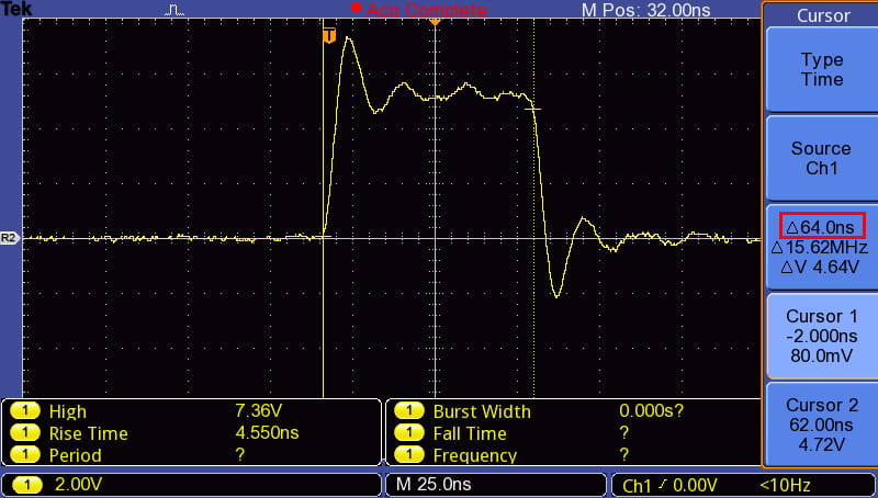
Generated output pulse:
The pulse below is generated by the Pulse Generator after every 5 seconds.
The width of the pulse is around 64 nanoseconds.
Interrupts?

Signal that pauses the main program to handle a specific event, then resumes execution from where it stopped.
Why do we need it?
Interrupts allow a microcontroller to respond quickly to important or time-sensitive events without being stuck in checking for them, making programs faster and more efficient.
Common Interrupt Sources in Microcontrollers:
- Timer Interrupts – Triggered when a timer overflows or matches a preset value.
- External Interrupts – Generated by external events on specific input pins (e.g., button press).
- UART/Serial Interrupts – Occur when data is received or ready to be sent via serial communication.
- ADC Interrupts – Triggered when an analog-to-digital conversion is complete.
- I2C/SPI Interrupts – Generated during data transfer events in communication protocols.
Interrupt Service Routine (ISR)
An Interrupt Service Routine (ISR) is a special function that runs automatically when an interrupt occurs, handling the event and then returning control to the main program.
Best practices for writing ISRs in microcontrollers:
- Keep it short and fast – Avoid delays and heavy processing to return quickly to the main program.
- Avoid using functions like
printf()– These are slow and not safe in ISRs. - Use volatile variables – Share data between ISR and main code using
volatileto prevent compiler optimizations. - Minimize global variables – Use as few global variables as possible to reduce bugs and side effects.
ISR Syntax for different Architectures:
- PIC (XC8)
- Syntax:
void _ _interrupt() ISR(void) - Example:
void _ _interrupt() ISR(void) { /* code */ }
- Syntax:
- AVR (GCC)
- Syntax:
ISR(VECTOR_NAME) - Example:
ISR(TIMER1_COMPA_vect) { /* code */ }
- Syntax:
- ARM (CMSIS)
- Syntax:
void Handler_Name(void) - Example:
void TIM2_IRQHandler(void) { /* code */ }
- Syntax:
Interrupt Vector Table (IVT)
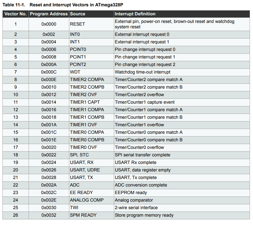
The Interrupt Vector Table (IVT) is a special memory table in microcontrollers that contains the addresses of Interrupt Service Routines (ISRs). When an interrupt occurs, the microcontroller looks up this table to determine the correct ISR to execute.
- Each interrupt source (e.g., Timer, ADC, External Interrupt) is assigned a unique vector number.
- The IVT maps these vector numbers to the memory address of the corresponding ISR.
- Interrupt priority decides which interrupt the microcontroller handles first when many interrupts happen at the same time. Usually, the interrupt with the lower vector number gets handled before the others.
For example, the IVT of ATmega328P:
How a controller handles Interrupts
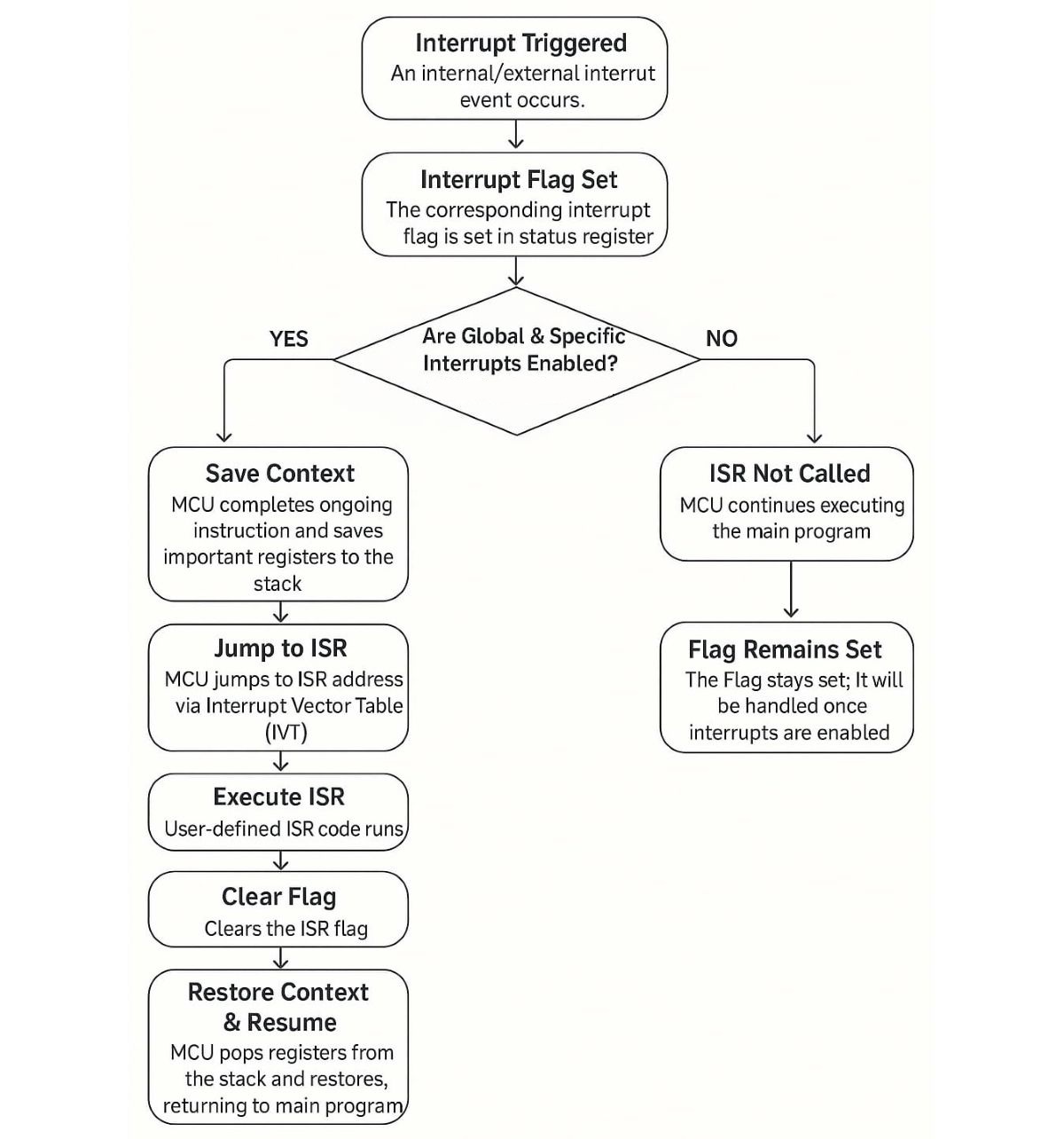
The Controller checks for an interrupt after each machine cycle. If an interrupt occurs, it is handled as follows
Interrupt Nesting
Interrupt nesting is when a microcontroller allows a higher-priority interrupt to interrupt a currently running ISR. This ensures critical tasks are handled quickly, even during another ISR is execution.
Understanding Nested Interrupts on Arduino UNO
In the Arduino UNO, global interrupts are disabled automatically at the start of any ISR to avoid nested execution.
However, if your application needs to handle more urgent interrupts during an ongoing ISR, you can call sei() within the ISR. This manually re-enables global interrupts and allows other interrupts to be nested inside.
Example Code (Enabling Nested Interrupts)
ISR(TIMER0_OVF_vect) {
  // By default, interrupts are disabled inside ISR
  sei();  // Re-enable global interrupts (allows nested interrupts)

  // ISR logic here
}
With this, any other interrupt will get served inside the ISR, irrespective of its priority
Interrupt race condition
In microcontrollers, an interrupt race condition occurs when both the main program and an ISR access or modify a shared resource (such as a global variable) without proper coordination.
This can cause unexpected results due to overlapping or incomplete operations.
Without using techniques like disabling interrupts temporarily or declaring the variable as volatile, the program may behave unpredictably.
Consider the following Arduino UNO example where a shared variable counter is modified by both the main code and a timer overflow ISR:
volatile uint8_t counter = 0;

void ISR_TIMER0_OVF_vect(void) {
  counter++;  // Interrupt modifies counter
}

int main() {
  cli();  // Disable global interrupts
  if (counter > 0) {
    counter--;  // Main code modifies the same counter
  }
  sei();  // Enable global interrupts
}
Explanation:
volatileensures correct access to thecountervariable.cli()/sei()create a critical section, preventing the ISR from interrupting the main code during access.- This prevents a race condition and ensures data consistency.
What is Atomicity?
Some code must run without interruption to avoid errors or data corruption. To protect it, interrupts are turned off before the critical part and turned back on after.
Interrupt latency
Interrupt latency is the time delay between when an interrupt occurs and when the ISR starts executing.
It depends on factors like current instruction execution, interrupt priority, and system overhead. Lower latency allows faster response to real-time events.
In ATmega328P, the typical latency is around 4–5 clock cycles after an interrupt is enabled and a signal is received. (~250–312.5 ns at 16 MHz).
Interrupt Registers
In AVR microcontrollers, each peripheral (like Timer, ADC, UART) uses key interrupt registers:
- Interrupt Enable Register (IER): Enables specific interrupts.
Example:TIMSKenables timer interrupts;UCSRBenables UART interrupts. - Interrupt Flag Register (IFR): Shows which interrupts are pending via flags set automatically when events occur.
Example:TIFRholds timer interrupt flags (like overflow). Flags clear automatically when the ISR runs or by writing ‘1’. - Interrupt Configuration Register (ICR): Sets interrupt triggering modes (edge/level).
Example:EICRAconfigures edge triggering for external interrupts INT0 and INT1.
Some peripherals use other control registers (e.g.,ADCSRAfor ADC).
Global interrupts must be enabled via the GIE bit in SREG (using the SEI instruction).
AVR interrupt priorities are fixed by the vector table order.
For other microcontrollers (e.g., ARM Cortex-M):
Interrupt enabling, flag status, and configuration are similar but often managed by separate peripheral registers plus a central interrupt controller (like NVIC), which handles priorities and masking more flexibly.
Interrupt Driver
Generic Interrupt Setup Flow (Microcontroller)
- Identify the Interrupt Source
Choose what should trigger the interrupt (e.g., timer overflow, GPIO pin change, UART receive, ADC complete, etc.).
- Configure the Peripheral (if needed)
Set up the related hardware module (e.g., configure timer, UART, GPIO pin mode, etc.) so it can generate an interrupt when needed.
- Enable Interrupt in Peripheral
Use the specific register (likeTIMx_DIER,UARTx_CR1, orEXTI_IMR) to enable the interrupt generation for that peripheral.
Few controllers have additional steps like “Set Interrupt Priority” and “NVIC enable” as given below.Set Interrupt Priority (Optional but Recommended)
If supported by the MCU (e.g., ARM Cortex-M), assign a priority using NVIC (Nested Vectored Interrupt Controller) functions/registers.Enable Interrupt in NVIC (if applicable)
Turn on the interrupt at the global controller level (e.g., usingNVIC_EnableIRQ()for ARM Cortex-M devices).
- Write the Interrupt Service Routine (ISR)
Create a function with the correct name or vector address — it will execute automatically when the interrupt occurs. - Clear the Interrupt Flag
Inside the ISR, clear the interrupt flag (manually for most MCUs) to avoid repeated triggers. - Enable Global Interrupts (if disabled)
Use instruction or register to enable global interrupt handling (e.g., sei() in AVR,__enable_irq()in ARM).
Examples
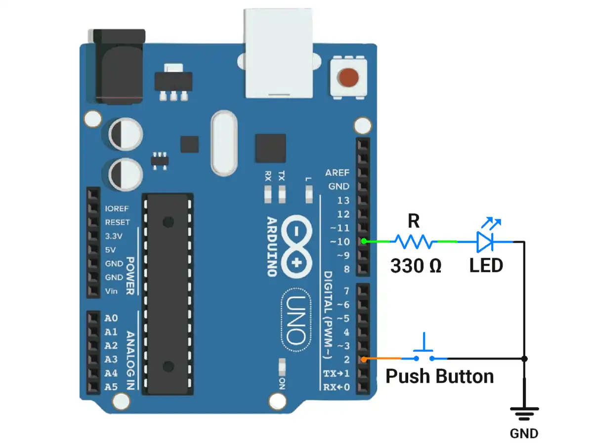
1.Arduino UNO example for LED toggling on switch press using an interrupt.
Code
volatile bool ledState = false;  // Shared between ISR and main
void setup() {
  pinMode(10, OUTPUT);           // LED pin
  pinMode(2, INPUT_PULLUP);      // INT0 pin with internal pull-up

  attachInterrupt(digitalPinToInterrupt(2), toggleLED, FALLING);  // Interrupt on falling edge
}
void loop() {
  // Nothing here; LED toggling handled by ISR
}

void toggleLED() {
  ledState = !ledState;          // Toggle state
  digitalWrite(10, ledState);    // Reflect the new state on the LED
}
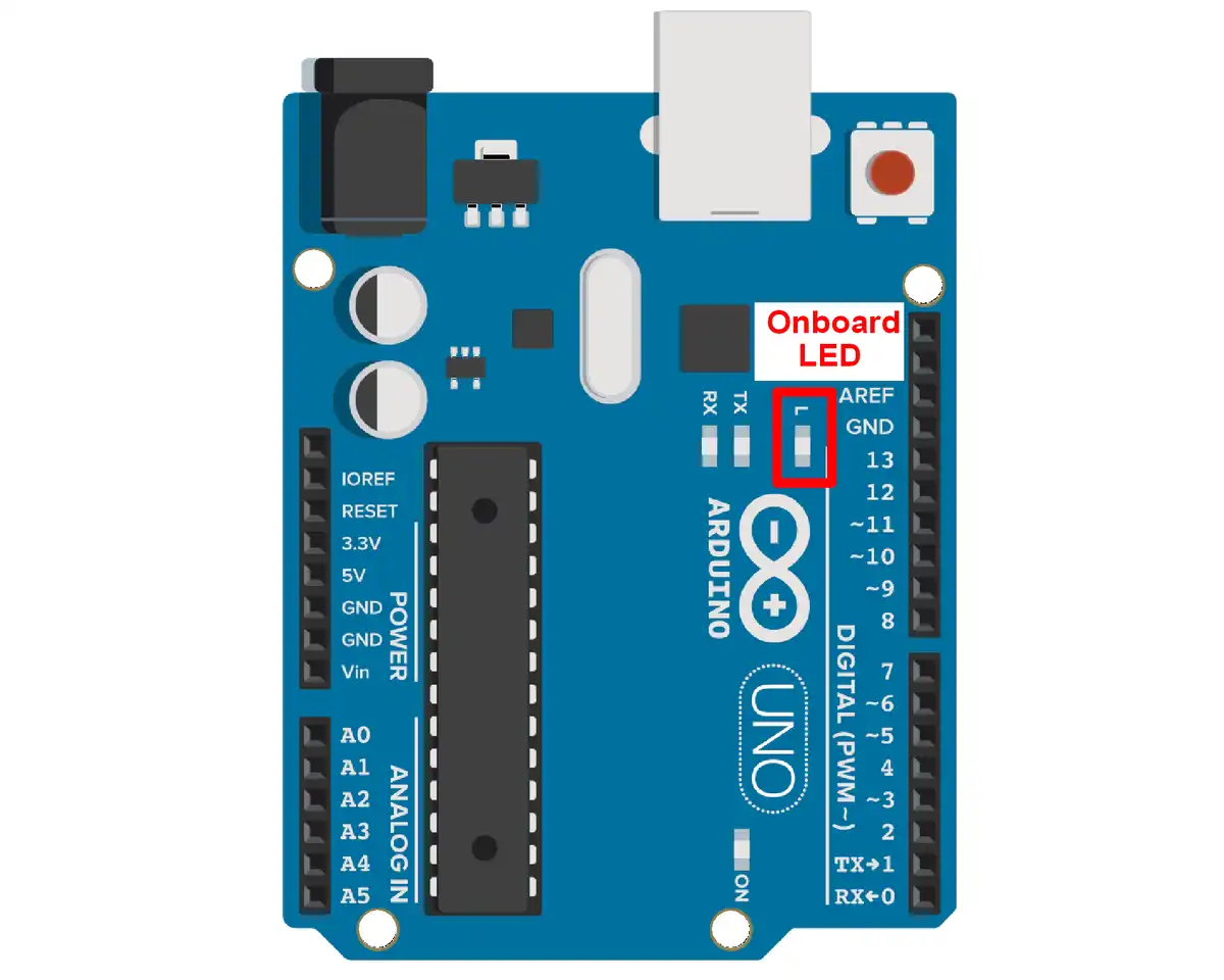
2. Arduino UNO example for LED blinking using timer interrupt
Code
// LED connected to pin 13 (built-in onboard LED)
const int ledPin = 13;
volatile bool ledState = false;

void setup() {
  pinMode(ledPin, OUTPUT);

  // Step 1: Disable interrupts during timer setup
  cli();

  // Step 2: Set Timer1 to CTC mode (Clear Timer on Compare Match)
  TCCR1A = 0;                // Normal port operation
  TCCR1B = 0;                // Clear previous settings
  TCCR1B |= (1 << WGM12);    // Set CTC mode

  // Step 3: Set compare value for desired time interval
  // Formula: OCR1A = (F_CPU / (2 * Prescaler * Frequency)) - 1
  // For 500ms: 1Hz = toggle every 1s → interrupt every 0.5s = 2Hz
  // Using Prescaler = 1024: OCR1A = 16,000,000 / (2 * 1024 * 2) - 1 ≈ 3905
  OCR1A = 3905;

  // Step 4: Set prescaler to 1024 and start the timer
  TCCR1B |= (1 << CS12) | (1 << CS10);  // Prescaler = 1024

  // Step 5: Enable Timer1 Compare Match A interrupt
  TIMSK1 |= (1 << OCIE1A);

  // Step 6: Enable global interrupts
  sei();
}

ISR(TIMER1_COMPA_vect) {
  ledState = !ledState;
  digitalWrite(ledPin, ledState);
}

void loop() {
  // Main loop does nothing – LED blinks via interrupt
}