70. AT Command System via UART
Connect a potentiometer and an LED to the microcontroller as shown in the image below.
Example using Arduino UNO:
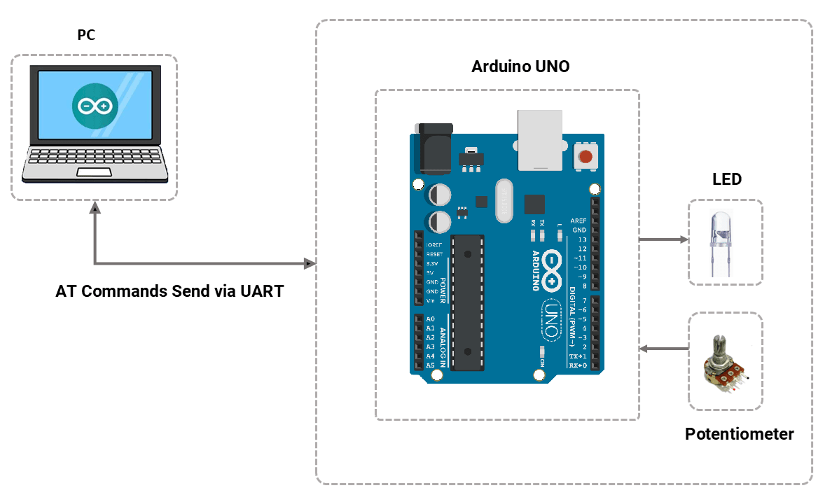
Build a system where the microcontroller communicates over UART and responds to specific AT commands received from a serial terminal (e.g., PuTTY, Arduino IDE Serial Monitor).
The microcontroller should:
- Continuously listen for AT commands via UART.
- Perform actions based on the received commands (e.g., read potentiometer value, turn LED ON/OFF).
- Send appropriate responses back to the serial terminal, as defined in the AT command table.
Refer to the AT command table below for the list of supported commands and their corresponding actions/responses.
AT-command table
| Sr. No | AT Commands | Action | Response to command |
| 1 | AT | - | OK |
| 2 | AT+LED=ON | Turn ON LED | +LED:”ON” |
| 3 | AT+LED=OFF | Turn OFF LED | +LED:”OFF” |
| 4 | AT+SYS_ON_TIME? | The Arduino was powered on. | +SYS_ON_TIME:”HH:MM:SS” |
| 5 | AT+LED_STATUS? | Check LED is ON or OFF and respond |
or
|
| 6 | AT+ADC_VALUE? | Read ADC value & respond |
range of <value> is 0 to (2^n) - 1 (adc value) |
| 7 | AT+ADC_VOLTAGE? | Read Voltage on ADC pin and respond |
range of <value> is 0 to VCC |
UART Basics
UART (Universal Asynchronous Receiver/Transmitter) is a full-duplex, asynchronous serial communication protocol that uses two wires, Tx and Rx.
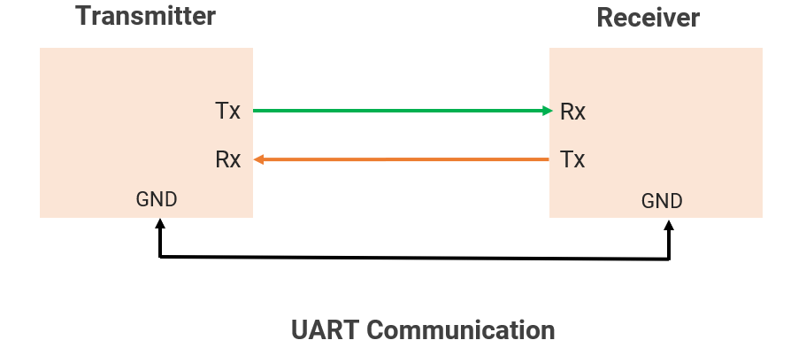
Note: RTS/CTS ( Request To Send / Clear To Send) hardware data flow control lines. Those are Optional.
Short-distance communication <10–50 cm, when using TTL voltage levels.
Limitations
1. Point-to-point communication only (not multi-master/slave like I2C/SPI)
2. Slower speed than SPI/I2C.
UART is commonly used for debugging with serial monitors, communicating with Bluetooth/Wi-Fi modules, GPS receivers, sensors, etc.
Baud Rate
- Baud rate is the number of bits transmitted per second.
For example, the baud rate is 4800, 9600, 19200, 57600, and 115200, etc.
- The clock signal is not present for synchronization, so the Tx/Rx sides must use the same baud rate for data transfer.
- Timing formula
1 bit transmission duration = 1 / Baud rate
E.g., 9600 baud, then 104.167 μs required to transmit 1 bit, and 9600 bits transmitted per second.
Communication Flow
UART is asynchronous(No clock is used), so both devices must use the same baud rate and data format for correct data transmission.
Frame Structure
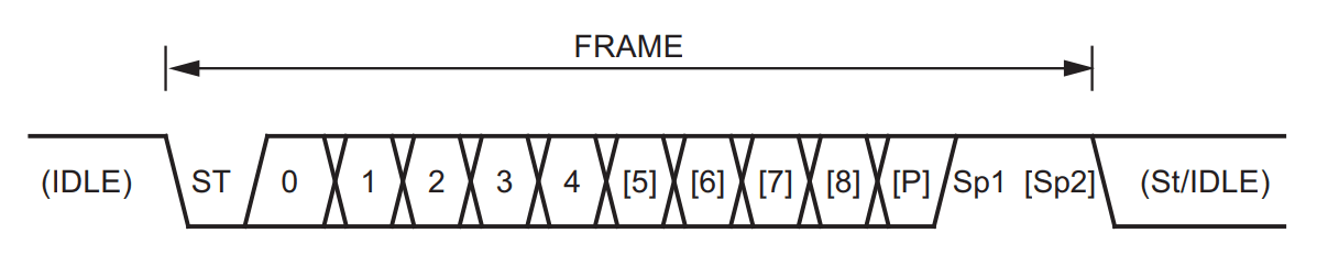
Frame Description
| Bit Name | Descriptions |
|---|---|
| Idle | TX and RX lines stay HIGH when idle |
| Start bit (ST) |
|
| Data bits | A number of data bits can be 5,6,7,8, or 9. |
| Parity(P) |
|
| Stop Bit (Sp) |
|
UART Signal Logic Levels: TTL UART and RS-232
The RS-232 is used for long-distance serial communication based on UART between two controllers.
| TTL UART | RS-232 | |
|---|---|---|
| Logic Levels | LOW: 0V HIGH : 3.3V / 5V | LOW : +3V TO +25V HIGH : -3V TO -25V |
| Logic Polarity | Non-Inverted | Inverted |
| Distance | Short-range (<10 - 50 cm) | Longer-range (up to 15m) |
| Interface | Directly with the Tx/Rx pins of a microcontroller. | Level shifter(e.g.MAX232 ) is used to connect RS-232 to controller (Directly connecting a controller to RS-232 can damage it due to incompatible voltage levels.) |
| Usage | Microcontrollers, Embedded Systems | Old PCs, Industrial Devices |
Error Detection
- Parity Bit: Checks if the number of 1’s in the data is even/odd.
- Even Parity: The Total number of 1s in the data is even.
- Odd Parity: The Total number of 1s is odd.
- No Parity: No error-checking bit is sent.
- Framing Error: If the stop bit is not received correctly
- Overrun Error: If a buffer is full and new data arrives
UART in Microcontroller
As an important communication protocol, it is present in all controllers, i.e., AVR, PIC, and ARM.
Understanding of UART considering the AVR (ATmega328P)controller.
Generally following registers are used for UART communication.
| Register | Description |
|---|---|
| UCSRA (8-bit) | USART Control and Status Register A: holds flags for UART transmission and reception status, data register empty, and error flags. |
| UCSRB (8-bit) | USART Control and Status Register B: Controls the enabling/disabling of transmission, reception, and interrupts. |
| UCSRC (8-bit) | USART Control and Status Register C: Configures UART baud rate, frame format, and communication mode |
| UBRR (16-bit) | USART Baud Rate Registers: Contains the baud rate setting for UART communication |
| UDR (8-bit) | USART Data Register: Holds the data to be transmitted or received via UART |
Fosc = System clock Frequency, e.g., 16MHz in Arduino UNO
UART Drivers
UART Data Transmission Driver
- Set Baud Rate: Configure the baud rate for communication.
- Configure Frame Format: Set data bits, parity, and stop bits.
- Enable Transmission: Enable the UART transmission to start sending data.
- Wait for the Data Register to Be Empty
- Write Data to UART data buffer: Write the data byte to the UART data buffer for transmission.
- Wait for Transmission to Complete.
- Optional: Disable Transmitter.
UART Data Reception Driver
- Enable Receiver: Enable the UART receiver to start receiving data.
- Wait for Data to Be Received: Wait until data is available in the UART data register.
- Read Data from UDR: Read the received data byte from the UART data register.
- Check for Errors: Ensure no framing, parity, or overrun errors occurred during reception.
- Process Received Data
- Optional: Disable Receiver
UART Pins in Arduino UNO Board
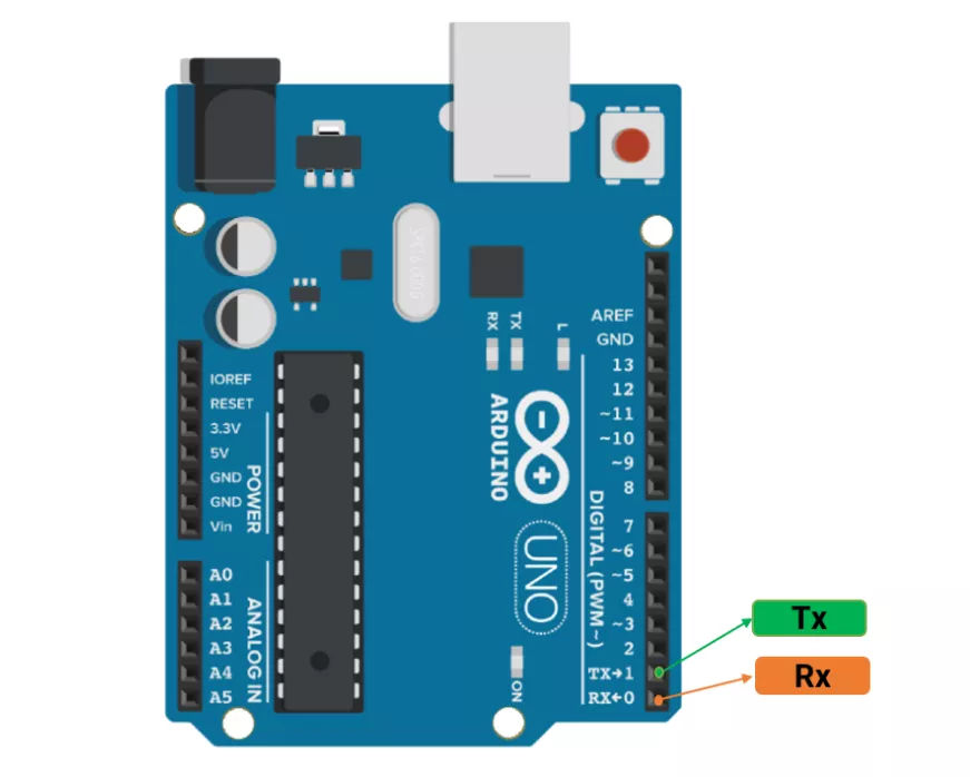
Arduino UNO Functions of UART Protocol
| Function | Description |
|---|---|
Serial.begin(baud) | Initialize UART |
Serial.print() | Send data |
Serial.println() | Send data with a newline and carriage return |
Serial.read() | Read 1 byte |
Serial.available() | Check if data is available |
Serial.write() | Send raw bytes |
Serial.end() | Disable UART |
Serial.availableForWrite() | Get a number of bytes available for writing in the Serial buffer. |
Serial.find() | Reads data from the serial buffer until the target is found. |
Serial.flush() | Waits for the transmission of outgoing serial data to complete. |
Serial.parseFloat() | Returns the first valid floating-point number. |
Serial.peek() | Returns the next byte in the RX buffer without removing it. |
Note:
1.The hardware serial library has a 64-byte buffer for data transmission/reception.
2.The serial library uses an interrupt to transmit data.
Example
Send character 'A' from one Arduino UNO to another via UART; on receiving 'A', the second UNO toggles an LED.
Hardware Connection Diagram
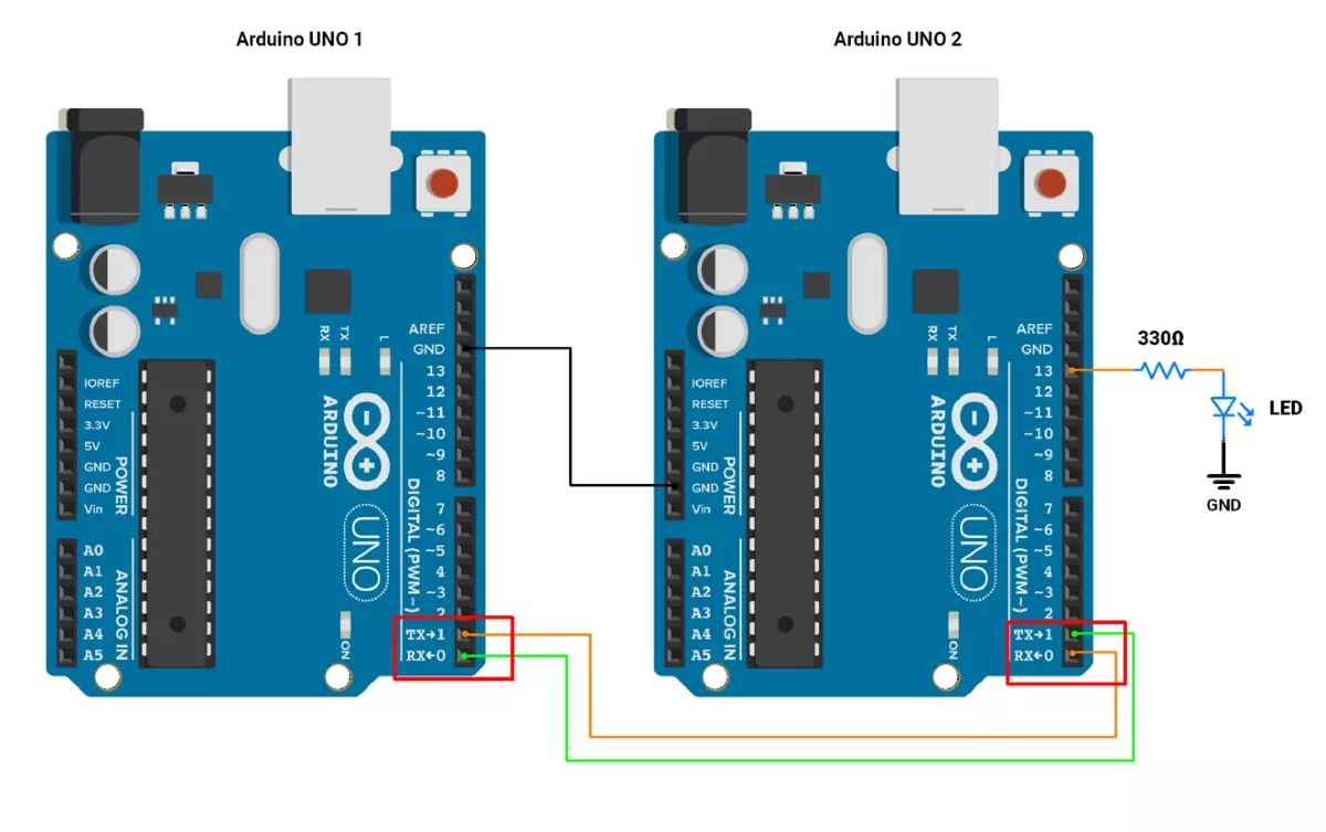
Arduino UNO 1 Code
void setup() {
  Serial.begin(9600); // Initialize UART at 9600 baud rate
}
void loop() {
  Serial.write('A');  // Send a character
  delay(1000);        // Send after every 1 second
}
Arduino UNO 2 Code
void setup() {
  Serial.begin(9600); // Initialize UART at 9600 baud rate
  pinMode(LED_BUILTIN, OUTPUT);
}

void loop() {
  if (Serial.available() > 0) {
    char receivedChar = Serial.read(); //Read the received Char
    if('A' == receivedChar)
    // Toggle LED when data is received
    digitalWrite(LED_BUILTIN, !digitalRead(LED_BUILTIN));

  }
}