70. AT Command System via UART
In this task, we are implementing an AT command system via UART using a microcontroller and a PC. The system allows users to send predefined AT commands from a PC to control an LED, read ADC values (from a potentiometer), and check system uptime.
- UART Communication
- UART (Universal Asynchronous Receiver/Transmitter) is a serial communication protocol used for exchanging data between microcontrollers and peripherals.
- It operates asynchronously, meaning no clock signal is needed.
- Key parameters: Baud rate (e.g., 115200), data bits (8), stop bits (1), parity (none).
- AT Commands
- AT (Attention) commands are text-based instructions used to interact with embedded systems.
- Example commands:
AT→ Basic acknowledgment (OK response).AT+LED=ON→ Turns LED on.AT+ADC_VALUE?→ Reads ADC value from a potentiometer.
- ADC (Analog-to-Digital Conversion)
- Converts analog voltage (e.g., from a potentiometer) to a digital value.
- Interrupt-Driven UART Reception
- Instead of polling, we can use interrupts to receive UART data efficiently.
Interfacing Components
| Component | Interface |
| UART | Serial Terminal (PC) |
| LED | GPIO pin |
| Potentiometer | ADC Channel |
So, by connecting and configuring the microcontroller and UART communication, we can implement the task.
Below are the solutions to the given task using different microcontrollers
- STM32
- ESP32
- Arduino UNO
We’re using an STM32 NUCLEO-F103RB board, which operates at a 3.3V logic level.
Key Peripherals Used:
- ADC1 – Reads the analog voltage from the potentiometer
- GPIO: For connecting the LED.
- USART2 –For UART communication between the microcontroller and the serial terminal.
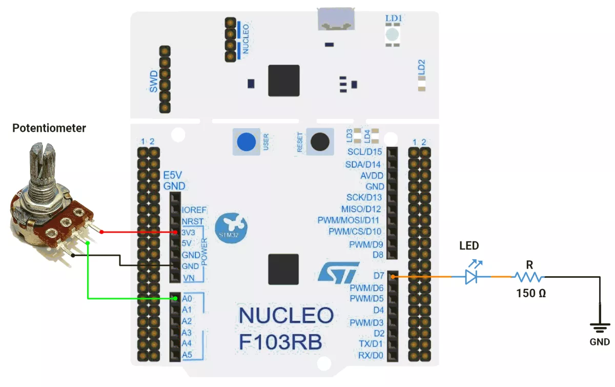
STM32 Hardware Connection
- Connect the middle pin of the potentiometer to PA0 (A0), and the outer pins to VCC and GND.
- Connect the LED to PA8 (D7) and configure it as an output with push-pull.
- Connect the STM32 NUCLEO-F103RB board to the PC via USB cable for UART communication and Power.
STM32 Firmware Implementation
Project Setup in STM32CubeIDE
- Create a Project
- Open STM32CubeIDE, start a new project, and select the NUCLEO-F103RB board.
- Basic Configuration (via CubeMX inside CubeIDE)
- Clock: Use the default HSI oscillator with PLL enabled (as configured in SystemClock_Config).
- GPIO: Enable clocks for PORTA, PORTB, PORTC, and PORTD.
- LED: Set PA8(D7) as GPIO Output Push-Pull
- ADC1 (Analog Input Source)
- Resolution: 12-bit (0–4095 range).
- Conversion mode: Single, software-triggered.
- Channel: ADC_CHANNEL_0 (PA0).
- UART2
- Set Mode to Asynchronous
- Configure parameters:
- Baud Rate: 115200
- Word Length: 8 bits
- Parity: None
- Stop Bits: 1
- Hardware Flow Control: None
- Interrupt: Enable UART2 Global Interrupt in NVIC.
- The NUCLEO-F103RB board has USART2 connected to the ST-LINK virtual COM port (PA2 and PA3)
- Code Generation
- CubeMX will automatically generate all the startup code, including:
HAL_Init()→ Initializes HAL and system tick.SystemClock_Config()→ Configures system clock (HSI + PLL).MX_GPIO_Init()→ Initializes GPIO ports.MX_USART2_UART_Init()→ Configures UART2.MX_ADC1_Init()→ Configures ADC1.
- This code sets up the hardware and prepares the project for firmware development, so we only need to add our application logic in the user code sections
- CubeMX will automatically generate all the startup code, including:
Code Snippets from main.c
ADC Initialization (MX_ADC1_Init)
  hadc1.Instance = ADC1;
  hadc1.Init.ScanConvMode = ADC_SCAN_DISABLE;
  hadc1.Init.ContinuousConvMode = DISABLE;
  hadc1.Init.DiscontinuousConvMode = DISABLE;
  hadc1.Init.ExternalTrigConv = ADC_SOFTWARE_START;
  hadc1.Init.DataAlign = ADC_DATAALIGN_RIGHT;
  hadc1.Init.NbrOfConversion = 1;
  if (HAL_ADC_Init(&hadc1) != HAL_OK) {
    Error_Handler();
  }

  sConfig.Channel = ADC_CHANNEL_0;
  sConfig.Rank = ADC_REGULAR_RANK_1;
  sConfig.SamplingTime = ADC_SAMPLETIME_239CYCLES_5;
  if (HAL_ADC_ConfigChannel(&hadc1, &sConfig) != HAL_OK) {
    Error_Handler();
}- Initializes ADC1 in single-channel mode, software-triggered conversion, with Channel 0 configured for a 239.5-cycle sampling time.
GPIO Initialization (MX_GPIO_Init)
/*Configure GPIO pin : PA8 */
 GPIO_InitStruct.Pin = GPIO_PIN_8;
 GPIO_InitStruct.Mode = GPIO_MODE_OUTPUT_PP;
 GPIO_InitStruct.Pull = GPIO_NOPULL;
 GPIO_InitStruct.Speed = GPIO_SPEED_FREQ_LOW;
HAL_GPIO_Init(GPIOA, &GPIO_InitStruct);- PA8 as output push-pull (for LED control).
- No pull resistor, low-speed (
GPIO_SPEED_FREQ_LOW).
UART Initialization (MX_USART2_UART_Init)
 huart2.Instance = USART2;
 huart2.Init.BaudRate = 115200;
 huart2.Init.WordLength = UART_WORDLENGTH_8B;
 huart2.Init.StopBits = UART_STOPBITS_1;
 huart2.Init.Parity = UART_PARITY_NONE;
 huart2.Init.Mode = UART_MODE_TX_RX;
 huart2.Init.HwFlowCtl = UART_HWCONTROL_NONE;
 huart2.Init.OverSampling = UART_OVERSAMPLING_16;
 if (HAL_UART_Init(&huart2) != HAL_OK)
 {
   Error_Handler();
}- Baud rate: 115200, 8-bit data, no parity, 1 stop bit.
- Transmit/receive mode (
UART_MODE_TX_RX).
Header Includes, Defines, and Variables
#include <stdio.h>      // Provides sprintf, printf (string formatting and printing)
#include <string.h>     // Provides string operations (strcmp, strcpy, strlen etc.)
Circular Buffer Structure
#define RX_BUFFER_SIZE 128   // Maximum size of UART circular buffer

typedef struct {
    uint8_t buffer[RX_BUFFER_SIZE]; // Storage array for incoming UART data
    volatile uint16_t head;         // Write index (producer)
    volatile uint16_t tail;         // Read index (consumer)
} CircularBuffer;- A circular buffer (ring buffer) efficiently stores UART incoming data in FIFO order.
- The head points to where the next byte will be written, tail points to where the next byte will be read.
- volatile ensures the compiler doesn’t optimize out updates from ISRs.
ADC & Hardware Constants
#define ADC_MAX_VALUE       4095   // 12-bit ADC maximum value
#define ADC_REF_VOLTAGE     3.3    // Reference voltage (Vref+)
#define VOLTAGE_OFFSET      0.05   // Calibration offset for accuracy

#define LED0_PORT GPIOA           // LED connected to GPIOA
#define LED0_PIN GPIO_PIN_8 // LED pin is PA8- These constants simplify ADC-to-voltage conversion and GPIO operations.
Global Buffers and Flags
char uartTXBuffer[50];       // UART transmit buffer for formatted messages
uint8_t uartRXByte;          // Single received UART byte
CircularBuffer uartRxCB;     // Circular buffer for UART reception

char receivedData[30];       // Stores complete received command string
uint8_t strReceivedFlag = 0; // Flag = 1 when a valid command string is ready- uartRXByte: temporary storage for ISR received byte.
- receivedData: command string extracted from UART.
- strReceivedFlag: ensures the main loop processes commands only when fully received.
Private Functions
Circular Buffer Utility Functions
/* ====== Circular Buffer Utility Functions ====== */
static inline void CB_Init(CircularBuffer *cb) {
    cb->head = 0;   // Reset head
    cb->tail = 0;   // Reset tail
}

static inline uint8_t CB_IsEmpty(CircularBuffer *cb) {
    return (cb->head == cb->tail); // True if no data
}

static inline uint8_t CB_IsFull(CircularBuffer *cb) {
    return ((cb->head + 1) % RX_BUFFER_SIZE == cb->tail); // Next position wraps to tail
}

static inline void CB_Push(CircularBuffer *cb, uint8_t data) {
    if (!CB_IsFull(cb)) {
        cb->buffer[cb->head] = data;                  // Store byte
        cb->head = (cb->head + 1) % RX_BUFFER_SIZE;   // Move head
    }
}

static inline uint8_t CB_Pop(CircularBuffer *cb, uint8_t *data) {
    if (!CB_IsEmpty(cb)) {
        *data = cb->buffer[cb->tail];                 // Read byte
        cb->tail = (cb->tail + 1) % RX_BUFFER_SIZE;   // Move tail
        return 1;  // Success
    }
    return 0;      // No data available
}- Provides FIFO behavior for UART Rx handling.
- Prevents data loss and avoids blocking.
UART Support Functions
static void printOnSerialMonitor(const char *msg) {
    HAL_UART_Transmit(&huart2, (uint8_t*) msg, strlen(msg), HAL_MAX_DELAY);
}- Sends a string reliably to the UART terminal.
static void floatToStr(float val, char *buffer, uint8_t decimals) {
	int32_t whole = (int32_t) val;
	float fraction = val - whole;
	if (val < 0)
		fraction *= -1;

	int32_t n = whole;
	uint8_t i = 0;
	char temp[10];

	if (n == 0)
		buffer[i++] = '0';
	else {
		if (n < 0) {
			buffer[i++] = '-';
			n = -n;
		}
		uint8_t j = 0;
		while (n > 0) {
			temp[j++] = (n % 10) + '0';
			n /= 10;
		}
		while (j > 0)
			buffer[i++] = temp[--j];
	}
	buffer[i++] = '.';
	for (uint8_t d = 0; d < decimals; d++) {
		fraction *= 10;
		uint8_t digit = (uint8_t) fraction;
		buffer[i++] = digit + '0';
		fraction -= digit;
	}
	buffer[i] = '\0';
}- Handles integer + fractional conversion manually.
- Useful in embedded systems without heavy sprintf floating-point support.
Hardware Functions
ADC Operations
void readAndPrintPOTADCValue() {
    HAL_ADC_Start(&hadc1);
    HAL_ADC_PollForConversion(&hadc1, 20);
    sprintf(uartTXBuffer, "+ADC_VALUE: %lu \r\n", HAL_ADC_GetValue(&hadc1));
    printOnSerialMonitor(uartTXBuffer);
}- Reads raw ADC digital value and prints via UART.
void readAndPrintPOTADCVoltage() {
    char potADCVoltageValueStr[10];
    HAL_ADC_Start(&hadc1);
    HAL_ADC_PollForConversion(&hadc1, 20);
    float potADCVoltageValue = ((HAL_ADC_GetValue(&hadc1) * ADC_REF_VOLTAGE) / ADC_MAX_VALUE) + VOLTAGE_OFFSET;
    floatToStr(potADCVoltageValue, potADCVoltageValueStr, 3);
    sprintf(uartTXBuffer, "+ADC_VOLTAGE: %s \r\n", potADCVoltageValueStr);
    printOnSerialMonitor(uartTXBuffer);
}- Converts ADC value → real voltage (with offset correction).
- Prints as a formatted string.
System Monitoring
void printSysOnTime() {
    uint32_t uptime = HAL_GetTick();  // System tick (ms since reset)
    uint16_t hours = uptime / 3600000;
    uint8_t minutes = (uptime % 3600000) / 60000;
    uint8_t seconds = (uptime % 60000) / 1000;
    sprintf(uartTXBuffer, "+SYS_ON_TIME: %d:%d:%d \r\n", (int) hours, (int) minutes, (int) seconds);
    printOnSerialMonitor(uartTXBuffer);
}- Reports system uptime in HH:MM:SS.
LED Control
void printLEDStatus() {
    if (HAL_GPIO_ReadPin(LED0_PORT, LED0_PIN))
        sprintf(uartTXBuffer, "+LED_STATUS:\"ON\" \r\n");
    else
        sprintf(uartTXBuffer, "+LED_STATUS:\"OFF\" \r\n");
    printOnSerialMonitor(uartTXBuffer);
}

void printTurnONLED() {
    HAL_GPIO_WritePin(LED0_PORT, LED0_PIN, 1);
    sprintf(uartTXBuffer, "+LED:\"ON\" \r\n");
    printOnSerialMonitor(uartTXBuffer);
}

void printTurnOFFLED() {
    HAL_GPIO_WritePin(LED0_PORT, LED0_PIN, 0);
    sprintf(uartTXBuffer, "+LED:\"OFF\" \r\n");
    printOnSerialMonitor(uartTXBuffer);
}
- Provides AT command-driven LED control (ON/OFF/status).
UART Rx Handling
void HAL_UART_RxCpltCallback(UART_HandleTypeDef *huart) {
    if (huart->Instance == USART2) {
        CB_Push(&uartRxCB, uartRXByte);  // Push received byte into circular buffer
        uartStartReception();            // Restart UART reception interrupt
    }
}

void uartStartReception() {
    HAL_UART_Receive_IT(&huart2, &uartRXByte, 1); // Enable interrupt-driven UART reception
}- Callback stores each received byte in a circular buffer.
- Ensures non-blocking UART reception.
void trimString(char *str) {
    int i = strlen(str) - 1;
    while (i >= 0 && (str[i] == '\r' || str[i] == '\n' || str[i] == ' ')) {
        str[i] = '\0';   // Remove trailing whitespace/newlines
        i--;
    }
}- Cleans received the command string for safe comparison.
Main Loop Logic
CB_Init(&uartRxCB);       // Initialize circular buffer
uartStartReception();     // Start UART reception interrupt

uint8_t rxByte;
static char cmdBuffer[30];
static uint8_t cmdIndex = 0;

while (1) {
  // Process circular buffer
  while (CB_Pop(&uartRxCB, &rxByte)) {
    if (rxByte == '\r' || rxByte == '\n') {
      if (cmdIndex > 0) {
        cmdBuffer[cmdIndex] = '\0';
        strcpy(receivedData, cmdBuffer);
        strReceivedFlag = 1;
        cmdIndex = 0;
      }
    } else if (cmdIndex < sizeof(cmdBuffer) - 1) {
      cmdBuffer[cmdIndex++] = rxByte;
      HAL_UART_Transmit(&huart2, &rxByte, 1, HAL_MAX_DELAY); // Echo received byte back
    }
  }

  if (strReceivedFlag) {
    strReceivedFlag = 0;
    trimString(receivedData);

    sprintf(uartTXBuffer, " Received: %s \r\n", receivedData);
    printOnSerialMonitor(uartTXBuffer);

    if (strcmp(receivedData, "AT") == 0) {
      sprintf(uartTXBuffer, "OK\r\n");
      printOnSerialMonitor(uartTXBuffer);
    } else if (strcmp(receivedData, "AT+LED=ON") == 0) {
      printTurnONLED();
    } else if (strcmp(receivedData, "AT+LED=OFF") == 0) {
      printTurnOFFLED();
    } else if (strcmp(receivedData, "AT+LED_STATUS?") == 0) {
      printLEDStatus();
    } else if (strcmp(receivedData, "AT+ADC_VALUE?") == 0) {
      readAndPrintPOTADCValue();
    } else if (strcmp(receivedData, "AT+ADC_VOLTAGE?") == 0) {
      readAndPrintPOTADCVoltage();
    } else if (strcmp(receivedData, "AT+SYS_ON_TIME?") == 0) {
      printSysOnTime();
    } else {
      sprintf(uartTXBuffer, "Invalid Command! \r\n");
      printOnSerialMonitor(uartTXBuffer);
    }
  }
}
Flow of Main Loop
Setup Phase
- Circular buffer is initialized.
- UART reception with interrupts is enabled.
- Command buffer and flags are prepared.
UART Data Handling
- Incoming bytes are read from the circular buffer.
- If a newline (
\r/\n) is detected, → command is considered complete. - Completed command is copied to receivedData, and a flag is raised.
- Otherwise, the byte is appended to cmdBuffer and echoed back to the UART.
Command Execution
- When a full command is received:
- The buffer is reset, and the command is displayed.
- Command is compared with supported AT-style instructions:
AT→ Acknowledgement (OK).AT+LED=ON/OFF→ LED control.AT+LED_STATUS?→ LED state feedback.AT+ADC_VALUE?→ Raw ADC reading.AT+ADC_VOLTAGE?→ Converted ADC voltage.AT+SYS_ON_TIME?→ System uptime in ms.- Any other input → “Invalid Command!”.
Example Workflow
- User sends AT+LED=ON → LED turns on, UART confirms +LED:"ON".
- User queries voltage → +ADC_VOLTAGE: 2.105 reflects potentiometer position.
- Uptime query shows +SYS_ON_TIME: 1:30:45 after 1.5 hours.
Download Project
The complete STM32CubeIDE project (including .ioc configuration, main.c, and HAL files) is available here:
📥 Download Project
We are using the ESP32 DevKit v4 development board and programming it using the Arduino IDE.
- Before uploading, make sure to select “ESP32 Dev Module” as the board to ensure correct settings and compatibility.
On the ESP32 DevKit V4, a USB-to-UART bridge chip (either CP2102 or CH340C) is integrated on the board.
This chip converts USB data from the PC into UART signals, which are sent to UART0 of the ESP32 (TX0 – GPIO1, RX0 – GPIO3).
UART0 is used for programming the ESP32 and for communication with the Serial Monitor.
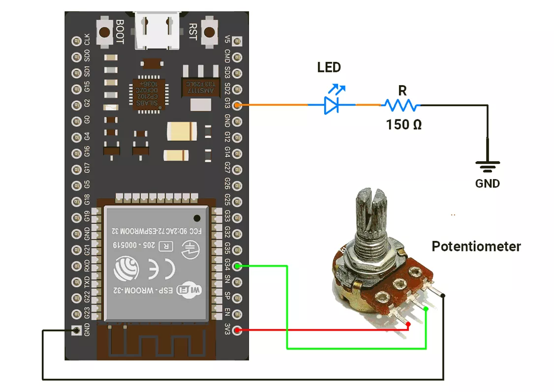
ESP32 Circuit Connection
- Connect the LED to GPIO pin 13 with a 150Ω resistor.
- Connect the potentiometer to the GPIO pin 34.
ESP32 Code
#define ADC_Value 34  // ADC pin for analog input
#define LED_pin 13     // GPIO pin for LED

String receivedData;  // Stores incoming serial data
float volt;           // Stores calculated voltage


void setup() {
  Serial.begin(115200);      // Start UART at 115200 baud
  pinMode(LED_pin, OUTPUT);  // Configure LED pin as output
}

void loop() {
  if (Serial.available() > 0) {  // Check if serial data is available
    receivedData = Serial.readString();
    receivedData.trim();  // Remove whitespace/newline

    Serial.print("Received: ");
    Serial.println(receivedData);  // Echo received command

    if (receivedData == "AT") {
      Serial.println("OK");  // Basic AT response
    } else if (receivedData == "AT+LED=ON") {
      digitalWrite(LED_pin, HIGH);  // Turn LED ON
      Serial.println("+LED:\"ON\"");
    } else if (receivedData == "AT+LED=OFF") {
      digitalWrite(LED_pin, LOW);  // Turn LED OFF
      Serial.println("+LED:\"OFF\"");
    } else if (receivedData == "AT+LED_STATUS?") {
      // Report LED state
      if (digitalRead(LED_pin) == HIGH) {
        Serial.println("+LED_STATUS:\"ON\"");
      } else {
        Serial.println("+LED_STATUS:\"OFF\"");
      }
    } else if (receivedData == "AT+ADC_VALUE?") {
      int adcVal = analogRead(ADC_Value);  // Read raw ADC value
      Serial.print("+ADC_VALUE:");
      Serial.println(adcVal);
    } else if (receivedData == "AT+ADC_VOLTAGE?") {
      int adcVal = analogRead(ADC_Value);  // Read ADC value
      volt = (3.3 * adcVal) / 4095.0;      // Convert to voltage (12-bit, 3.3V ref)
      Serial.print("+ADC_VOLTAGE:");
      Serial.println(volt, 2);  // Print with 2 decimals
    } else if (receivedData == "AT+SYS_ON_TIME?") {
      unsigned long uptime = millis();  // System uptime (ms)

      // Convert ms → HH:MM:SS
      unsigned long hours = uptime / 3600000;
      unsigned long minutes = (uptime % 3600000) / 60000;
      unsigned long seconds = (uptime % 60000) / 1000;

      char timeBuffer[9];  // Store formatted time
      sprintf(timeBuffer, "%02lu:%02lu:%02lu", hours, minutes, seconds);

      Serial.print("+SYS_ON_TIME:");
      Serial.println(timeBuffer);
    } else {
      Serial.println("Invalid Command!");  // Handle wrong command
    }
  }
}
Code Explanation
- The code works like an AT-command interpreter on ESP32.
- It waits for serial input, trims (cleans) the received string, and compares it with known commands.
- If the command is AT → it replies OK.
- If the command is AT+LED=ON → it turns the LED ON and replies +LED:"ON".
- If the command is AT+LED=OFF → it turns the LED OFF and replies +LED:"OFF".
- If the command is AT+LED_STATUS? → it checks the LED state and replies +LED_STATUS:"ON" or +LED_STATUS:"OFF".
- If the command is AT+ADC_VALUE? → it reads the raw ADC value (0–4095) and replies +ADC_VALUE:<value>.
- If the command is AT+ADC_VOLTAGE? → it converts the ADC reading into voltage (0–3.3 V) and replies +ADC_VOLTAGE:<voltage> with two decimal places.
- If the command is AT+SYS_ON_TIME? → it calculates uptime in HH:MM:SS format and replies +SYS_ON_TIME:HH:MM:SS.
- If the input does not match any known command → it replies Invalid Command!.
We are using the Arduino UNO development board and programming it using the Arduino IDE.
- Before uploading, make sure to select “Arduino UNO” as the board to ensure correct settings and compatibility.
The Arduino UNO will be connected to a PC via USB, enabling Serial communication between the Arduino UNO and the Serial Monitor for sending and receiving commands.
In the given task, we will send AT commands from the Serial Monitor, and the Arduino UNO will respond to these commands accordingly.
Setting the Baud Rate
- We will ensure that both the Arduino UNO and the Serial Monitor are set to the same baud rate (e.g., 9600, 115200) for proper communication.
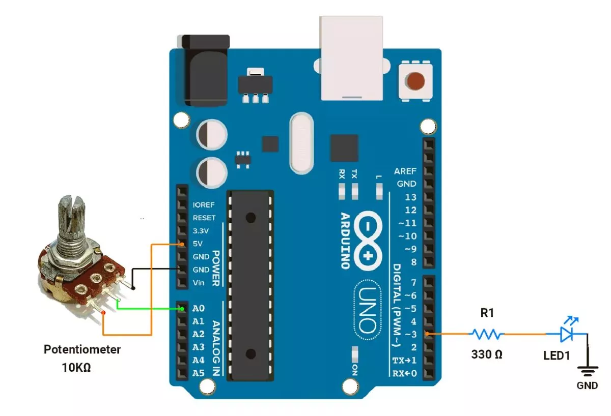
Arduino UNO Hardware Connection
Let’s connect the hardware,
- LED connected to digital pin 3 using a 330Ω resistor in series with the LED to limit current through it.
- Potentiometer: Connect the middle pin of the potentiometer to A0, and the outer pins to VCC and GND.
Circuit Diagram
Arduino UNO Code
#define ADC_Value A0
#define LED_pin 3

String receivedData;
float volt;


void setup() {
  Serial.begin(115200);      // Initialize UART communication at 115200 baud rate
  pinMode(LED_pin, OUTPUT);  // Set LED pin as output
}

void loop() {
  if (Serial.available() > 0) {  // Check if data is received
    receivedData = Serial.readString();
    receivedData.trim();  // Remove trailing newline or spaces

    Serial.print("Received: ");
    Serial.println(receivedData);  // Print received data

    if (receivedData == "AT") {
      Serial.println("OK");
    } else if (receivedData == "AT+LED=ON") {
      digitalWrite(LED_pin, HIGH);
      Serial.println("+LED:\"ON\"");
    } else if (receivedData == "AT+LED=OFF") {
      digitalWrite(LED_pin, LOW);
      Serial.println("+LED:\"OFF\"");
    } else if (receivedData == "AT+LED_STATUS?") {

      // Check LED status and report
      if (digitalRead(LED_pin) == HIGH) {
        Serial.println("+LED_STATUS:\"ON\"");
      } else {
        Serial.println("+LED_STATUS:\"OFF\"");
      }
    } else if (receivedData == "AT+ADC_VALUE?") {
      int adcVal = analogRead(ADC_Value);  // Read ADC
      Serial.print("+ADC_VALUE:");
      Serial.println(adcVal);
    } else if (receivedData == "AT+ADC_VOLTAGE?") {
      int adcVal = analogRead(ADC_Value);
      volt = (5.0 * adcVal) / 1023.0;
      Serial.print("+ADC_VOLTAGE:");
      Serial.println(volt, 2);  // Prints voltage with 2 decimal places
    } else if (receivedData == "AT+SYS_ON_TIME?") {
      // Get system uptime in milliseconds
      unsigned long uptime = millis();

      // Convert uptime to hours, minutes, seconds
      unsigned long hours = uptime / 3600000;              // 1 hour = 3600000 milliseconds
      unsigned long minutes = (uptime % 3600000) / 60000;  // 1 minute = 60000 milliseconds
      unsigned long seconds = (uptime % 60000) / 1000;     // 1 second = 1000 milliseconds

      // Print uptime in HH:MM:SS format
      char timeBuffer[9];  // Buffer for "HH:MM:SS"
      sprintf(timeBuffer, "%02lu:%02lu:%02lu", hours, minutes, seconds);

      Serial.print("+SYS_ON_TIME:");
      Serial.println(timeBuffer);
    } else {
      Serial.println("Invalid Command!");  // Handles unknown inputs
    }
  }
}
Code Explanation
- Setup
- Initializes Serial communication at 115200 baud rate.
- Sets pin 3 as output for LED control.
- Main Loop
- Listens for commands from the Serial Monitor. Serial.available(); check whether data is available in the buffer.
- Serial.readString(); Read the string available in the receive buffer.
- Processes commands to control the LED, read ADC values, and system uptime.
- Supported Commands
AT→ Responds with OK.AT+LED=ON→ Turns LED ON, responds+LED:"ON".AT+LED=OFF→ Turns LED OFF, responds+LED:"OFF".AT+LED_STATUS?→ Reports LED status:+LED_STATUS:"ON" or "OFF".AT+ADC_VALUE?→ Reads analog pin (A0), responds with+ADC_VALUE:<0-1023>.AT+ADC_VOLTAGE?→ Converts ADC reading to voltage (0-5V), responds+ADC_VOLTAGE:<value>.AT+SYS_ON_TIME?→ Reports system uptime inHH:MM:SS.
- Error Handling
- Unknown commands respond with "
Invalid Command!".
- Unknown commands respond with "
Output
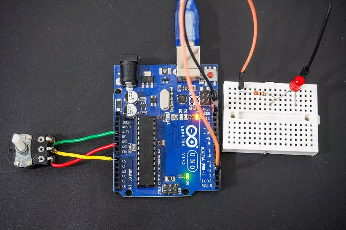
Hardware Setup
Video