18. Bar Graph
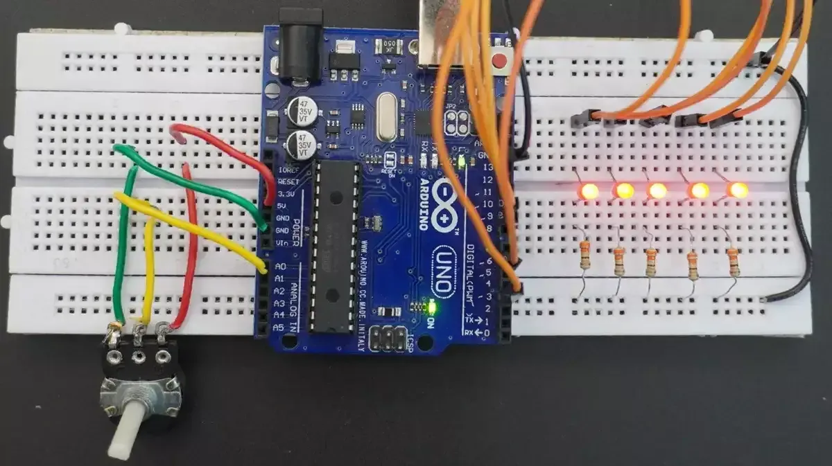
We’re going to build a simple LED bar graph using a potentiometer.
As we rotate the potentiometer, the LEDs will light up one by one smoothly.
Solving Approach:
- We’ll split the potentiometer’s ADC range into 5 equal parts (since we have 5 LEDs).
- In each part, the current LED gradually increases its brightness from 0% to 100%.
- We’ll use PWM to smoothly control LED brightness and map the potentiometer’s ADC value to PWM duty cycle for each LED.
- All earlier LEDs stay fully ON, and the later ones stay OFF.
- This gives a nice bar graph effect, like the LEDs are “filling up” smoothly as you rotate the knob.
So we have to interface a potentiometer and five LEDs with a microcontroller.
Potentiometer & LED Interfacing
Potentiometer Interfacing
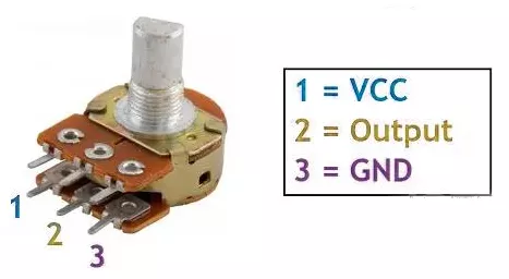
- Connection: Connect the potentiometer terminals 1 and 3 to VCC and GND or vice versa. Terminal 2 (wiper) to the MCU ADC pin.
Note: We can use any of the potentiometers with values between 1kΩ and 10kΩ.
Five LEDs Interfacing
Connect each PWM GPIO pin to an anode of a separate LED, and the cathode of each LED to GND with a current-limiting resistor in series to protect LEDs and GPIO pins.
Calculating the current-limited Resistor Value
Case 1: 5V Supply
- LED forward voltage (Vf) = 1.8V (from datasheet)
- Voltage across resistor (VR) = Supply voltage – Vf = 5V – 1.8V = 3.2V
- Resistor value (R) = VR / I = 3.2V / 10 mA = 320 Ω
Standard resistor values near 320 Ω: 330 Ω or 300 Ω (whichever is available).
Similarly, Case 2: 3.3V Supply
- Voltage across resistor (VR) = 3.3V – 1.8V = 1.5V
- Resistor value (R) = 1.5V / 10 mA = 150 Ω
Standard resistor value: 150 Ω.
So, by selecting a proper resistor, LED, and potentiometer connections, we can implement the task.
Below are the solutions to the given task using different microcontrollers
- STM32
- ESP32
- Arduino UNO
We’re using an STM32 NUCLEO-F103RB board, which runs at a 3.3V logic level.
Key Peripherals Used
- ADC1 Channel 0 (PA0): Reads the analog voltage from the potentiometer.
- TIM1 for PWM on channels 1, 2, and 3 (PA8, PA9, PA10).
- TIM3 for PWM on channels 1 and 2 (PA6, PA7).
- GPIO: PA8, PA9, PA10, PA6, and PA7 are configured as alternate function pins for PWM output.
- Optional USART2: Used for serial debugging (configured but not used here).
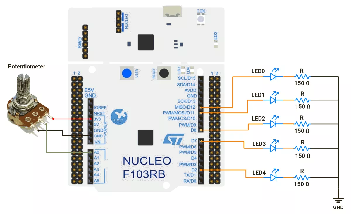
STM32 Hardware Connection
- Potentiometer Setup:
- Connect the potentiometer’s middle pin to PA0 (ADC1_IN0) for analog input.
- Connect the other two pins to 3.3V (VCC) and GND to create a voltage divider.
- Use a 10kΩ potentiometer for best results.
- LED Setup:
- PWM Output Pin: PA8 (TIM1 Channel 1).
- Connect the LED anode (long leg) to PA8.
- Connect the LED cathode (short leg) to GND through a 150Ω resistor.
- Repeat similar connections for PA9, PA10, PA6, and PA7.
Circuit Diagram
STM32 Firmware Implementation
Project Setup in STM32CubeIDE:
- Create a Project
- Open STM32CubeIDE, start a new project, and select the NUCLEO-F103RB board.
- Basic Configuration (via CubeMX inside CubeIDE)
- Clock: Use the default HSI oscillator with PLL enabled (configured in
SystemClock_Config). - GPIO:
- GPIO clocks enabled for PORTA, PORTB, PORTC, PORTD.
- GPIO pins for ADC input (PA0) and PWM output pins are auto-configured via CubeMX.
- ADC1 (Analog Input Source):
- Resolution: 12-bit (0–4095 range).
- Conversion mode: Single, software triggered.
- Channel: ADC_CHANNEL_0 (PA0).
- Timer 1 (TIM1 – PWM Generator):
- Prescaler = 0 → Timer clock = APB2.
- Period (ARR) = 4095 → Matches ADC 12-bit resolution for direct mapping.
- PWM Mode 1 enabled on Channels 1, 2, and 3.
- Timer 3 (TIM3 – PWM Generator):
- Prescaler = 0.
- Period (ARR) = 4095.
- PWM Mode 1 enabled on Channels 1 and 2.
- USART2: Enabled at 115200 baud, 8-N-1, for debugging/expansion if needed.
- Clock: Use the default HSI oscillator with PLL enabled (configured in
- Code Generation
- CubeMX will automatically generate all the startup code, including:
HAL_Init()→ Initializes the HAL library.SystemClock_Config()→ Configures HSI + PLL system clock.MX_GPIO_Init()→ Initializes all GPIO ports.MX_ADC1_Init()→ Configures ADC1 for analog input.MX_TIM1_Init()→ Configures TIM1 for PWM output.MX_TIM3_Init()→ Configures TIM3 for PWM output.MX_USART2_UART_Init()→ Initializes UART2 for debugging.
- This code sets up the hardware and prepares the project for firmware development, so we only need to add our application logic in the user code sections
- CubeMX will automatically generate all the startup code, including:
Code Snippets from main.c
ADC Initialization (MX_ADC1_Init):
hadc1.Instance = ADC1;
hadc1.Init.ScanConvMode = ADC_SCAN_DISABLE;
hadc1.Init.ContinuousConvMode = DISABLE;
hadc1.Init.DataAlign = ADC_DATAALIGN_RIGHT;
This configures ADC1 for single-channel operation with right-aligned 12-bit results.
Timer Initialization (MX_TIM1_Init and MX_TIM3_Init):
htim1.Init.Period = 4095;  // ARR register value
htim1.Init.Prescaler = 0;  // No prescaling
sConfigOC.OCMode = TIM_OCMODE_PWM1;  // PWM Mode 1

//Similar configuration is applied for TIM3 as well.
These functions configure timers for PWM generation.
Variable Definitions and Macros:
The provided code defines timer handles and channel mappings for cleaner code organization:
#define LED0_TIM_HANDLE        &htim3
#define LED0_TIM_CHANNEL       TIM_CHANNEL_1
// Additional LED mappings...

uint16_t g_adcSection1 = (ADC_MAX_VALUE / 5) * 1;  // 819
uint16_t g_adcSection2 = (ADC_MAX_VALUE / 5) * 2;  // 1638
// Additional section boundaries…

// ADC value range (12-bit ADC)
#define ADC_MIN_VALUE          0
#define ADC_MAX_VALUE          4095

// PWM duty cycle range
#define PWM_MIN_VALUE          0
#define PWM_MAX_VALUE          4095
Custom Mapping Function:
The mapValue() function provides linear interpolation between ranges:
uint16_t mapValue(uint16_t x, uint16_t inMin, uint16_t inMax,
                  uint16_t outMin, uint16_t outMax) {
    return (x - inMin) * (outMax - outMin) / (inMax - inMin) + outMin;
}
This function scales ADC values (0-4095) to PWM duty cycle values (0-4095) within each segment.
PWM Initialization in main():
Before the while loop, PWM channels are enabled:
HAL_TIM_PWM_Start(LED0_TIM_HANDLE, LED0_TIM_CHANNEL);
HAL_TIM_PWM_Start(LED1_TIM_HANDLE, LED1_TIM_CHANNEL);
// Start remaining PWM channels...
Main while Loop:
The infinite loop continuously reads the ADC and updates LED brightness:
  while (1) {
    // Start ADC conversion and wait for result
    HAL_ADC_Start(&hadc1);
    HAL_ADC_PollForConversion(&hadc1, 20);
    g_adcValue = HAL_ADC_GetValue(&hadc1);

    // LED control logic based on ADC value sections
    if (g_adcValue < g_adcSection1) {
      // Section 1: Only LED0 is active with variable brightness
      // Turn off all other LEDs
      __HAL_TIM_SET_COMPARE(LED1_TIM_HANDLE, LED1_TIM_CHANNEL,
          ADC_MIN_VALUE);
      __HAL_TIM_SET_COMPARE(LED2_TIM_HANDLE, LED2_TIM_CHANNEL,
          ADC_MIN_VALUE);
      __HAL_TIM_SET_COMPARE(LED3_TIM_HANDLE, LED3_TIM_CHANNEL,
          ADC_MIN_VALUE);
      __HAL_TIM_SET_COMPARE(LED4_TIM_HANDLE, LED4_TIM_CHANNEL,
          ADC_MIN_VALUE);

      // Map ADC value to PWM range for LED0 brightness
      g_brightness = mapValue(g_adcValue, ADC_MIN_VALUE, g_adcSection1,
          PWM_MIN_VALUE,
          PWM_MAX_VALUE);
      __HAL_TIM_SET_COMPARE(LED0_TIM_HANDLE, LED0_TIM_CHANNEL,
          g_brightness);

    } else if (g_adcValue < g_adcSection2) {
      // Section 2: LED0 at full brightness, LED1 with variable brightness
      __HAL_TIM_SET_COMPARE(LED0_TIM_HANDLE, LED0_TIM_CHANNEL,
          ADC_MAX_VALUE);
      __HAL_TIM_SET_COMPARE(LED2_TIM_HANDLE, LED2_TIM_CHANNEL,
          ADC_MIN_VALUE);
      __HAL_TIM_SET_COMPARE(LED3_TIM_HANDLE, LED3_TIM_CHANNEL,
          ADC_MIN_VALUE);
      __HAL_TIM_SET_COMPARE(LED4_TIM_HANDLE, LED4_TIM_CHANNEL,
          ADC_MIN_VALUE);

      // Map ADC value to PWM range for LED1 brightness
      g_brightness = mapValue(g_adcValue, g_adcSection1, g_adcSection2,
          PWM_MIN_VALUE,
          PWM_MAX_VALUE);
      __HAL_TIM_SET_COMPARE(LED1_TIM_HANDLE, LED1_TIM_CHANNEL,
          g_brightness);

    } else if (g_adcValue < g_adcSection3) {
      // Section 3: LEDs 0-1 at full brightness, LED2 with variable brightness
      __HAL_TIM_SET_COMPARE(LED0_TIM_HANDLE, LED0_TIM_CHANNEL,
          ADC_MAX_VALUE);
      __HAL_TIM_SET_COMPARE(LED1_TIM_HANDLE, LED1_TIM_CHANNEL,
          ADC_MAX_VALUE);
      __HAL_TIM_SET_COMPARE(LED3_TIM_HANDLE, LED3_TIM_CHANNEL,
          ADC_MIN_VALUE);
      __HAL_TIM_SET_COMPARE(LED4_TIM_HANDLE, LED4_TIM_CHANNEL,
          ADC_MIN_VALUE);

      // Map ADC value to PWM range for LED2 brightness
      g_brightness = mapValue(g_adcValue, g_adcSection2, g_adcSection3,
          PWM_MIN_VALUE,
          PWM_MAX_VALUE);
      __HAL_TIM_SET_COMPARE(LED2_TIM_HANDLE, LED2_TIM_CHANNEL,
          g_brightness);

    } else if (g_adcValue < g_adcSection4) {
      // Section 4: LEDs 0-2 at full brightness, LED3 with variable brightness
      __HAL_TIM_SET_COMPARE(LED0_TIM_HANDLE, LED0_TIM_CHANNEL,
          ADC_MAX_VALUE);
      __HAL_TIM_SET_COMPARE(LED1_TIM_HANDLE, LED1_TIM_CHANNEL,
          ADC_MAX_VALUE);
      __HAL_TIM_SET_COMPARE(LED2_TIM_HANDLE, LED2_TIM_CHANNEL,
          ADC_MAX_VALUE);
      __HAL_TIM_SET_COMPARE(LED4_TIM_HANDLE, LED4_TIM_CHANNEL,
          ADC_MIN_VALUE);

      // Map ADC value to PWM range for LED3 brightness
      g_brightness = mapValue(g_adcValue, g_adcSection3, g_adcSection4,
          PWM_MIN_VALUE,
          PWM_MAX_VALUE);
      __HAL_TIM_SET_COMPARE(LED3_TIM_HANDLE, LED3_TIM_CHANNEL,
          g_brightness);

    } else if (g_adcValue < g_adcSection5) {
      // Section 5: LEDs 0-3 at full brightness, LED4 with variable brightness
      __HAL_TIM_SET_COMPARE(LED0_TIM_HANDLE, LED0_TIM_CHANNEL,
          ADC_MAX_VALUE);
      __HAL_TIM_SET_COMPARE(LED1_TIM_HANDLE, LED1_TIM_CHANNEL,
          ADC_MAX_VALUE);
      __HAL_TIM_SET_COMPARE(LED2_TIM_HANDLE, LED2_TIM_CHANNEL,
          ADC_MAX_VALUE);
      __HAL_TIM_SET_COMPARE(LED3_TIM_HANDLE, LED3_TIM_CHANNEL,
          ADC_MAX_VALUE);

      // Map ADC value to PWM range for LED4 brightness
      g_brightness = mapValue(g_adcValue, g_adcSection4, g_adcSection5,
          PWM_MIN_VALUE,
          PWM_MAX_VALUE);
      __HAL_TIM_SET_COMPARE(LED4_TIM_HANDLE, LED4_TIM_CHANNEL,
          g_brightness);
    }
  }
LED Control Logic Explanation:
- Section 1 (ADC 0-819): LED0 brightness varies from 0-100%, others OFF
- Section 2 (ADC 820-1638): LED0 at 100%, LED1 varies 0-100%, others OFF
- Section 3 (ADC 1639-2457): LEDs 0-1 at 100%, LED2 varies, others OFF
- Section 4 (ADC 2458-3276): LEDs 0-2 at 100%, LED3 varies, LED4 OFF
- Section 5 (ADC 3277-4095): LEDs 0-3 at 100%, LED4 varies from 0-100%
HAL Library Functions Used:
HAL_ADC_Start():Initiates ADC conversionHAL_ADC_PollForConversion():Waits for conversion completionHAL_ADC_GetValue():Retrieves converted value__HAL_TIM_SET_COMPARE():Updates PWM duty cycle by modifying CCR register
Download Project
The complete STM32CubeIDE project (including .ioc configuration, main.c, and HAL files) is available here:
📥Download Project
We are using the ESP32 DevKit v4 development board and programming it using the Arduino IDE.
- Before uploading, make sure to select “ESP32 Dev Module” as the board to ensure correct settings and compatibility.
PWM Options on ESP32
- analogWrite()
- LEDC Peripheral
- MCPWM Peripheral
- Sigma-Delta Modulator
- RMT Peripheral
- General-Purpose Timers
Among these, the LEDC (LED Controller) peripheral is a dedicated hardware PWM controller, optimized for applications like LED brightness control, and we will use it in this task.
Pins to Avoid for PWM on ESP32
- GPIO6–11 → Used for flash memory
- GPIO34–39 → Input-only pins (not suitable for PWM output)
- GPIO0, GPIO2, GPIO15 → Strapping pins (affect boot mode)
- EN, SENSOR_VP, SENSOR_VN → Reserved for special functions
Important Note
In Arduino Core v2.x or below for ESP32, LEDC API functions like ledcSetup() and ledcAttachPin() are used for PWM configuration.
In Arduino Core v3.x, these functions are removed to avoid compilation errors; use the updated LEDC API instead; otherwise, you will encounter a compilation error. e.g.:
ledcAttach(pin, freq, resolution);ledcWrite(channel, dutyCycle);
Reference: ESP32 Arduino Core 2.x → 3.0 Migration Guide
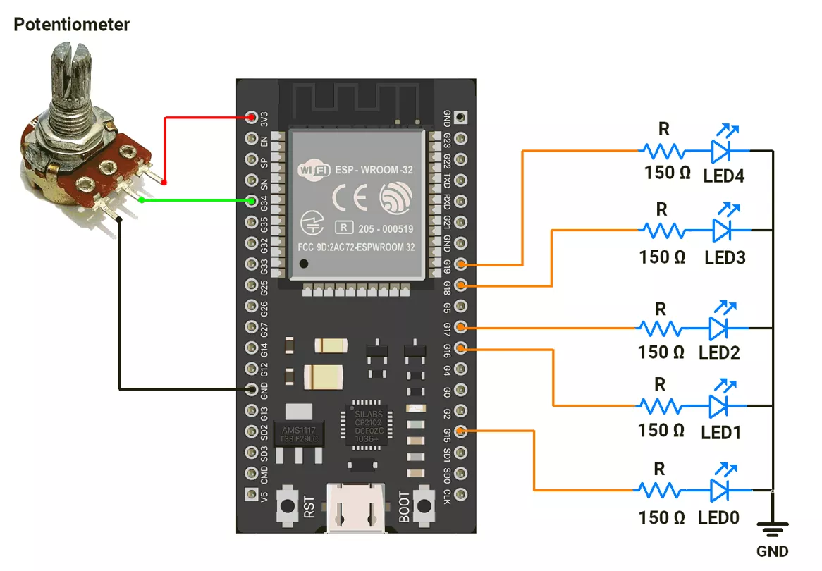
ESP32 Circuit Connection
- Connect the LEDs to GPIO pins 15, 16, 17, 18, and 19 with a 150 Ω resistor.
- Connect the potentiometer to the GPIO pin 34.
Circuit Diagram
ESP32 Firmware Implementation
Code
#define POT_PIN 34  // pin connected to Potentiometer

const uint8_t led_pin[] = { 15, 16, 17, 18, 19 };  // Pins connected to LEDs (PWM pins)

void setup() {
  // Set all LED pins as PWM outputs
  for (uint8_t i = 0; i < 5; i++) {
    ledcAttach(led_pin[i], 1000, 12);  // Attach pin with freq=1kHz, resolution=12-bit
    ledcWrite(led_pin[i], 0);          // Start with 0 duty
  }

  analogReadResolution(12);  // set ADC resolution
  Serial.begin(115200);
}

void loop() {
  uint16_t pot_value = analogRead(POT_PIN);  // Read the potentiometer ADC value (0–4095)
  uint16_t brightness;                       // To store brightness value

  // Divide the potentiometer range into 5 segments, one for each LED
  if (pot_value < 819) {
    // Segment 1: Potentiometer value 0–818
    ledcWrite(led_pin[1], 0);
    ledcWrite(led_pin[2], 0);
    ledcWrite(led_pin[3], 0);
    ledcWrite(led_pin[4], 0);

    brightness = map(pot_value, 0, 819, 0, 4095);
    ledcWrite(led_pin[0], brightness);
  } else if (pot_value < 1638) {
    // Segment 2: Potentiometer value 819–1638
    ledcWrite(led_pin[2], 0);
    ledcWrite(led_pin[3], 0);
    ledcWrite(led_pin[4], 0);
    ledcWrite(led_pin[0], 4095);

    brightness = map(pot_value, 819, 1638, 0, 4095);
    ledcWrite(led_pin[1], brightness);
  } else if (pot_value < 2457) {
    // Segment 3: Potentiometer value 1638–2457
    ledcWrite(led_pin[3], 0);
    ledcWrite(led_pin[4], 0);
    ledcWrite(led_pin[0], 4095);
    ledcWrite(led_pin[1], 4095);

    brightness = map(pot_value, 1638, 2457, 0, 4095);
    ledcWrite(led_pin[2], brightness);
  } else if (pot_value < 3276) {
    // Segment 4: Potentiometer value 2457–3276
    ledcWrite(led_pin[4], 0);
    ledcWrite(led_pin[0], 4095);
    ledcWrite(led_pin[1], 4095);
    ledcWrite(led_pin[2], 4095);

    brightness = map(pot_value, 2457, 3276, 0, 4095);
    ledcWrite(led_pin[3], brightness);
  } else {
    // Segment 5: Potentiometer value 3276–4095
    ledcWrite(led_pin[0], 4095);
    ledcWrite(led_pin[1], 4095);
    ledcWrite(led_pin[2], 4095);
    ledcWrite(led_pin[3], 4095);

    brightness = map(pot_value, 3276, 4095, 0, 4095);
    ledcWrite(led_pin[4], brightness);
  }
}
Code Explanation
- Potentiometer & ADC
- The potentiometer is read using:
uint16_t pot_value = analogRead(POT_PIN); - Since ADC resolution is set to 12-bit, this gives values from 0–4095.
- The potentiometer is read using:
- Division into 5 Parts
- The ADC range (0–4095) is split into 5 equal segments (~819 steps each). In that segment respective LED fades in and fades out.
- For example:
- 0–818 → LED1 fades in/out
- 819–1638 → LED2 fades in/out
- 1639 - 2457 → LED1 fades in/out
- 2458 - 3276 → LED1 fades in/out
- 3277 - 4095 → LED1 fades in/out
- PWM Brightness Control (12-bit)
- LEDs are controlled with 12-bit PWM (duty cycle 0–4095).
- Inside each segment, the potentiometer value is mapped to a PWM duty cycle:
- For example,
brightness = map(pot_value, 819, 1638, 0, 4095); - This means that as
pot_valuegoes from 819 → 1638, the PWM duty goes from 0 → 4095, smoothly fading the LED - The PWM value is then applied using:
ledcWrite(led_pin[1], brightness);
- LED Behavior
- Current LED → brightness goes up smoothly with map().
- Previous LEDs → forced to full brightness:
- Later LEDs → kept OFF.
- Overall Result
- As we turn the potentiometer:
- One LED fades in (0 → 4095 duty),
- All earlier LEDs stay fully ON (4095),
- All later LEDs stay OFF (0).
- As we turn the potentiometer:
- This creates a bar graph effect with smooth PWM transitions.
We are using the Arduino UNO development board and programming it using the Arduino IDE.
- Before uploading, make sure to select “Arduino UNO” as the board to ensure correct settings and compatibility.
The LEDs are connected to an Arduino UNO
In Arduino UNO, the PWM signal is generated using the analogWrite()
It has 6 PWM pins (3, 5, 6, 9, 10, 11) with 8-bit resolution (0–255) and fixed frequencies of ~490 Hz or ~976 Hz.
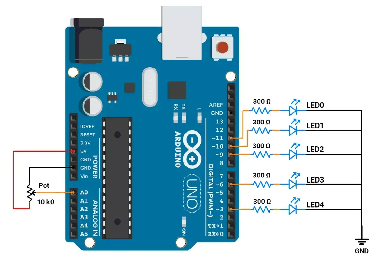
Arduino UNO Circuit connection
Let's connect,
- LED to GPIO pins 3,6,9,10, and 11 with 330Ω resistor.
- Potentiometer to GPIO pin A0.
Circuit Diagram
Arduino UNO Firmware Implementation
As we have 5 LEDs connected, the ADC range (0–1023) is divided into 5 equal segments, each corresponding to a specific LED.
ADC value Segmentation:
Let’s do ADC value segmentation, as we have 5 LEDs = 1023/5, i.e., 204.
- Segment 0 (ADC: 0–203):
- LED0’s brightness(PWM values) changes from 0 to 255 linearly as the ADC value changes from 0 to 203.
- LEDs 1, 2, 3, and 4 remain OFF during this segment.
- Segment 1 (ADC: 204–407):
- LED1’s brightness(PWM values) changes from 0 to 255 linearly as the ADC value changes from 204 to 407.
- LED0 remains fully ON (PWM = 255), while LEDs 2, 3, and 4 remain OFF.
- Segment 2 (ADC: 408–611):
- LED2’s brightness(PWM values) changes from 0 to 255 linearly as the ADC value changes from 408 to 611.
- LEDs 0 and 1 remain fully ON, while LEDs 3 and 4 remain OFF.
- Segment 3 (ADC: 612–815):
- LED3’s brightness(PWM values) changes from 0 to 255 linearly as the ADC value changes from 612 to 815.
- LEDs 0, 1, and 2 remain fully ON, while LED 4 remains OFF.
- Segment 4 (ADC: 816–1023):
- LED4’s brightness(PWM values) linearly changes from 0 to 255 as the ADC value changes from 816 to 1023.
- LEDs 0, 1, 2, and 3 remain fully ON.
Code(Method 1)
const int ledPins[] = { 11, 10, 9, 6, 3 };  // Pins connected to LEDs (PWM pins)

void setup() {
  // Set all LED pins as outputs
  for (int i = 0; i < 5; i++) {
    pinMode(ledPins[i], OUTPUT);
  }
}

void loop() {
  int potValue = analogRead(A0);  // Read the potentiometer ADC value (0–1023) connected to analog pin A0
  int brightness;                 //To store Brightness value
  // Divide the potentiometer range into 5 segments, one for each LED
  if (potValue < 204) {
    // Segment 1: Potentiometer value 0–203
    analogWrite(ledPins[1], 0);                  // Turn LED 1 fully OFF
    analogWrite(ledPins[2], 0);                  // Turn LED 2 fully OFF
    analogWrite(ledPins[3], 0);                  // Turn LED 3 fully OFF
    analogWrite(ledPins[4], 0);                  // Turn LED 4 fully OFF
    brightness = map(potValue, 0, 203, 0, 255);  // Map ADC value to PWM values
    analogWrite(ledPins[0], brightness);         // Control LED 0 brightness
  } else if (potValue < 408) {
    // Segment 2: Potentiometer value 204–407
    analogWrite(ledPins[2], 0);                    // Turn LED 2 fully OFF
    analogWrite(ledPins[3], 0);                    // Turn LED 3 fully OFF
    analogWrite(ledPins[4], 0);                    // Turn LED 4 fully OFF
    analogWrite(ledPins[0], 255);                  // Turn LED 0 fully ON
    brightness = map(potValue, 204, 407, 0, 255);  // Map ADC value to PWM values
    analogWrite(ledPins[1], brightness);           // Control LED 1 brightness (0% to 100%)
  } else if (potValue < 612) {
    // Segment 3: Potentiometer value 408–611
    analogWrite(ledPins[3], 0);                    // Turn LED 3 fully OFF
    analogWrite(ledPins[4], 0);                    // Turn LED 4 fully OFF
    analogWrite(ledPins[0], 255);                  // Turn LED 0 fully ON
    analogWrite(ledPins[1], 255);                  // Turn LED 1 fully ON
    brightness = map(potValue, 408, 611, 0, 255);  // Map ADC value to PWM values
    analogWrite(ledPins[2], brightness);           // Control LED 2 brightness (0% to 100%)
  } else if (potValue < 816) {
    // Segment 4: Potentiometer value 612–815
    analogWrite(ledPins[4], 0);                    // Turn LED 4 fully OFF
    analogWrite(ledPins[0], 255);                  // Turn LED 0 fully ON
    analogWrite(ledPins[1], 255);                  // Turn LED 1 fully ON
    analogWrite(ledPins[2], 255);                  // Turn LED 2 fully ON
    brightness = map(potValue, 612, 815, 0, 255);  // Map ADC value to PWM values
    analogWrite(ledPins[3], brightness);           // Control LED 3 brightness (0% to 100%)
  } else {
    // Segment 5: Potentiometer value 816–1023
    analogWrite(ledPins[0], 255);                   // Turn LED 0 fully ON
    analogWrite(ledPins[1], 255);                   // Turn LED 1 fully ON
    analogWrite(ledPins[2], 255);                   // Turn LED 2 fully ON
    analogWrite(ledPins[3], 255);                   // Turn LED 3 fully ON
    brightness = map(potValue, 816, 1023, 0, 255);  // Map ADC value to PWM values
    analogWrite(ledPins[4], brightness);            // Control LED 4 brightness (0% to 100%)
  }
}
Code(Method 2)
const int ledPins[] = { 11, 10, 9, 6, 3 };  // Pins connected to LEDs (PWM pins)

void setup() {
  // Set all LED pins as outputs
  for (int i = 0; i < 5; i++) {
    pinMode(ledPins[i], OUTPUT);
  }
}

void loop() {
  int potValue = analogRead(A0);    // Read potentiometer value (0–1023)
  int segment = potValue / 204;     // Determine which segment the value falls into (0–4)
  int brightness = potValue % 204;  // Get the remainder for brightness mapping in the segment

  // Smooth transition for LED brightness
  for (int i = 0; i < 5; i++) {
    if (i < segment) {
      analogWrite(ledPins[i], 255);  // Fully on LEDs in previous segments
    } else if (i == segment) {
      analogWrite(ledPins[i], map(brightness, 0, 203, 0, 255));  // Gradually vary brightness of current LED
    } else {
      analogWrite(ledPins[i], 0);  // Turn off LEDs in next segments
    }
  }

  // Short delay to stabilize transitions
  delay(10);
}
Code Explanation
Logic
- LEDs in earlier segments are fully ON.
- The current segment's LED brightness is gradually adjusted using map().
- LEDs in later segments are turned OFF explicitly.
Method 1: Explanation
- Approach: The potentiometer range is divided into five fixed segments using if and else-if conditions.
- Strengths: Simple to understand and implement.
- Weaknesses: Code is repetitive and less scalable.
- It is harder to extend for more LEDs or segments.
Method 2: Explanation
- Approach: The potentiometer range is dynamically divided into segments using integer division and a loop.
- Strengths: Compact, efficient, and scalable.
- Weaknesses: Slightly more complex for beginners to follow.
- Easy to extend for more LEDs or segments.
Output