54. I2C Scanner
In this task, we are implementing the I2C scanner using a microcontroller. It detects all connected I2C slave devices and displays their addresses over UART.
I2C Communication Basics
- Two-Wire Interface: Uses SDA (Serial Data Line) and SCL (Serial Clock Line).
- Master-Slave Architecture: The master initiates communication, while slaves respond when addressed.
- 7-Bit Addressing: Each slave device has a unique 7-bit address (0x08 to 0x77).
Note: When interfacing I²C devices operating at different voltages (e.g., 5 V ↔ 3.3 V), always use a voltage level shifter to ensure safe logic levels and reliable communication.
General Approach for I2C Scanning
- Initialize I2C and UART peripherals.
- Scan all possible I2C addresses (1 to 127).
- Check device presence using an acknowledgment signal.
- Report detected devices via UART.
Common Pitfalls & Tips
- Pull-up resistors: Ensure 4.7kΩ resistors are present on SDA & SCL lines.
- Clock speed: Ensure the I2C clock speed matches the slave device's specification.
So, by connecting and configuring the slave devices and the I2C communication, we can implement the task.
Below are the solutions to the given task using different microcontrollers
- STM32
- ESP32
- Arduino UNO
We’re using an STM32 NUCLEO-F103RB board as an I2C master, which operates at a 3.3V logic level.
Key Peripherals Used:
- I2C1: For I2C communication between the master and the slave.
- USART2: For serial communication with a serial terminal to display messages.
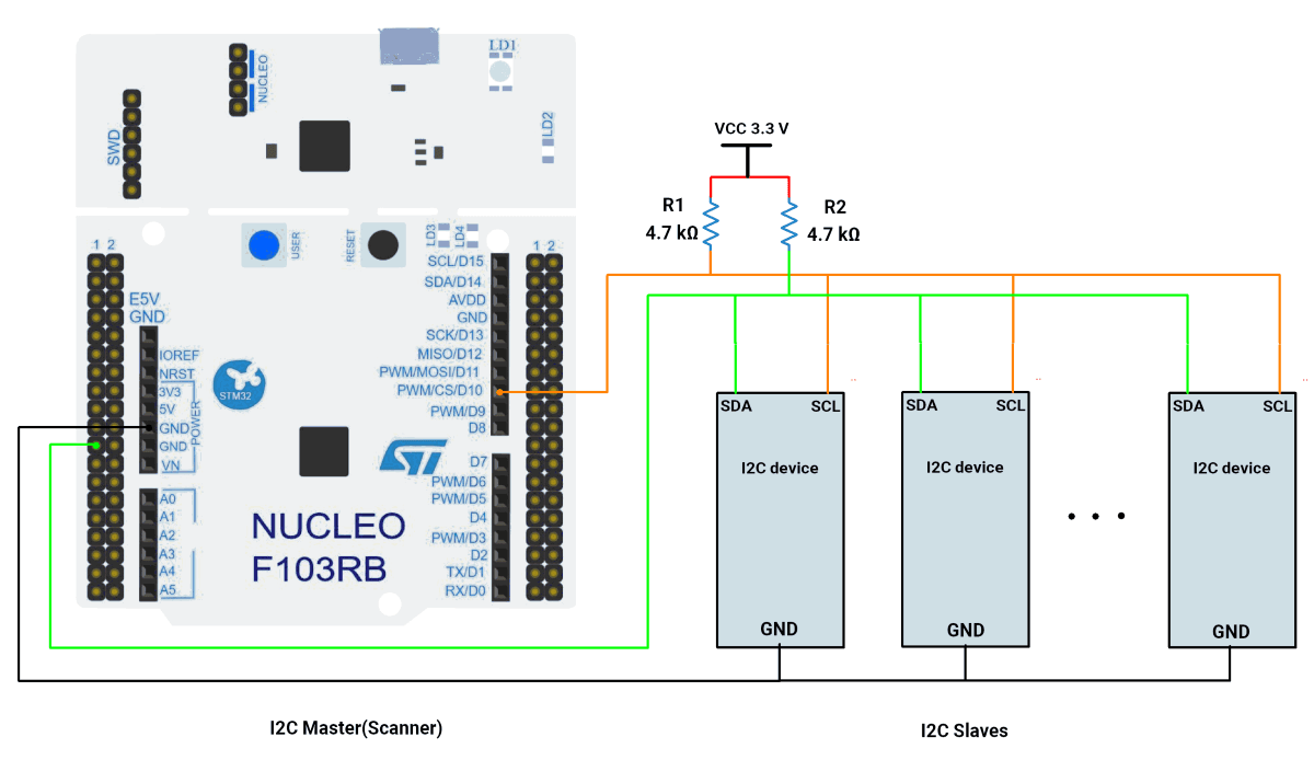
STM32 Hardware Connection
- Connect PB6 ➔ SCL of all slaves.
- Connect PB7 ➔ SDA of all slaves.
- Common every slave GND ➔ GND of the Nucleo.
- Connect 4.7 kΩ resistors between VCC and each of SDA & SCL.
- Connect the USB to the PC (power + UART).
Circuit Diagram
Firmware Implementation
Project Setup in STM32CubeIDE
- Create a Project
- Open STM32CubeIDE, start a new project, and select the NUCLEO-F103RB board.
- Basic Configuration (via CubeMX inside CubeIDE)
- Clock: Use the default HSI oscillator with PLL enabled (as configured in SystemClock_Config).
- GPIO: Enable clocks for PORTA, PORTB, PORTC, and PORTD.
- I2C1: I2C mode (Standard mode, 100kHz clock).
- USART2: Enabled at 115200 baud, 8-N-1.
- Code Generation
- CubeMX will automatically generate all the startup code, including:
HAL_Init()→ Initializes HAL and system tick.SystemClock_Config()→ Configures system clock (HSI + PLL).MX_GPIO_Init()→ Initializes GPIO ports.MX_USART2_UART_Init()→ Configures UART2.MX_I2C1_Init()→ Configures I2C1.
- This code sets up the hardware and prepares the project for firmware development, so we only need to add our application logic in the user code sections
- CubeMX will automatically generate all the startup code, including:
Code Snippets from main.c
I2C Initialization (MX_I2C1_Init)
hi2c1.Instance = I2C1;
hi2c1.Init.ClockSpeed = 100000;       // 100kHz
hi2c1.Init.DutyCycle = I2C_DUTYCYCLE_2;
hi2c1.Init.AddressingMode = I2C_ADDRESSINGMODE_7BIT;
if (HAL_I2C_Init(&hi2c1) != HAL_OK) {
  Error_Handler();
}- Initializes I2C1 peripheral with 100kHz clock speed, standard duty cycle, and 7-bit addressing mode.
UART Initialization (MX_USART2_UART_Init)
huart2.Instance = USART2;
huart2.Init.BaudRate = 115200;
if (HAL_UART_Init(&huart2) != HAL_OK) {
  Error_Handler();
}- Configures USART2 for UART communication at 115200 baud rate.
Header Includes
#include <string.h>
#include <stdio.h>- Includes standard libraries for string operations and formatted output.
Private Variables
uint8_t tx_data = 0;
uint8_t address;
uint8_t devices = 0;
HAL_StatusTypeDef status;- Declares variables for I2C transmission data, device address scanning, device count, and operation status.
Main Loop I2C Scanner Logic
The main scanning logic is implemented in the while(1) loop:
HAL_UART_Transmit(&huart2, (uint8_t*)"\n\rI2C Scanner \n\r\n\r", 18, HAL_MAX_DELAY);
HAL_Delay(10);
while (1) {
  devices = 0;
  HAL_UART_Transmit(&huart2, (uint8_t*)"Scanning...\n\r", 13, HAL_MAX_DELAY);

  for (address = 1; address <= 127; address++) {
    status = HAL_I2C_IsDeviceReady(&hi2c1, address << 1, 2, 2);


    if (status == HAL_OK) {
      char msg[40];
      int len = sprintf(msg, "I2C device found at address 0x%02X\n\r", address);
      HAL_UART_Transmit(&huart2, (uint8_t*)msg, len, HAL_MAX_DELAY);
      devices++;
    }
  }

  if (devices == 0) {
    HAL_UART_Transmit(&huart2, (uint8_t*)"No I2C devices found\n\r\n\r", 22, HAL_MAX_DELAY);
  } else {
    char msg[64];
    int len = sprintf(msg, "Total no. of slave devices connected are %d\n\r\n\r", devices);
    HAL_UART_Transmit(&huart2, (uint8_t*)msg, len, HAL_MAX_DELAY);
  }

  HAL_Delay(5000);
}
Scans all 127 possible I2C addresses every 5 seconds, transmits found devices' addresses via UART. Uses HAL_I2C_IsDeviceReady to check device presence and formats output messages.
Key HAL Functions Used
HAL_I2C_IsDeviceReady(): Checks if a device responds at a given address.HAL_UART_Transmit(): Sends scan results to a serial monitor.
Expected Output
When executed, the program outputs detected I2C devices via UART:
I2C Scanner
Scanning...
I2C device found at address 0x3C
Total no. of slave devices connected are: 1
Download Project
The complete STM32CubeIDE project (including .ioc configuration, main.c, and HAL files) is available here:
📥 Download Project
We are using the ESP32 DevKit v4 development board and programming it using the Arduino IDE.
- Before uploading, make sure to select “ESP32 Dev Module” as the board to ensure correct settings and compatibility.
Default I²C Pins Of ESP32
By default, the ESP32 Arduino core assigns:
- SDA → GPIO21
- SCL → GPIO22
In the given task, we used the default I²C Pins.
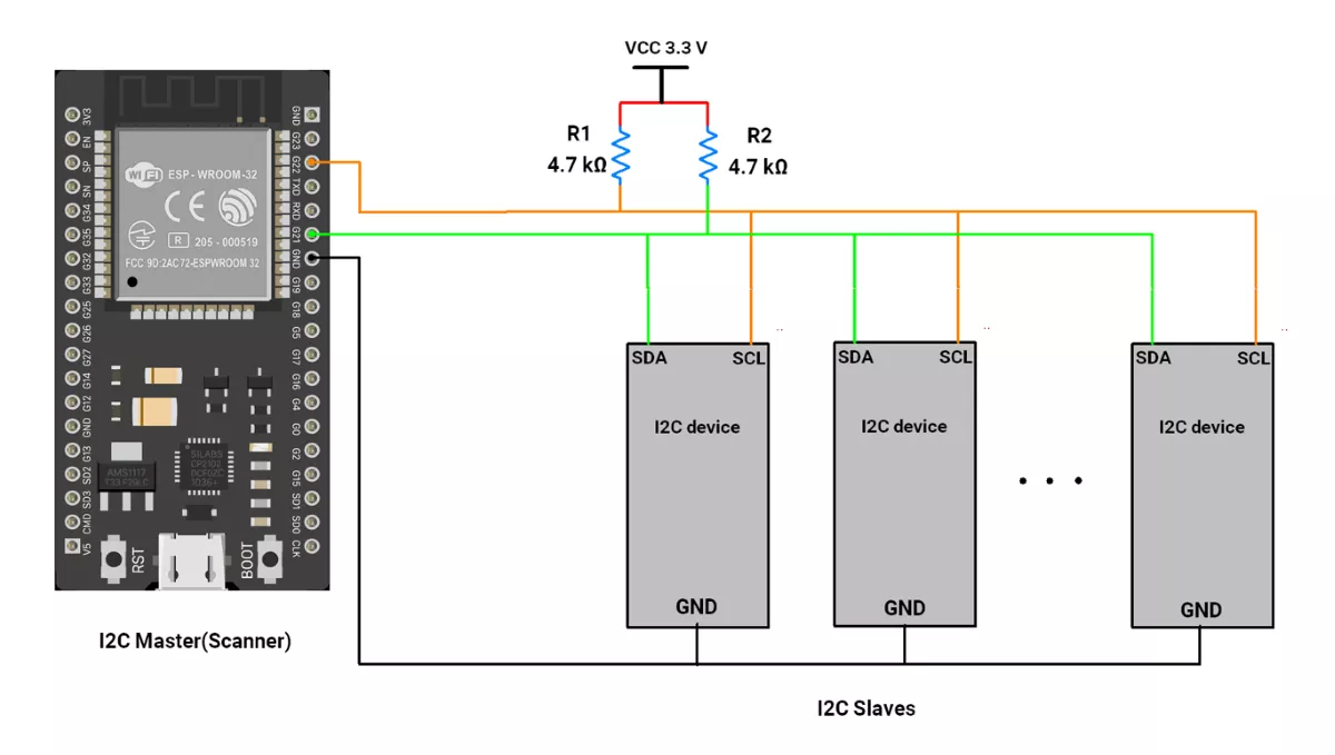
Hardware Connection
- Connect GPIO Pin 22➔ SCL of all slaves.
- Connect GPIO Pin 21➔ SDA of all slaves.
- Common every slave GND ➔ GND of the ESP32.
- Connect 4.7 kΩ resistors between VCC and each of SDA & SCL.
ESP32 Circuit Diagram
ESP32 as I2C Scanner Code
#include <Wire.h>   // Include I2C library

// Define I2C pins for ESP32
#define I2C_SDA 21   // Default SDA pin for ESP32
#define I2C_SCL 22   // Default SCL pin for ESP32

void setup() {
  // Start Serial Monitor for debugging
  Serial.begin(115200);
  delay(1000);  // Give Serial some time to initialize

  // Initialize I2C communication with custom SDA and SCL pins
  Wire.begin(I2C_SDA, I2C_SCL);

  Serial.println("\nESP32 I2C Scanner");
}

void loop() {
  byte error, address;   // Variables to hold I2C error code and device address
  int devices = 0;       // Counter for found devices

  Serial.println("Scanning I2C bus...");

  // Loop through all possible I2C addresses (1–126)
  for (address = 1; address < 127; address++) {
    // Try to start transmission with the current address
    Wire.beginTransmission(address);
    error = Wire.endTransmission();  // End transmission and capture error status

    if (error == 0) {
      // If no error, a device responded at this address
      Serial.print("I2C device found at address 0x");
      if (address < 16) Serial.print("0"); // Format leading zero for addresses < 0x10
      Serial.println(address, HEX);
      devices++;
    }
    else if (error == 4) {
      // Error code 4 means unknown error at this address
      Serial.print("Unknown error at address 0x");
      if (address < 16) Serial.print("0");
      Serial.println(address, HEX);
    }
  }

  // Print summary of scan results
  if (devices == 0) {
    Serial.println("No I2C devices found\n");
  } else {
    Serial.print("Total I2C devices found: ");
    Serial.println(devices);
    Serial.println("Scan complete\n");
  }

  delay(5000);  // Wait 5 seconds before scanning again
}
Code Explanation
- Setup
- Calls
Wire.begin(21, 22)→ sets up I²C on ESP32 default pins.
- Calls
- Loop (Scanner)
- For each possible I²C address (1–126):
- Sends a transmission request with
Wire.beginTransmission(address). - Checks
Wire.endTransmission()result:0→ Device responded → print address.4→ Unknown error → print error message.
- Sends a transmission request with
- After checking all addresses, it prints a summary of the devices found.
- For each possible I²C address (1–126):
- Wait
- Delays 5 seconds, then repeats the scan.
We are using the Arduino UNO development board and programming it using the Arduino IDE.
- Before uploading, make sure to select “Arduino UNO” as the board to ensure correct settings and compatibility.
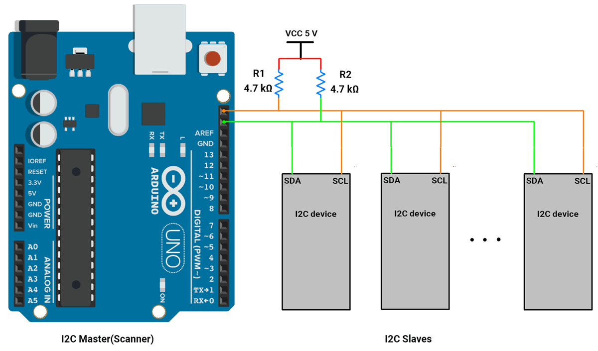
Arduino UNO Hardware Connection
- Connect A5 ➔ SCL of all slaves.
- Connect A4 ➔ SDA of all slaves.
- Common every slave GND ➔ GND of the Arduino UNO.
- Connect 4.7 kΩ resistors between VCC and each of SDA & SCL.
Circuit Connection
Arduino UNO as an I2C Scanner Code
#include <Wire.h>

void setup() {
  Wire.begin();                // Initialize I2C
  Serial.begin(115200);          // Initialize Serial communication
  Serial.println("\nI2C Scanner");
}

void loop() {
  byte error, address;
  int devices = 0;

  Serial.println("Scanning...");

  for (address = 1; address <= 127; address++) { // I2C addresses range from 1 to 127
    Wire.beginTransmission(address);
    error = Wire.endTransmission();

    if (error == 0) { // Device responded
      Serial.print("I2C device found at address 0x");
      if (address < 16) Serial.print("0");
      Serial.println(address, HEX);
      devices++;
    } else if (error == 4) {
      Serial.print("Unknown error at address 0x");
      if (address < 16) Serial.print("0");
      Serial.println(address, HEX);
    }
  }

  if (devices == 0) {
    Serial.println("No I2C devices found\n");
  } else {
    Serial.print("Total no. of slave devices connected are ");
    Serial.println(devices);
    Serial.println("Scan complete\n");
  }

  delay(5000); // Wait 5 seconds before scanning again
}
Code Explanation
- I2C Master Mode
- The Arduino Uno is set to act as an I2C master using the
Wire.begin()function.
- The Arduino Uno is set to act as an I2C master using the
- Address Scanning
- The code loops through all possible 7-bit I2C addresses (0x01 to 0x7F) and checks for acknowledgment using
Wire.beginTransmission()andWire.endTransmission().
- The code loops through all possible 7-bit I2C addresses (0x01 to 0x7F) and checks for acknowledgment using
- Error Handling
- If
Wire.endTransmission()returns 0, which means the slave responded successfully. - If it returns other error codes (e.g., 4), the error is logged to the Serial Monitor.
- If
- Serial Output
- The detected I2C slave addresses are displayed in hexadecimal format, and the total number of slave devices on the Serial Monitor.
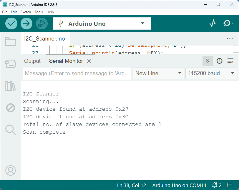
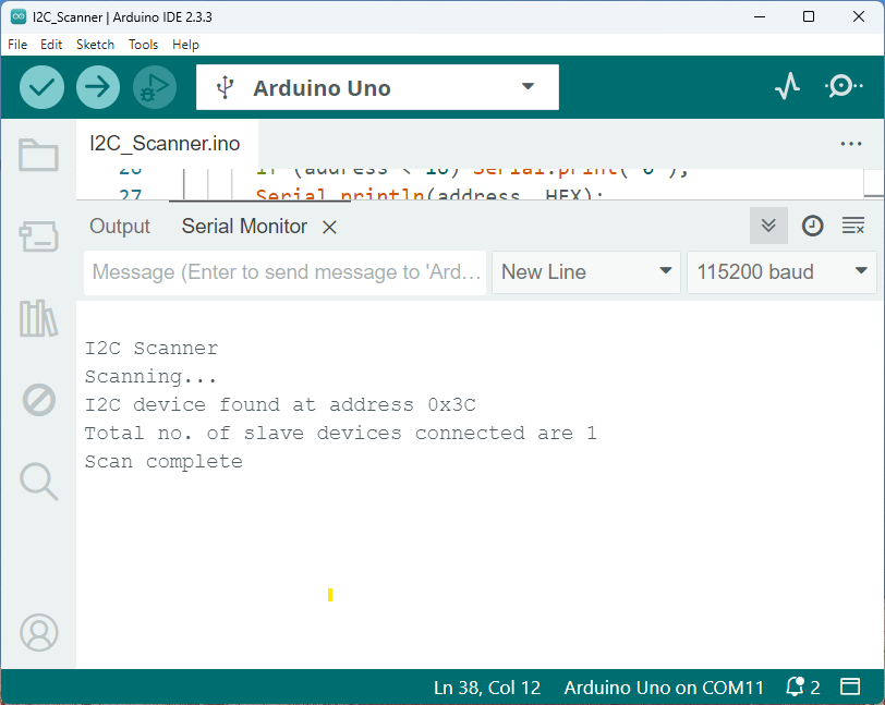
Output
Sample output with one slave device connected
Sample output with two slave devices connected