54. I2C Scanner
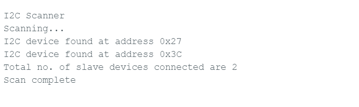
Build an I2C Address Scanner using a microcontroller to identify slave devices connected to the I2C bus. The program scans the bus, detects active slave addresses, and prints the detected addresses (in hexadecimal format) along with the total number of devices on the serial terminal (e.g., Putty, Arduino IDE).
Sample Example
Expected output when two I2C slave devices are connected,
I2C Basics
Two-wire communication protocol(Serial-synchronous)
- SDA (Serial Data Line) – Bidirectional data line.
- SCL (Serial Clock Line) – Clock signal generated by the master.
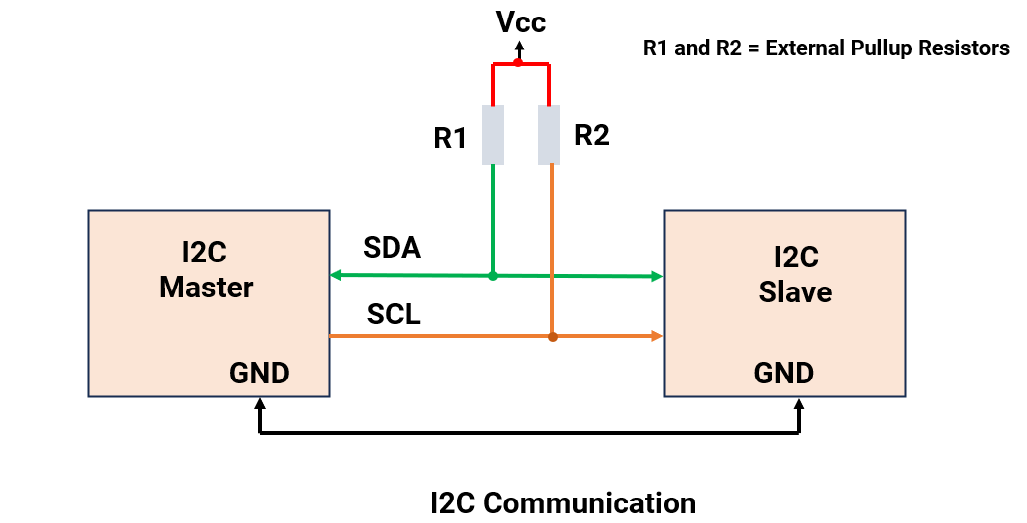
The master initiates communication always.
It is a Short-distance communication protocol with a distance of <10cm.
With I²C, multi-master and multi-slave or both at the same time are possible.
I²C communication is commonly used to interface such as LCDs, OLED displays, RTC modules, and various sensors.
I²C Communication
I²C Frame
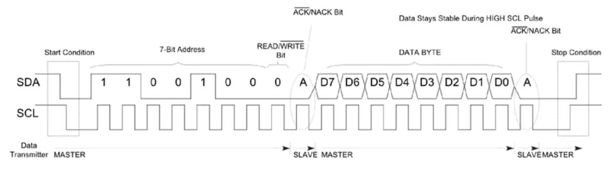
I²C Frame Description
| Frame | Description |
|---|---|
| Star Condition | SCL = HIGH, SDA = HIGH → LOW |
| 7-Bit Address | Slave address sent by master (7 bits). |
| Read/ Write bit | 0 = Write to slave 1 = Read from slave |
| ACK/NACK bit | 0 = ACK (address received) 1 = NACK (Not received) |
| Data Byte | 8 bits of data (read/write). |
| ACK/NACK bit | 0 = ACK (Data received) 1 = NACK (Data not Received) |
| Stop Condition | SCL = HIGH, SDA = LOW → HIGH (End of Communication) |
Note: SDA never changes when SCL is HIGH. If it changes, it will be either a start or stop condition.
Example frames
1.I²C master writing data (0x65) to slave (address = 0x35)

2. I²C master reading data (0x66) from slave (address = 0x08)

Note: 1) Data direction → MSB to LSB (MSB 1st)
2) The ideal state of SCL and SDA is HIGH.
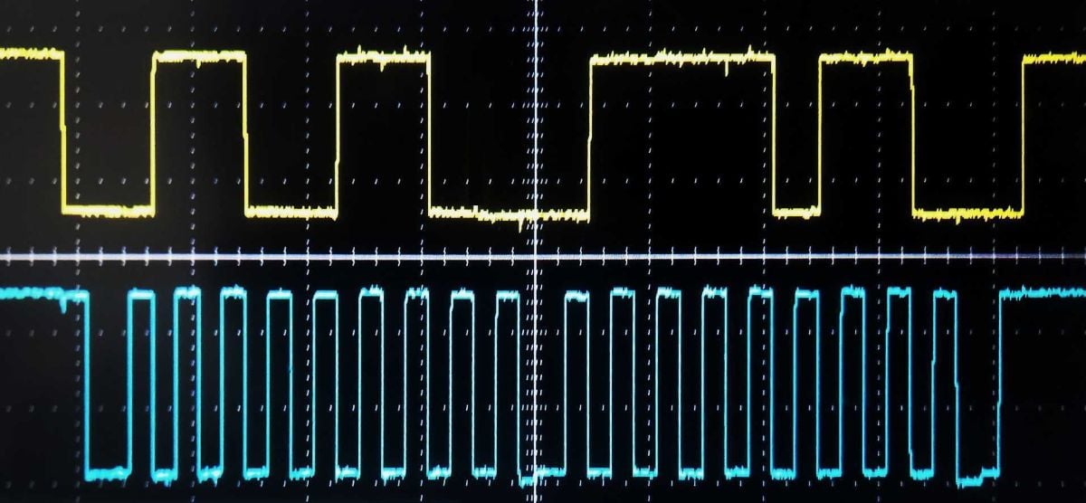
3. DSO output of I²C master sending 0x7B to slave at address 0x33.

DSO Output
Pull-up in I²C Communication
- SDA and SCL use open-drain connections.
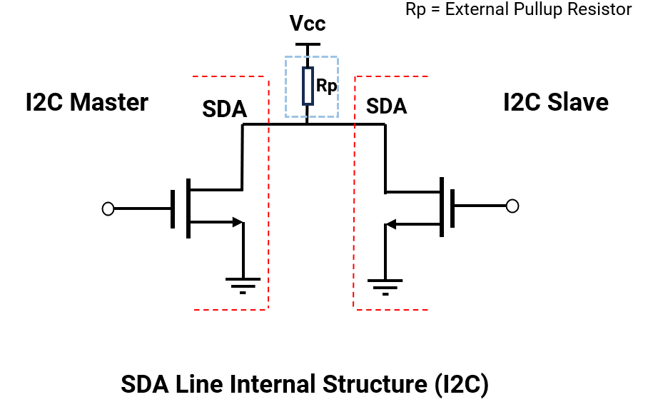
- Open drain Output→ I²C devices can only pull the bus LOW. They cannot drive HIGH actively.
- To pull the line High actively → An Internal / External Pull-up needs to be used. Without it, the bus floats and gives garbage data.
- Pull-up resistor can be from 1kΩ to 10kΩ. For long distances or high speeds, use a lower value resistor.
I²C Modes
I²C modes are defined based on communication speed. Most of the sensors come with only the standard mode.
| Modes | Maximum Bit Rate |
|---|---|
| Standard Mode | 100 kbps |
| Fast Mode | 400 kbps |
| Fast Mode Plus | 1 Mbps |
| High-Speed Mode | 3.4 Mbps |
| Ultra-Fast-Mode | 5 Mbps |
I²C Addressing (7-bit Address)
Generally, addresses from 0x00 to 0x07 are reserved for special purposes.
Address (0x00): It is used to broadcast a message sent to all slave devices, known as a General Call.
I²C Clock Stretching
A slave device can pause communication by holding the SCL clock line LOW to force the master to wait.
Gives slaves time to:
- Process received data
- Prepare data to send
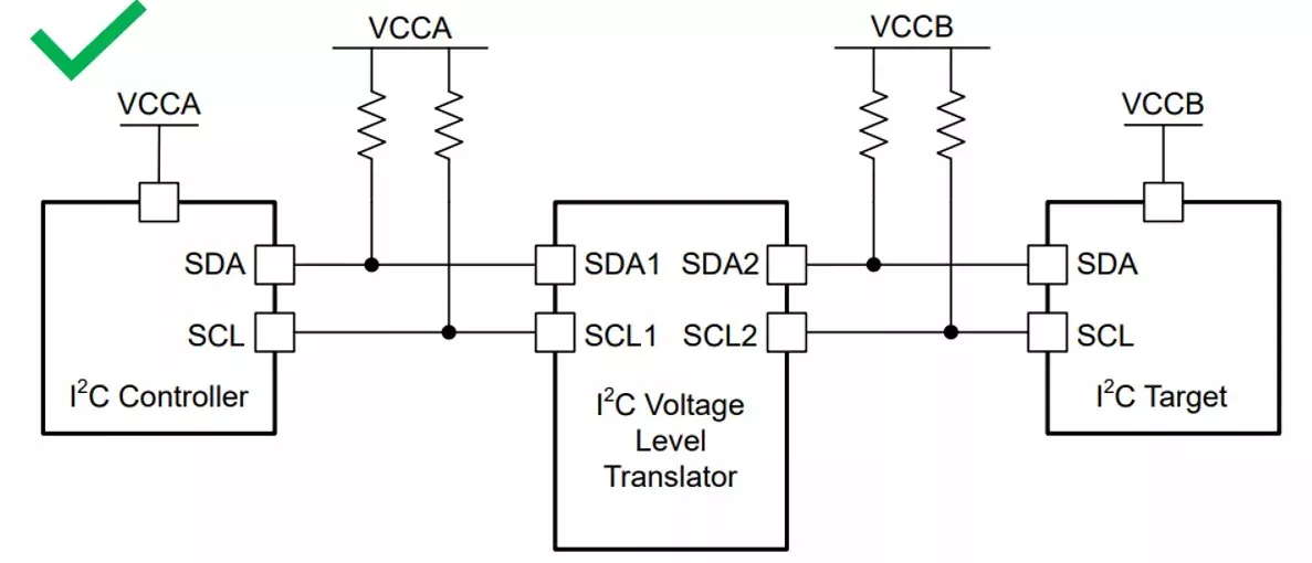
I²C Voltage Level Mismatch
Mixed voltages (e.g., 3.3V MCU ↔ 5V sensor) can result in invalid logic levels and can damage devices (overvoltage on I/O pins).
To avoid this, a bidirectional level shifter or I²C buffer with voltage translation can be used.
I²C Arbitration
In multi-master I²C, when both masters try to initiate communication at the same time instance, then the master that transmits a ZERO (LOW ) bit first gets control of the I²C bus.
Why: Since the Master transmitting ZERO (LOW) will force the SDA line to LOW, although the other master tries to send ONE (HIGH).
Example
Master 1: 0xB2 → 10110010
Master 2: 0xB4 → 10110100
Bus matches for 5 bits, at bit-6, master-1 wins and continues.
(Note : In I2C on data line, transmission starts with MSB first.)
I²C in Micro-Controllers
As an important on-board communication protocol, I²C is always present in most of the controllers, i.e., AVR, PIC, ARM, and RISC.
Generally following registers are present in controllers. (with reference to AVR ATmega 328P- also known as TWI (Two-Wire Interface)).
| Registers | Description |
|---|---|
| TWBR | I²C Bit Rate Register: sets the I²C clock frequency |
| TWCR | I²C Control Register: manages interrupts, enables the interface, and controls acknowledgment and start/stop conditions. |
| TWSR | I²C Status Register: Stores the status code of the I²C (TWI) bus after each operation, sets the clock divider for I²C. |
| TWDR | I²C Data buffer: holds the data to be transmitted or the data received via I²C (TWI) |
| TWAR | I²C Address Register: stores the slave address, enables response to general call address. |
Writing I²C Driver (Master- Writing Data to slave)
- Set Bitrate - Set the prescaler and desired I²C bitrate.
- Send Start Condition - Set the bits in the control register to initiate the start condition.
- Wait for TWI0NT- wait for action to perform.
- Send Slave Address + Write Bit .
- Wait for TWINT - wait for action to perform
- Send a Data Byte to the slave.
- Wait for TWINT -wait for action to perform.
- Send Stop Condition - Stop I²C & bus release.
I²C in Arduino Uno (ATmega328P)
I²C communication pins in Arduino UNO
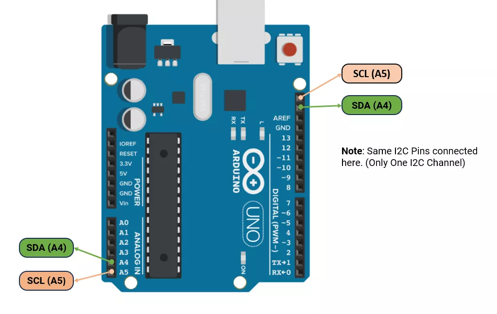
Arduino I²C (Wire Library) Functions
In Arduino UNO, the Wire.h library is used for I²C.
The default speed is 100 kHz, but it can be changed to 400 kHz.
| Function | Description |
|---|---|
Wire.begin() | Initialize I²C as master |
Wire.begin(address) | Initialize I²C as slave with address |
Wire.setClock(frequency) | Set I²C speed (Hz) |
Wire.beginTransmission(address) | Start communication with a slave device |
Wire.write(data) | Send data to buffer. |
Wire.endTransmission() | Ends transmission started by beginTransmission() and sends all queued bytes to the device. |
Wire.requestFrom(address, len) | Request bytes from a slave |
Wire.available() | Check if data is received |
Wire.read() | Read received byte |
Wire.onReceive(handler) | Set callback for received data |
Wire.onRequest(handler) | Set callback for data requests |
Example
Send character ‘A’ from master( Arduino UNO) to slave 0x08 (Arduino UNO) after every 1 second.
Master Code
#include <Wire.h>
void setup() {
  Wire.begin(); // Initialize  I²C as master
}
void loop() {
  Wire.beginTransmission(0x08);  // Slave address 0x08
  Wire.write('A'); // Send character
  Wire.endTransmission();
  delay(1000);
}
Slave Code
#include <Wire.h>
void setup() {
  Serial.begin(9600); // initialize the serial communication
  Wire.begin(0x08);  // Initialize I2C in slave mode
  Wire.onReceive(receiveEvent);  // Register callback
}
void loop() {
}
// Callback function definition
void receiveEvent(int bytesReceived) {
  if (Wire.available()) {
    char receiveData = Wire.read(); // read the received data from master
    // display data received from master
    Serial.print(receiveData);
  }
}