17. LED Brightness Control Using Potentiometer
Analyzing the task above, we need to vary the LED's brightness as the potentiometer rotates
To control LED brightness, both the potentiometer and the LED must be properly interfaced with the microcontroller. Here’s how this is typically done:
Potentiometer & LED Interfacing
Potentiometer Interfacing
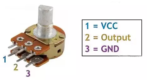
- Connection: Connect the potentiometer terminals 1 and 3 to VCC and GND or vice versa. Terminal 2 (wiper) to the MCU ADC pin.
Note: We can use any of the potentiometers with values between 1kΩ and 10kΩ.
LED Interfacing
- Connection:
- Connect the microcontroller’s PWM-capable GPIO pin to the LED anode, the cathode to one end of a current-limiting resistor, and the other end of the resistor to GND.
- Function:
- The microcontroller reads the potentiometer’s ADC value, maps it to a PWM duty cycle, and adjusts the LED brightness smoothly as the knob is turned.
Calculating the current-limited Resistor Value
Case 1: 5V Supply
- LED forward voltage (Vf) = 1.8V (from datasheet)
- Voltage across resistor (VR) = Supply voltage – Vf = 5V – 1.8V = 3.2V
- Resistor value (R) = VR / I = 3.2V / 10 mA = 320 Ω
Standard resistor values near 320 Ω: 330 Ω or 300 Ω (whichever is available).
Similarly, Case 2: 3.3V Supply
- Voltage across resistor (VR) = 3.3V – 1.8V = 1.5V
- Resistor value (R) = 1.5V / 10 mA = 150 Ω
Standard resistor value: 150 Ω.
So, by selecting a proper resistor, LED, and potentiometer, we can implement the task.
Below are the solutions to the given task using different microcontrollers
- STM32
- ESP32
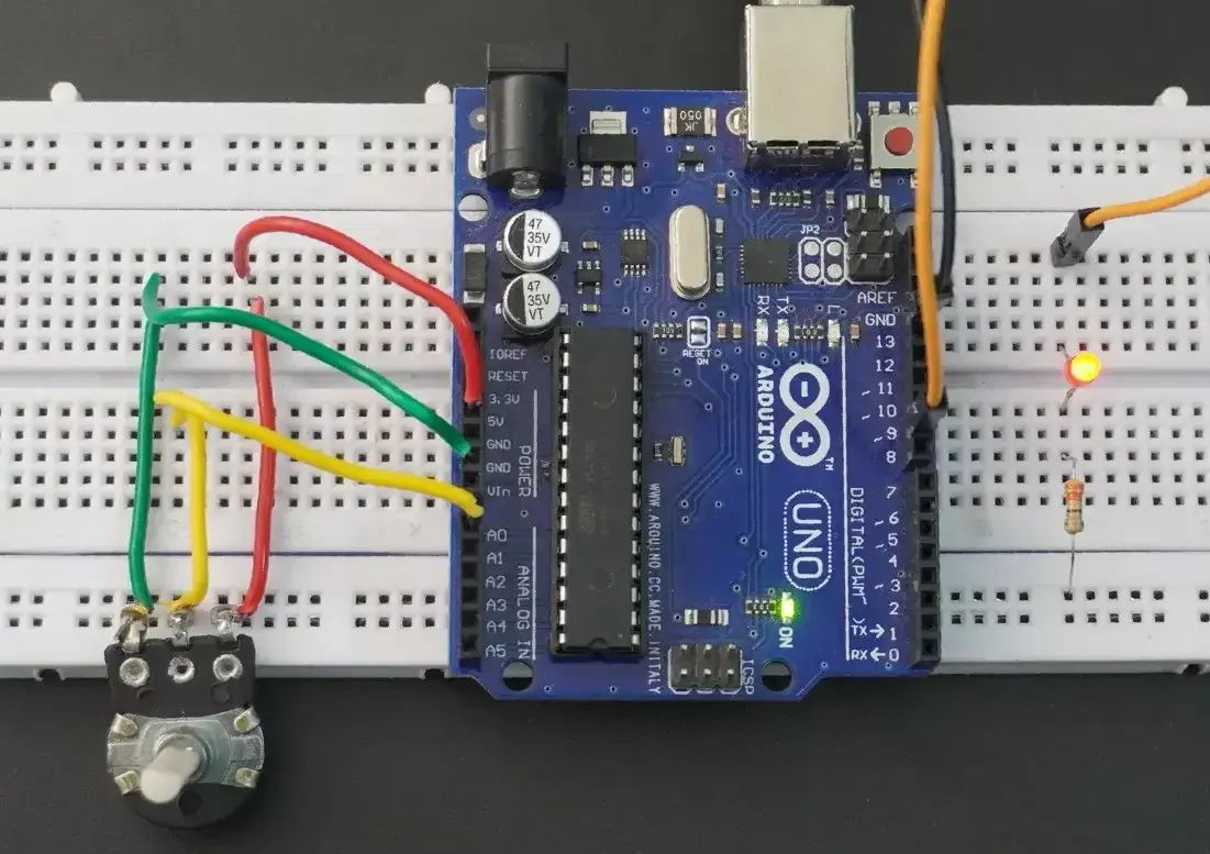
- Arduino UNO
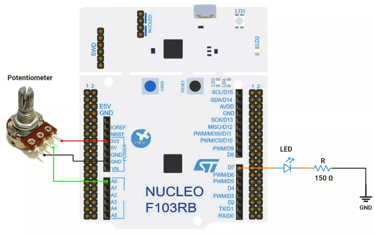
We’re using an STM32 NUCLEO-F103RB board, which runs at a 3.3V logic level.
Key Peripherals Used
- ADC1(PA0): Reads analog voltage from the potentiometer.
- TIM1 Channel 1 (PA8): PWM output for LED brightness control
- GPIO: PA8 configured as alternate function for PWM output
- Optional USART2: For serial debugging (configured, not used here)
STM32 Hardware Connection
- Potentiometer Setup:
- Connect the potentiometer’s middle pin to PA0 (ADC1_IN0) for analog input.
- Connect the other two pins to 3.3V (VCC) and GND (for voltage division).
- (Use a 10kΩ potentiometer for best results.)
- LED Setup:
- PWM Output Pin: PA8 (TIM1 CH1).
- Connect the LED anode (long leg) to PA8.
- Connect the LED cathode (short leg) via a 150Ω resistor to GND.
Circuit Diagram
STM32 Firmware Implementation
Project Setup in STM32CubeIDE
- Create a Project
Open STM32CubeIDE, start a new project, and select the NUCLEO-F103RB board. - Basic Configuration (via CubeMX inside CubeIDE)
- Clock: Use the default HSI oscillator with PLL enabled (as set in
SystemClock_Config). - GPIO:
- Configure PA8 as TIM1 Channel 1 PWM output (Alternate Function Push-Pull).
- ADC input channel IN0 (PA0) enabled for potentiometer/analog input.
- Timer 1 (TIM1 – PWM Generator):
- Prescaler = 1 → Timer clock = APB2 / 2.
- Period (ARR) = 4095 → Matches 12-bit ADC range for 1:1 mapping of ADC value to duty cycle.
- PWM mode enabled on Channel 1.
- ADC1 (Analog Input – PA0):
- Configured as single conversion, software triggered, 12-bit resolution.
- Right-aligned result, single channel (Channel 0).
- USART2 (Debugging/Expansion):
- Enabled at 115200 baud, 8-N-1.
- Clock: Use the default HSI oscillator with PLL enabled (as set in
- Code Generation
- CubeMX will automatically generate all the startup code, including:
HAL_Init()→ Initializes the HAL library.SystemClock_Config()→ Configures system clock (HSI + PLL).MX_GPIO_Init()→ Initializes GPIO clocks.MX_USART2_UART_Init()→ Configures USART2.MX_ADC1_Init()→ Initializes ADC1 on Channel 0.MX_TIM1_Init()→ Initializes TIM1 for PWM generation.
- This code sets up the hardware and prepares the project for firmware development, so we only need to add our application logic in the user code sections
Code Snippets from main.c
PWM control (TIM1 configurations)
static void MX_TIM1_Init(void) {
  htim1.Instance = TIM1;
  htim1.Init.Prescaler = 1;
  htim1.Init.CounterMode = TIM_COUNTERMODE_UP;
  htim1.Init.Period = 4095;  // ARR value
  // ... other configurations
}
TIM1 is configured as a PWM output:
- Prescaler = 1 (minimum division)
- Period = 4095 (ARR value)
- This gives a PWM resolution of 4096 steps
ADC configuration
static void MX_ADC1_Init(void) {
  ADC_ChannelConfTypeDef sConfig = { 0 };

  hadc1.Instance = ADC1;
  hadc1.Init.ScanConvMode = ADC_SCAN_DISABLE;
  hadc1.Init.ContinuousConvMode = DISABLE;
  hadc1.Init.DiscontinuousConvMode = DISABLE;
  hadc1.Init.ExternalTrigConv = ADC_SOFTWARE_START;
  hadc1.Init.DataAlign = ADC_DATAALIGN_RIGHT;
  hadc1.Init.NbrOfConversion = 1;
  if (HAL_ADC_Init(&hadc1) != HAL_OK) {
    Error_Handler();
  }

  sConfig.Channel = ADC_CHANNEL_0;
  sConfig.Rank = ADC_REGULAR_RANK_1;
  sConfig.SamplingTime = ADC_SAMPLETIME_13CYCLES_5;
  if (HAL_ADC_ConfigChannel(&hadc1, &sConfig) != HAL_OK) {
    Error_Handler();
  }
}
This initializes the ADC1 channel 0.
Main Firmware Logic
int main(void) {

  /* Reset of all peripherals, Initializes the Flash interface and the Systick. */
  HAL_Init();

  /* Configure the system clock */
  SystemClock_Config();

  /* Initialize all configured peripherals */
  MX_GPIO_Init();
  MX_USART2_UART_Init();
  MX_ADC1_Init();
  MX_TIM1_Init();

  // Start PWM generation on Timer 1, Channel 1
  // This enables the PWM output on the specified timer channel
  HAL_TIM_PWM_Start(&htim1, TIM_CHANNEL_1);

  while (1) {
    // Start ADC conversion
    HAL_ADC_Start(&hadc1);

    // Wait for ADC conversion to complete with a timeout of 20ms
    HAL_ADC_PollForConversion(&hadc1, 20);

    // Read the converted ADC value (0-4095 for 12-bit ADC)
    uint16_t adcValue = HAL_ADC_GetValue(&hadc1);

    // Update PWM duty cycle based on ADC reading
    // This creates a direct relationship between analog input and PWM output
    __HAL_TIM_SET_COMPARE(&htim1, TIM_CHANNEL_1, adcValue);

    // Small delay to stabilize the system and prevent overwhelming the ADC
    HAL_Delay(1);
  }
}- Initialization:
HAL_Init(): Initializes hardware abstraction layer (HAL) libraries.SystemClock_Config(): Sets up the system clock (CPU speed).- Peripheral Initialization: Configures GPIO, UART (for debugging), ADC (for analog input), and Timer 1 (for PWM generation).
- PWM Start: Enables PWM output on Timer 1, Channel 1.
- Main Loop (Runs Forever):
- Read ADC: Starts an analog-to-digital conversion (e.g., from a potentiometer or sensor).
- Wait for ADC Result: Polls until the conversion finishes (timeout: 20ms).
- Update PWM Duty Cycle: Sets the PWM pulse width based on the ADC value (0–4095 for 12-bit ADC).
- Higher ADC value → Longer PWM pulse (brighter LED, faster motor, etc.).
- Small Delay: 1ms pause to stabilize the system before the next read.
Download Project
The complete STM32CubeIDE project (including .ioc configuration, main.c, and HAL files) is available here
📥Download Project
We are using the ESP32 DevKit v4 development board and programming it using the Arduino IDE.
- Before uploading, make sure to select “ESP32 Dev Module” as the board to ensure correct settings and compatibility.
PWM Options on ESP32
- analogWrite()
- LEDC Peripheral
- MCPWM Peripheral
- Sigma-Delta Modulator
- RMT Peripheral
- General-Purpose Timers
Among these, the LEDC (LED Controller) peripheral is a dedicated hardware PWM controller, optimized for applications like LED brightness control, and we will use it in this task.
Pins to Avoid for PWM on ESP32
- GPIO6–11 → Used for flash memory
- GPIO34–39 → Input-only pins (not suitable for PWM output)
- GPIO0, GPIO2, GPIO15 → Strapping pins (affect boot mode)
- EN, SENSOR_VP, SENSOR_VN → Reserved for special functions
Important Note
In Arduino Core v2.x for ESP32, LEDC API functions like ledcSetup() and ledcAttachPin() are used for PWM configuration.
In Arduino Core v3.x, these functions are removed to avoid compilation errors, use the updated LEDC API instead; otherwise, you will encounter a compilation error. e.g.:
ledcAttach(pin, freq, resolution);ledcWrite(channel, dutyCycle);
Reference: ESP32 Arduino Core 2.x → 3.0 Migration Guide
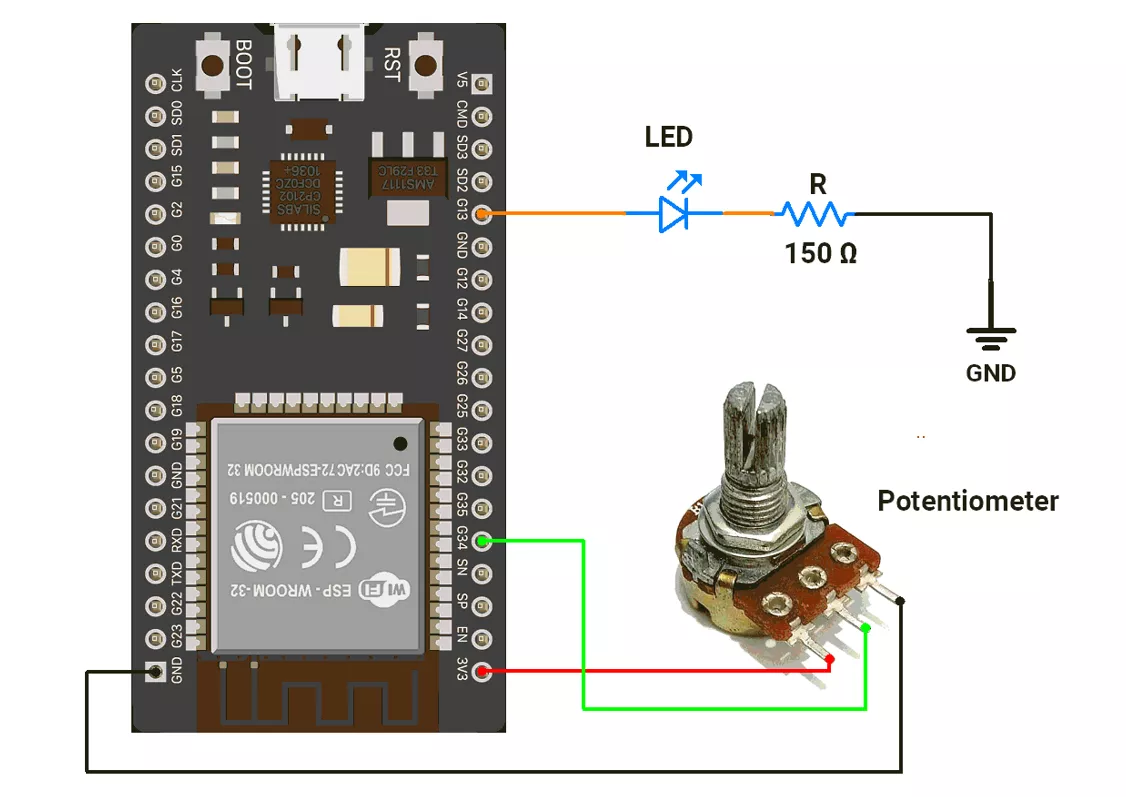
ESP32 Circuit Connection
- Connect the LED to GPIO pin 13 with a 150Ω resistor.
- Connect the potentiometer to the GPIO pin 34.
Circuit Diagram
ESP32 Firmware Implementation
Code
#define LED_PIN 14
#define POT_PIN 34

void setup() {
  Serial.begin(115200);

  // Attach the LED pin with PWM frequency 1 kHz and 12-bit resolution
  ledcAttach(LED_PIN, 1000, 12);

  // Set ADC resolution to 12 bits (0–4095)
  analogReadResolution(12);

  // Start with LED OFF (duty = 0)
  ledcWrite(LED_PIN, 0);
}

void loop() {
  // Read the potentiometer value (0–4095 for 12-bit ADC)
  int pot_value = analogRead(POT_PIN);

  // Write the ADC value directly as PWM duty cycle (0–4095)
  ledcWrite(LED_PIN, pot_value);

  delay(1);  // Small delay for stability
}
We are using the Arduino UNO development board and programming it using the Arduino IDE.
- Before uploading, make sure to select “Arduino UNO” as the board to ensure correct settings and compatibility.
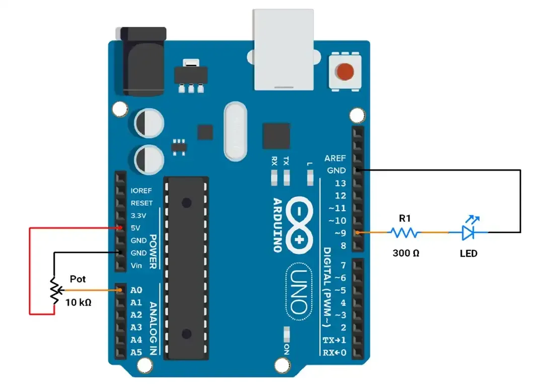
Arduino UNO Circuit Connection
- Connect the LED to GPIO pin 9 with a 330 Ω resistor.
- Connect the Potentiometer with GPIO pin A0.
Arduino UNO Firmware Implementation
In Arduino UNO, we have to control LED brightness using PWM(8-bit) by providing values from 0 to 255.
ADC (10-bit) will provide us with the value from 0 to 1023, so we need to map the ADC value to the PWM brightness value.
To map the ADC value with PWM, we are going to use two methods.
Method-1
We can do it by using the default function map();
We can provide the ADC and PWM ranges, so this function returns the proper mapping value accordingly.
Code(Method 1):
#define POT_PIN A0  // potentiometer is connected to A0 pin
#define LED_PIN 9   // LED is connected to pin no.9

void setup() {
  pinMode(LED_PIN , OUTPUT);  // Set the LED pin as an output
}

void loop() {
  int adcValue = analogRead(POT_PIN);  // Read the analog value from pin A0 (range: 0–1023)

  // Read the potentiometer value (0-1023) and map it to the PWM range (0-255)
  int brightness = map(adcValue, 0, 1023, 0, 255);

  // Adjust the LED brightness
  analogWrite(LED_PIN, brightness);
}
So as we can see, in the above map function, we have passed a total of 5 parameters, from which the ADC_value will be converted from Range (0-1023) to (0-255).
Method-2
We can calculate the mapping factor,
Mapping Factor = ADC Value / corresponding PWM value
= 1024 / 256
= 4
So whatever ADC value we receive, dividing it by 4 will give us the corresponding PWM value.
Code(Method 2):
#define POT_PIN A0  // potentiometer is connected to A0 pin
#define LED_PIN 9   // LED is connected to pin no.9


void setup() {
  pinMode(LED_PIN, OUTPUT);  // Configure pin 9 as an output to control the LED
}

void loop() {
  // Read the analog value from pin A0 (range: 0–1023)
  // The potentiometer adjusts this value based on its position
  int adcValue = analogRead(POT_PIN);

  // Map the potentiometer value (0–1023) to the PWM range (0–255)
  // Dividing by 4 is equivalent to the mapping (1023 / 255 = ~4)
  int brightness = adcValue / 4;

  // Write the mapped brightness value to the LED
  // This controls the LED brightness proportionally to the potentiometer position
  analogWrite(LED_PIN, brightness);
}
Output