16. LED Brightness Control Using PWM
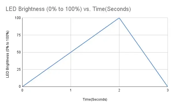
Analyzing the task above, we need to vary the LED's brightness over specific time intervals.
As we know, PWM (Pulse Width Modulation) is used to control LED brightness.
Also, we have to vary the LED brightness from 0% to 100% in 2 seconds, then from 100% back to 0% in 1 second.
To vary LED brightness smoothly using PWM with N discrete steps (e.g., 256 steps for 8-bit PWM), calculate the delay per brightness step as:
- Rise delay per step = (Total rise time) ÷ (Number of PWM steps)
- Fall delay per step = (Total fall time) ÷ (Number of PWM steps)
Examples:
- With 256 PWM steps:
- Rise delay per step = 2 seconds ÷ 256 ≈ 7.8125 milliseconds
- Fall delay per step = 1 second ÷ 256 ≈ 3.906 milliseconds
- With 10,000 PWM steps:
- Rise delay per step = 2 seconds ÷ 10,000 ≈ 200 microseconds
- Fall delay per step = 1 second ÷ 10,000 ≈ 100 microseconds
- With 4096 PWM steps:
- Rise delay per step = 2 seconds ÷ 4096 ≈ 488.281 microseconds
- Fall delay per step = 1 second ÷ 4096 ≈ 244.140 microseconds
Avoid flickering of LED: Human eyes can detect flicker below ~100 Hz. Always use a PWM frequency above 200 Hz (commonly 500 Hz–1 kHz for LEDs).
Hardware Connection
- We can connect the LED to any PWM pin.
- A 3 mm red LED has a forward voltage of about 1.8 V, and to safely allow around 10 mA current, the LED must be connected with a proper series resistor.
Calculating the Resistor Value
Case 1: 5V Supply
- LED forward voltage (Vf) = 1.8V (from datasheet)
- Voltage across resistor (VR) = Supply voltage – Vf = 5V – 1.8V = 3.2V
- Resistor value (R) = VR / I = 3.2V / 10 mA = 320 Ω
Standard resistor values near 320 Ω: 330 Ω or 300 Ω (whichever is available).
Similarly, Case 2: 3.3V Supply
- Voltage across resistor (VR) = 3.3V – 1.8V = 1.5V
- Resistor value (R) = 1.5V / 10 mA = 150 Ω
Standard resistor value: 150 Ω.
So, by selecting a proper resistor, LED, and calculating the delay correctly, we can implement the task.
Below are the solutions to the given task using different microcontrollers
- STM32
- ESP32
- Arduino UNO
We’re using an STM32 NUCLEO-F103RB board, which runs at a 3.3V logic level.
Key Peripherals Used
- TIM1 Channel 1 (PA8): PWM output for LED brightness control
- TIM4: Basic timer to generate controlled timing intervals
- GPIO: PA8 configured as alternate function for PWM output
- Optional USART2: For serial debugging (configured, not used here)
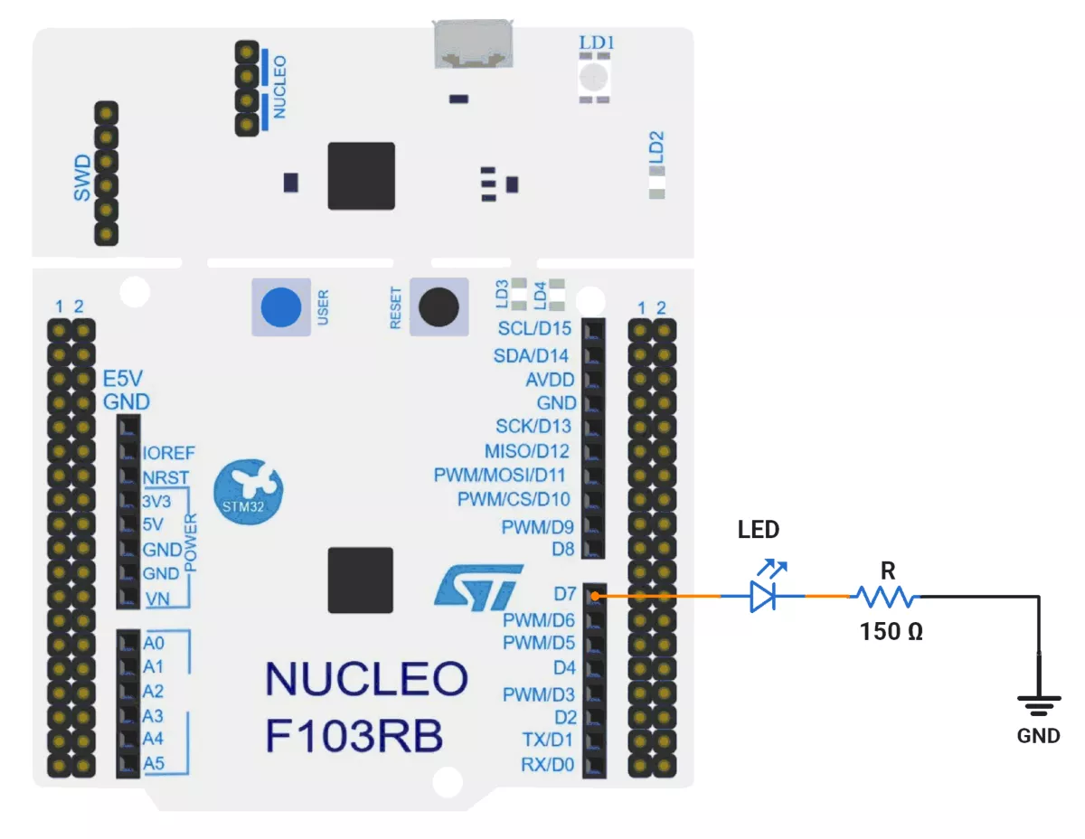
STM32 Hardware Connection
- Identify PWM output pin: PA8 (TIM1 CH1)
- Connect the LED anode (long leg) to PA8.
- Connect the LED cathode (short leg) via a 150Ω resistor to GND on the Nucleo board.
Circuit Diagram
STM32 Firmware Implementation
Project Setup in STM32CubeIDE:
- Create a Project
- Open STM32CubeIDE, start a new project, and select the NUCLEO-F103RB board.
- Basic Configuration (via CubeMX inside CubeIDE)
- Clock: Use the default HSI oscillator with PLL enabled (as configured in
SystemClock_Config). - GPIO: Configure PA8 as TIM1 Channel 1 PWM output in Alternate Function Push-Pull mode.
- Timer 1 (TIM1 – PWM Generator):
- Prescaler =
1→ Timer clock = APB2 / 2. - Period (ARR) =
10000→ sets PWM resolution and base frequency. - PWM mode enabled on Channel 1.
- Prescaler =
- Timer 4 (TIM4 – Delay Generator).
- Configured as a basic up-counter.
- Period =
6400(used to generate delays by polling the update flag). - Prescaler dynamically reconfigured in runtime (
0for fast steps,1for slower steps).
- USART2: Enabled at 115200 baud, 8-N-1, for debugging/expansion if needed.
- Clock: Use the default HSI oscillator with PLL enabled (as configured in
- Code Generation
- CubeMX will automatically generate all the startup code, including:
HAL_Init()→ Initializes the HAL library.SystemClock_Config()→ Configures system clock using HSI+PLL.MX_GPIO_Init()→ Sets up GPIO ports.MX_USART2_UART_Init()→ Configures USART2.MX_TIM1_Init()→ Initializes TIM1 for PWM.MX_TIM4_Init()→ Initializes TIM4 for delay generation.
- This code sets up the hardware and prepares the project for firmware development, so we only need to add our application logic in the user code sections.
- CubeMX will automatically generate all the startup code, including:
Code Snippets from main.c
PWM control (TIM1 configurations)
static void MX_TIM1_Init(void) {
  htim1.Instance = TIM1;
  htim1.Init.Prescaler = 1;
  htim1.Init.CounterMode = TIM_COUNTERMODE_UP;
  htim1.Init.Period = 10000;  // ARR value
  // ... other configurations
}
TIM1 is configured as a PWM output:
- Prescaler = 1 (minimum division)
- Period = 10,000 (ARR value)
- This gives a PWM resolution of 10,000 steps (0-100% in 0.01% increments)
Timing Control (TIM4 configurations)
static void MX_TIM4_Init(void) {
  htim4.Instance = TIM4;
  htim4.Init.Prescaler = 0;  // Initially fastest speed
  htim4.Init.Period = 6400;
  // ... other configurations
}
TIM4 is used for timing control:
- Adjustable prescaler to control speed
- Period = 6400 (used for timing measurements)
Main Firmware Logic
int main(void) {
  /* Reset of all peripherals, Initializes the Flash interface and the Systick. */
  HAL_Init();

  /* Configure the system clock */
  SystemClock_Config();

  /* Initialize all configured peripherals */
  MX_GPIO_Init();
  MX_USART2_UART_Init();   //optional
  MX_TIM4_Init();
  MX_TIM1_Init();

  HAL_TIM_PWM_Start(&htim1, TIM_CHANNEL_1);  // Start PWM on TIM1 CH1

  while (1) {

    /* PHASE 1: Configure TIM4 with prescaler=1 and generate upward PWM ramp
         * - Stops TIM4 to modify configuration
         * - Sets slower clock prescaler for TIM4 (longer delay between steps)
         * - Ramp up PWM duty cycle from 0% to 100% (0 to 10000)
         * - Uses TIM4 overflow as delay between PWM steps
         */
    // Stop TIM4 to reconfigure
    HAL_TIM_Base_Stop(&htim4);

    // Set slower prescaler (1) for longer delay
    htim4.Init.Prescaler = 1;

    // Reinitialize TIM4 with new prescaler
    HAL_TIM_Base_Init(&htim4);

    // Restart TIM4 in polling mode
    HAL_TIM_Base_Start(&htim4);

    // Ramp up PWM duty cycle (0 → 10000)
    for (int i = 0; i < 10000; i++) {
      // Update PWM duty cycle
      __HAL_TIM_SET_COMPARE(&htim1, TIM_CHANNEL_1, i);

      // Wait for TIM4 overflow (delay)
      while (__HAL_TIM_GET_FLAG(&htim4, TIM_FLAG_UPDATE) == RESET)
        ;

      // Clear overflow flag for next cycle
      __HAL_TIM_CLEAR_FLAG(&htim4, TIM_FLAG_UPDATE);
    }

    /* PHASE 2: Configure TIM4 with prescaler=0 and generate downward PWM ramp
         * - Stops TIM4 to modify configuration
         * - Sets faster clock prescaler for TIM4 (shorter delay between steps)
         * - Ramp down PWM duty cycle from 100% to 0% (10000 to 0)
         * - Uses TIM4 overflow as delay between PWM steps
         */
    // Stop TIM4 to reconfigure
    HAL_TIM_Base_Stop(&htim4);

    // Set fastest prescaler (0) for minimal delay
    htim4.Init.Prescaler = 0;

    // Reinitialize TIM4 with new prescaler
    HAL_TIM_Base_Init(&htim4);

    // Restart TIM4 in polling mode
    HAL_TIM_Base_Start(&htim4);

    // Ramp down PWM duty cycle (10000 → 0)
    for (int i = 10000; i >= 0; i--) {
      // Decrease PWM duty cycle
      __HAL_TIM_SET_COMPARE(&htim1, TIM_CHANNEL_1, i);

      // Wait for TIM4 overflow (shorter delay than before)
      while (__HAL_TIM_GET_FLAG(&htim4, TIM_FLAG_UPDATE) == RESET)
        ;

      // Clear overflow flag for next step
      __HAL_TIM_CLEAR_FLAG(&htim4, TIM_FLAG_UPDATE);
    }
  }
}
Timing Calculations
The system clock is 64 MHz (from PLL configuration in SystemClock_Config()).
For TIM4 (timing control):
- Base frequency: 64MHz
- With prescaler=1: Timer frequency = 64MHz / (1+1) = 32MHz
- With prescaler=0: Timer frequency = 64MHz / (0+1) = 64MHz
- Period=6400 means timer counts from 0 to 6400 before overflow
Rise Time (2 seconds):
- Prescaler=1 (32MHz timer)
- Each step delay = 6400 ticks / 32MHz = 200μs
- Total steps = 10,000
- Total time = 10,000 × 200μs = 2 seconds
Fall Time (1 second):
- Prescaler=0 (64MHz timer)
- Each step delay = 6400 ticks / 64MHz = 100μs
- Total steps = 10,000
- Total time = 10,000 × 100μs = 1 second
Download Project
The complete STM32CubeIDE project (including .ioc configuration, main.c, and HAL files) is available here:
We are using the ESP32 DevKit v4 development board and programming it using the Arduino IDE.
- Before uploading, make sure to select “ESP32 Dev Module” as the board to ensure correct settings and compatibility.
In this task, we will control the brightness of an LED connected to the ESP32 using PWM.
PWM Options on ESP32
- analogWrite()
- LEDC Peripheral
- MCPWM Peripheral
- Sigma-Delta Modulator
- RMT Peripheral
- General-Purpose Timers
Among these, the LEDC (LED Controller) peripheral is a dedicated hardware PWM controller, optimized for applications like LED brightness control, and we will use it in this task.
Pins to Avoid for PWM on ESP32
- GPIO6–11 → Used for flash memory
- GPIO34–39 → Input-only pins (not suitable for PWM output)
- GPIO0, GPIO2, GPIO15 → Strapping pins (affect boot mode)
- EN, SENSOR_VP, SENSOR_VN → Reserved for special functions
Important Note
In Arduino Core v2.x for ESP32, LEDC API functions like ledcSetup() and ledcAttachPin() are used for PWM configuration.
In Arduino Core v3.x, these functions are removed to avoid compilation errors. Use the updated LEDC API instead; otherwise, you will encounter a compilation error.
e.g.:
ledcAttach(pin, freq, resolution);ledcWrite(channel, dutyCycle);
Reference: ESP32 Arduino Core 2.x → 3.0 Migration Guide
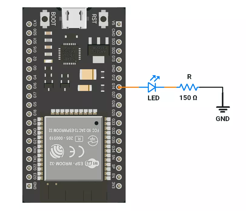
ESP32 Circuit Connection
- Interface LED to GPIO pin 14 with a 150 Ω resistor.
ESP32 Firmware Implementation
Code
#define LED_PIN 14

void setup() {
  Serial.begin(115200);

  // Attach LED_PIN to PWM with 1 kHz frequency, 12-bit resolution
  if (!ledcAttach(LED_PIN, 1000, 12)) {
    Serial.println("Failed to attach LEDC to pin");
  }

  // Start with 0 duty cycle (LED off)
  ledcWrite(LED_PIN, 0);
}

void loop() {
  /*
   Fade in: Gradually increase brightness from 0 to 4095 over 2 seconds
   - There are 4096 brightness levels (0 to 4095)
   - Total time for fade-in: 2000 milliseconds (2 seconds)
   - Delay per step: 2000 ms / 4096 = ~488  microseconds
  */
  for (int duty = 0; duty < 4096; duty++) {
    ledcWrite(LED_PIN, duty);  // Set duty cycle on the pin
    delayMicroseconds(488);    // Pause for 488 microseconds per step
  }

  /*
   Fade out: Gradually decrease brightness from 4095 to 0 over 1 second
   - There are 4096 brightness levels (4095 to 0)
   - Total time for fade-out: 1000 milliseconds (1 second)
   - Delay per step: 1000 ms / 4096 = ~244 microseconds
  */
  for (int duty = 4095; duty >= 0; duty--) {
    ledcWrite(LED_PIN, duty);  // Set duty cycle on the pin
    delayMicroseconds(244);    // Pause for 244 microseconds per step
  }
}
We are using the Arduino UNO development board and programming it using the Arduino IDE.
- Before uploading, make sure to select “Arduino UNO” as the board to ensure correct settings and compatibility.
The LED is connected to an Arduino UNO, and its brightness is controlled using PWM.
On Arduino UNO, the PWM signal is generated using the analogWrite() function, which outputs an 8-bit PWM signal (0–255 duty cycle).
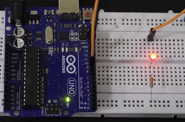
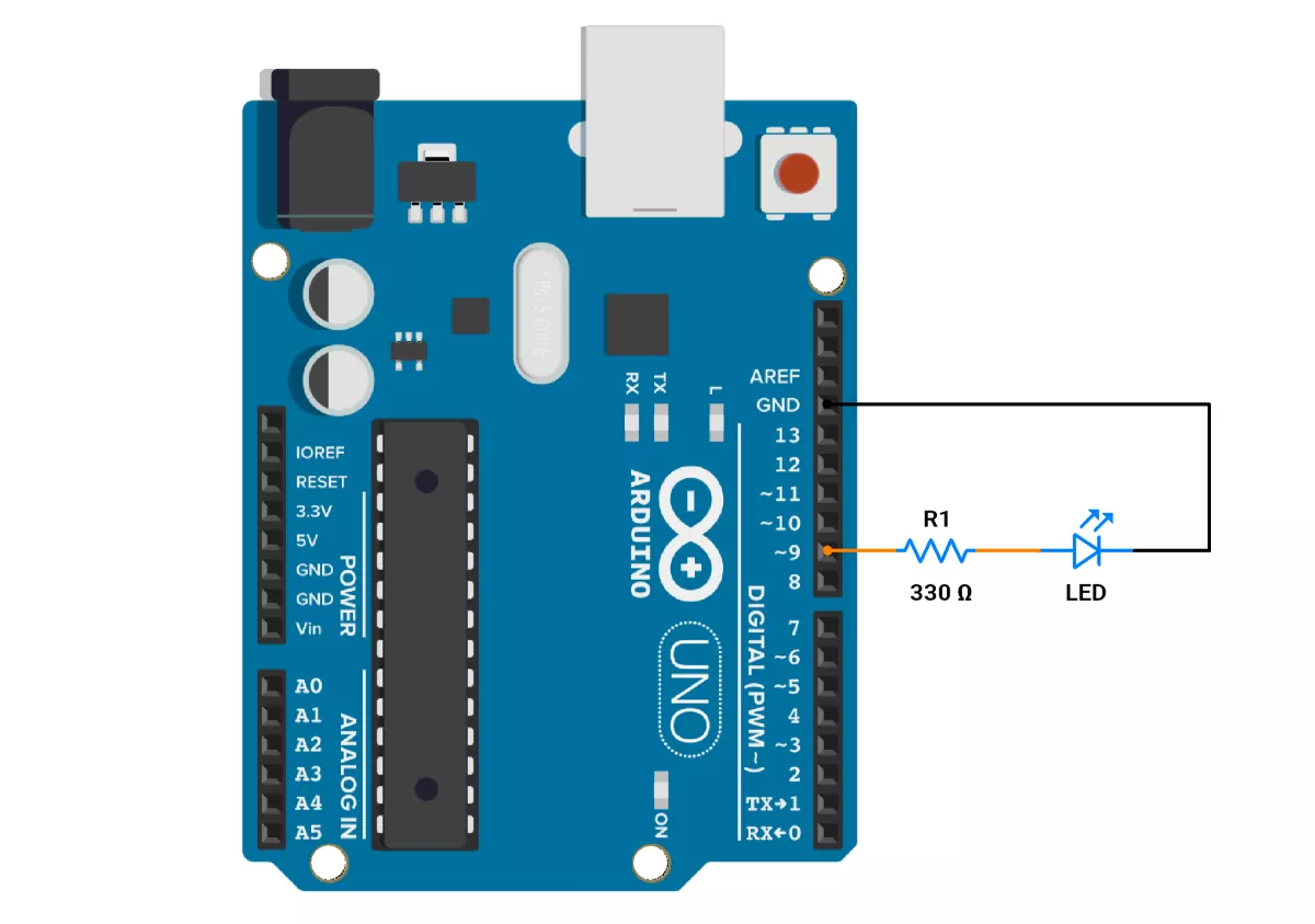
Arduino UNO Circuit connection
- Interface LED to GPIO pin 9 with a 330Ω resistor.
Circuit Diagram
Arduino UNO Firmware Implementation
Code
// LED is connected to Pin no. 9 (must be a PWM-capable pin for analogWrite)
void setup() {
  pinMode(9, OUTPUT);  // Set pin 9 as an output to control the LED
}

void loop() {
  /*
   Fade in: Gradually increase brightness from 0 to 255 over 2 seconds
   - There are 256 brightness levels (0 to 255)
   - Total time for fade-in: 2000 milliseconds (2 seconds)
   - Delay per step: 2000 ms / 256 = ~7.812 ms or 7812 microseconds
  */
  for (int brightness = 0; brightness <= 255; brightness++) {
    analogWrite(9, brightness);  // Set the LED brightness (PWM value)
    delayMicroseconds(7812);     // Pause for 7812 microseconds per step
  }

  /*
   Fade out: Gradually decrease brightness from 255 to 0 over 1 second
   - There are 256 brightness levels (255 to 0)
   - Total time for fade-out: 1000 milliseconds (1 second)
   - Delay per step: 1000 ms / 256 = ~3.906 ms or 3906 microseconds
  */
  for (int brightness = 255; brightness >= 0; brightness--) {
    analogWrite(9, brightness);  // Set the LED brightness (PWM value)
    delayMicroseconds(3906);     // Pause for 3906 microseconds per step
  }
}
Output