16. LED Brightness Control Using PWM
Back To All Submissions
Previous Submission
Next Submission
Solving Approach:
How do you plan to solve it?
Code
/*Paste your code here*/
nt main(void) {
  /* Reset of all peripherals, Initializes the Flash interface and the Systick. */
  HAL_Init();

  /* Configure the system clock */
  SystemClock_Config();

  /* Initialize all configured peripherals */
  MX_GPIO_Init();
  MX_USART2_UART_Init();   //optional
  MX_TIM4_Init();
  MX_TIM1_Init();

  HAL_TIM_PWM_Start(&htim1, TIM_CHANNEL_1);  // Start PWM on TIM1 CH1

  while (1) {

    /* PHASE 1: Configure TIM4 with prescaler=1 and generate upward PWM ramp
         * - Stops TIM4 to modify configuration
         * - Sets slower clock prescaler for TIM4 (longer delay between steps)
         * - Ramp up PWM duty cycle from 0% to 100% (0 to 10000)
         * - Uses TIM4 overflow as delay between PWM steps
         */
    // Stop TIM4 to reconfigure
    HAL_TIM_Base_Stop(&htim4);

    // Set slower prescaler (1) for longer delay
    htim4.Init.Prescaler = 1;

    // Reinitialize TIM4 with new prescaler
    HAL_TIM_Base_Init(&htim4);

    // Restart TIM4 in polling mode
    HAL_TIM_Base_Start(&htim4);

    // Ramp up PWM duty cycle (0 → 10000)
    for (int i = 0; i < 10000; i++) {
      // Update PWM duty cycle
      __HAL_TIM_SET_COMPARE(&htim1, TIM_CHANNEL_1, i);

      // Wait for TIM4 overflow (delay)
      while (__HAL_TIM_GET_FLAG(&htim4, TIM_FLAG_UPDATE) == RESET)
        ;

      // Clear overflow flag for next cycle
      __HAL_TIM_CLEAR_FLAG(&htim4, TIM_FLAG_UPDATE);
    }

    /* PHASE 2: Configure TIM4 with prescaler=0 and generate downward PWM ramp
         * - Stops TIM4 to modify configuration
         * - Sets faster clock prescaler for TIM4 (shorter delay between steps)
         * - Ramp down PWM duty cycle from 100% to 0% (10000 to 0)
         * - Uses TIM4 overflow as delay between PWM steps
         */
    // Stop TIM4 to reconfigure
    HAL_TIM_Base_Stop(&htim4);

    // Set fastest prescaler (0) for minimal delay
    htim4.Init.Prescaler = 0;

    // Reinitialize TIM4 with new prescaler
    HAL_TIM_Base_Init(&htim4);

    // Restart TIM4 in polling mode
    HAL_TIM_Base_Start(&htim4);

    // Ramp down PWM duty cycle (10000 → 0)
    for (int i = 10000; i >= 0; i--) {
      // Decrease PWM duty cycle
      __HAL_TIM_SET_COMPARE(&htim1, TIM_CHANNEL_1, i);

      // Wait for TIM4 overflow (shorter delay than before)
      while (__HAL_TIM_GET_FLAG(&htim4, TIM_FLAG_UPDATE) == RESET)
        ;

      // Clear overflow flag for next step
      __HAL_TIM_CLEAR_FLAG(&htim4, TIM_FLAG_UPDATE);
    }
  }
}
Output
Video
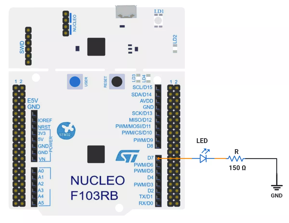
Photo of Output
Add a photo of your hardware showing the output.
Was this helpful?
Upvote
Downvote