60. LED Patterns Switching
We need to toggle between two LED blinking patterns using a push-button, while the main loop is busy with other tasks.
To ensure instant response and non-blocking operation, we use interrupts.
Implementation Concept
- External Interrupt:
- Triggered on a button press to change the LED pattern immediately.
- Detects input changes without polling in the main loop.
- Timer Interrupt:
- Generates periodic events to toggle LEDs for blinking or debouncing the switch.
- Keeps LED timing independent of main loop load.
Hardware Setup
- Connect two LEDs with appropriate current-limiting resistors to limit the current to 10 mA.
- One push-button configured to provide clean HIGH/LOW levels (with pull-up or pull-down).
So, by selecting a proper resistor, LED, and push-button switch correctly, we can implement the task.
Below are the solutions to the given task using different microcontrollers
- STM32
- ESP32
- Arduino UNO
We’re using an STM32 NUCLEO-F103RB board, which runs at a 3.3V logic level.
Key Peripherals Used
- GPIO: To connect a push-button switch and LEDs.
Hardware Connection
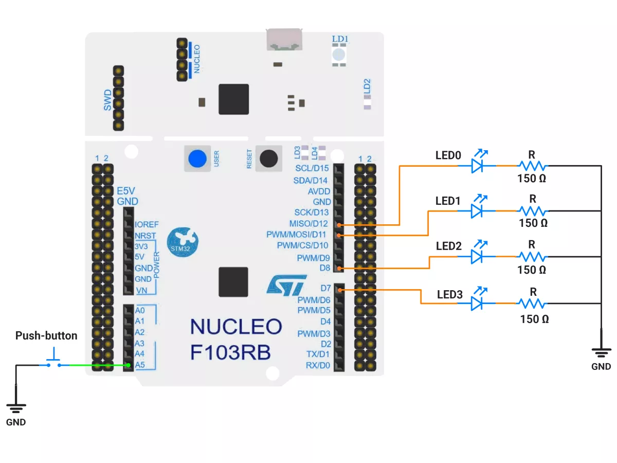
- Switch: Connect one terminal of the push-button switch to GPIO pin PC0(A5) and the other terminal to GND. Enable the internal pull-up resistor for PC0 in the software.
- LEDs: Connect anodes of LED0, LED1, LED2, and LED3, to GPIO pins PA6(D12), PA7(D11), PA9(D8), and PA8(D7) respectively. Connect their cathodes to ground through appropriate resistors.
Circuit Diagram
Firmware Implementation
Project Setup in STM32CubeIDE
- Create a Project
- Open STM32CubeIDE and start a new project, select the NUCLEO-F103RB board.
- Basic Configuration (via CubeMX inside CubeIDE)
- Clock: Use default HSI + PLL (SystemClock_Config provided by Cube, typical SYSCLK ≈ 64 MHz).
- GPIO Configuration:
- Switch: Set GPIO PC0 as GPIO_EXTI on a falling edge in the Pinout view (via STM32CubeMX, built into CubeIDE).
- LEDs: Set GPIO PA6, PA7, PA9, and PA8 as GPIO Output Push-Pull in the Pinout view (via STM32CubeMX, built into CubeIDE).
- NVIC: Enable EXTI line 0 interrupt.
- TIM2 – 10 ms periodic ticker
- Mode: Internal Clock
- Prescaler = 64000 − 1
- Counter Mode = Up
- Period (ARR) = 10 − 1
- Auto-reload preload = Disable
- Enable Update Interrupt (TIM2 global interrupt in NVIC)
- Why these values?
Timer clock = 64 MHz → tick = (PSC+1)/f = 64000/64 MHz = 1 ms.
Period 10 → 10 ms interrupt.
- TIM3 – 20 ms debounce one-shot
- Mode: Internal Clock
- Prescaler = 64000 − 1
- Counter Mode = Up
- Period (ARR) = 20 − 1
- Auto-reload preload = Disable
- Enable Update Interrupt (TIM3 global interrupt in NVIC)
- We’ll start/stop TIM3 in code to behave like a one-shot (start on button press, stop in the ISR)
- Code Generation
- CubeMX will automatically generate all the startup code, including:
HAL_Init()→ Initializes the HAL library.SystemClock_Config()→ Configures system clock.MX_GPIO_Init()→ Configures GPIO pins.MX_TIM2_Init()→ Configures Timer2MX_TIM3_Init()→ Configures Timer3
- This code sets up the hardware and prepares the project for firmware development, so we only need to add our application logic in the user code sections
- CubeMX will automatically generate all the startup code, including:
Firmware Design
Behavior Summary
- Two pattern sets, each has 2 frames of 4 LED bits:
- Set 0: [1111] then [0000]
- Set 1: [1010] then [0101]
- TIM2: fires every 10 ms; after 100 ticks (1 s), it toggles the frame to animate.
- Button on PC0: when push button pressed (falling edge), start TIM3 (20 ms). If the button is still held low when TIM3 elapses, it’s a valid press → toggle pattern set and request an immediate update on the next TIM2 tick.
- Debounce lockout: a flag prevents re-triggering the debounce until the one-shot ends.
Timing Math Check
- TIM2: 10 ms periodic → isr_call_count counts to 100 → 1 s per frame change.
- TIM3: 20 ms one-shot → common mechanical debounce.
Code Snippets from main.c
GPIO Initialization
// In MX_GPIO_Init()

  /*Configure GPIO pin Output Level */
  HAL_GPIO_WritePin(GPIOA, GPIO_PIN_6|GPIO_PIN_7|GPIO_PIN_8|GPIO_PIN_9, GPIO_PIN_RESET);

  /*Configure GPIO pin : PC0 */
  GPIO_InitStruct.Pin = GPIO_PIN_0;
  GPIO_InitStruct.Mode = GPIO_MODE_IT_FALLING;
  GPIO_InitStruct.Pull = GPIO_PULLUP;
  HAL_GPIO_Init(GPIOC, &GPIO_InitStruct);

  /*Configure GPIO pins : PA6 PA7 PA8 PA9 */
  GPIO_InitStruct.Pin = GPIO_PIN_6|GPIO_PIN_7|GPIO_PIN_8|GPIO_PIN_9;
  GPIO_InitStruct.Mode = GPIO_MODE_OUTPUT_PP;
  GPIO_InitStruct.Pull = GPIO_NOPULL;
  GPIO_InitStruct.Speed = GPIO_SPEED_FREQ_LOW;
  HAL_GPIO_Init(GPIOA, &GPIO_InitStruct);

  /* EXTI interrupt init*/
  HAL_NVIC_SetPriority(EXTI0_IRQn, 0, 0);
  HAL_NVIC_EnableIRQ(EXTI0_IRQn);
This configuration initializes the button on PC0 as an external interrupt input with a pull-up resistor, ensuring the line is normally HIGH and triggers an interrupt when pressed (falling edge).
The four LEDs (PA6, PA7, PA8, PA9) are configured as push-pull digital outputs, allowing each pin to drive its LED either HIGH (on) or LOW (off) with strong current capability.
Macros for Ports and Pins
#define SWITCH0_PORT GPIOC
#define SWITCH0_PIN  GPIO_PIN_0

#define LED0_PORT GPIOA
#define LED0_PIN  GPIO_PIN_6

#define LED1_PORT GPIOA
#define LED1_PIN  GPIO_PIN_7

#define LED2_PORT GPIOA
#define LED2_PIN  GPIO_PIN_9

#define LED3_PORT GPIOA
#define LED3_PIN  GPIO_PIN_8
These macros provide human-readable names for the switch and LED pins, improving code clarity and maintainability.
Changing pin assignments in the future only requires modifying these definitions instead of editing multiple code sections.
Private Variables
// 2 pattern sets, each containing 2 frames of 4 LED states
const uint8_t patterns[2][2][4] = {
  { {1,1,1,1}, {0,0,0,0} },  // Pattern Set 0: All ON → All OFF
  { {1,0,1,0}, {0,1,0,1} }   // Pattern Set 1: Alternating pattern
};

// Global control flags and counters
volatile uint8_t pattern = 0;         // Current pattern set (0 or 1)
volatile uint8_t patternIndex = 0;    // Current frame index (0 or 1)
volatile uint8_t buttonPressed = 0;   // Flag for a validated button press
volatile uint8_t isr_call_count = 0;  // Counts 10 ms ticks → 1 second cycle
volatile uint8_t debounceArmed = 1;   // Prevents multiple presses during debounce
These variables manage LED patterns and button logic.
patterns[][][]defines the LED states for each frame.- pattern toggles between pattern sets when the button is pressed.
patternIndexswitches between frames within a pattern every second.debounceArmedensures only one press is accepted during each 20 ms debounce interval.
Key Private Functions
a) LED Frame Writer
// Updates the LED outputs according to the selected pattern frame
static inline void LEDs_WriteFrame(uint8_t p, uint8_t idx)
{
  HAL_GPIO_WritePin(LED0_PORT, LED0_PIN, patterns[p][idx][0] ? GPIO_PIN_SET : GPIO_PIN_RESET);
  HAL_GPIO_WritePin(LED1_PORT, LED1_PIN, patterns[p][idx][1] ? GPIO_PIN_SET : GPIO_PIN_RESET);
  HAL_GPIO_WritePin(LED2_PORT, LED2_PIN, patterns[p][idx][2] ? GPIO_PIN_SET : GPIO_PIN_RESET);
  HAL_GPIO_WritePin(LED3_PORT, LED3_PIN, patterns[p][idx][3] ? GPIO_PIN_SET : GPIO_PIN_RESET);
}
This function writes a frame of LED states to the GPIO pins.
It ensures all LEDs update simultaneously according to the selected pattern set and frame index.
b) External Interrupt Callback
// Triggered when PC0 detects a falling edge (button press)
void HAL_GPIO_EXTI_Callback(uint16_t GPIO_Pin)
{
  if (GPIO_Pin == SWITCH0_PIN)
  {
    if (debounceArmed)
    {
      debounceArmed = 0;
      __HAL_TIM_SET_COUNTER(&htim3, 0);
      HAL_TIM_Base_Start_IT(&htim3);   // Start 20 ms debounce one-shot timer
    }
  }
}
When the button is pressed, this callback arms Timer 3 to begin a 20-ms one-shot debounce window. During this time, subsequent interrupts are ignored, preventing false triggers from mechanical bounce.
c) Timer Interrupt Handler
// Called when a timer period elapses
void HAL_TIM_PeriodElapsedCallback(TIM_HandleTypeDef *htim)
{
  // TIM2: 10 ms periodic timer (for pattern updates)
  if (htim->Instance == TIM2)
  {
    isr_call_count++;
    if (isr_call_count >= 100 || buttonPressed) // 100×10ms = 1s
    {
      LEDs_WriteFrame(pattern, patternIndex);
      patternIndex ^= 1;         // Toggle between the two frames
      isr_call_count = 0;
      buttonPressed = 0;
    }
  }

  // TIM3: 20 ms debounce timer
  if (htim->Instance == TIM3)
  {
    HAL_TIM_Base_Stop_IT(&htim3);   // Stop the one-shot timer
    if (HAL_GPIO_ReadPin(SWITCH0_PORT, SWITCH0_PIN) == GPIO_PIN_RESET)
    {
      pattern ^= 1;                 // Switch to the other pattern set
      buttonPressed = 1;            // Force immediate LED update
    }
    debounceArmed = 1;              // Re-arm for the next button press
  }
}
TIM2 (10 ms periodic):
Used for frame timing. Every 100 interrupts (≈1 s), the active LED frame toggles.
If a button press occurs, an immediate frame update happens without waiting for the 1-second mark.
TIM3 (20 ms one-shot):
Used for debouncing. After 20 ms, it checks if the button is still pressed (active-low).
If true, it confirms a valid press, toggles the pattern, and re-enables button detection.
Main Firmware Logic
int main(void)
{
  HAL_Init();                 // Initialize HAL and SysTick
  SystemClock_Config();       // Configure system clock (HSI+PLL 64 MHz)
  MX_GPIO_Init();             // Configure LEDs and switch pins
  MX_USART2_UART_Init();      // Optional debugging UART
  MX_TIM2_Init();             // 10 ms periodic timer
  MX_TIM3_Init();             // 20 ms debounce one-shot timer

  // Start periodic timer
  HAL_TIM_Base_Start_IT(&htim2);

  // Initialize LEDs with the first frame
  LEDs_WriteFrame(pattern, patternIndex);

  while (1)
  {
    // Main loop intentionally empty: fully interrupt-driven
  }
}
Step-by-step:
- The system and peripherals are initialized.
- Timer 2 starts generating periodic interrupts every 10 ms.
- LEDs are set to the initial pattern frame.
- Inside the infinite loop, no active code runs — all logic is interrupt-driven:
- TIM2 ISR handles frame timing.
- TIM3 ISR validates button presses.
- EXTI ISR starts debounce one-shot timers.
This design provides a clean, responsive, and low-CPU solution with precise timing.
Behavior Summary
- Every 1 second, LED frame alternates automatically within the selected pattern.
- When the button is pressed, pattern set toggles (between [1111]↔[0000] and [1010]↔[0101]).
- Debounce logic prevents multiple toggles from a single physical press.
- The firmware is fully event-driven — no blocking delays or polling loops.
Download Project
The complete STM32CubeIDE project (including .ioc configuration, main.c, and HAL drivers) is available here:
📥 Download Project
We are using the ESP32 DevKitC v4 development board and programming it using the Arduino IDE.
- Before uploading, make sure to select “ESP32 Dev Module” as the board to ensure correct settings and compatibility.
Hardware Connection
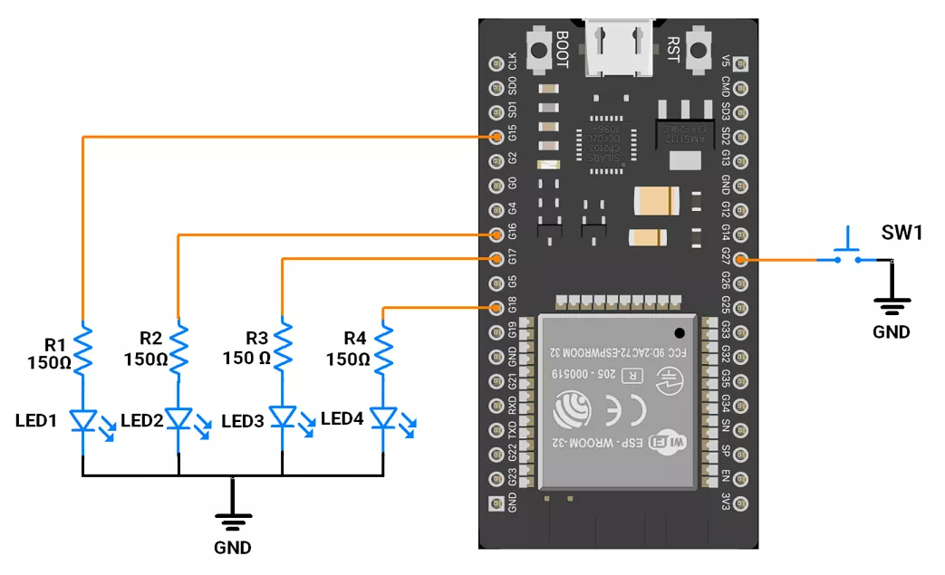
- Interface 4 LEDs to GPIO pins 15, 16, 17, and 18 with a 150-ohm current-limiting resistor.
- Push‑Button Interfacing (Internal Pull‑up Configuration)
- One terminal to GPIO 13.
- Other terminal to GND.
- In software, configure it as INPUT_PULLUP so the pin reads HIGH when idle and LOW when pressed.
Note: Avoid using GPIOs 34–39 for push-buttons while using ESP32 because they do not support pull-up/down resistors internally.
Circuit Connection
Code
#include <Arduino.h>
#include "driver/gpio.h"
#include "soc/gpio_struct.h"  // for GPIO.out_w1ts / GPIO.out_w1tc

#define BUTTON_PIN 13                                  // push-button (active LOW)
static const uint8_t ledPins[4] = { 15, 16, 17, 18 };  // LEDs (all <32 → same register bank)
uint8_t timerCount = 0;

static const uint8_t patterns[2][2][4] = {
  { { 1, 1, 1, 1 }, { 0, 0, 0, 0 } },  // pattern set 0
  { { 1, 0, 1, 0 }, { 0, 1, 0, 1 } }   // pattern set 1
};


volatile bool pattern = 0;       // which pattern set (toggled on button)
volatile bool patternIndex = 0;  // flips every update
volatile bool buttonPressed = false;
volatile bool timerFlag = true;  // to arm debounce


hw_timer_t* debounceTimer = nullptr;  // 20 ms one-shot
hw_timer_t* patternTimer = nullptr;   // 1 s periodic


void IRAM_ATTR isButtonPress();           // GPIO ISR
void ARDUINO_ISR_ATTR onDebounceTimer();  // 20 ms one-shot
void ARDUINO_ISR_ATTR onPatternTick();    // 1 s periodic


// Build a 4-bit LED pattern from tables
static inline uint8_t makeLedBits(bool pat, bool idx) {
  uint8_t b = 0;
  b |= (patterns[pat][idx][0] ? 1 : 0) << 0;
  b |= (patterns[pat][idx][1] ? 1 : 0) << 1;
  b |= (patterns[pat][idx][2] ? 1 : 0) << 2;
  b |= (patterns[pat][idx][3] ? 1 : 0) << 3;
  return b;
}

// Write LED bits directly (atomic, ISR-safe)
static inline void IRAM_ATTR writeLedsMask(uint8_t bits) {
  uint32_t setMask = 0, clrMask = 0;
  for (int i = 0; i < 4; ++i) {
    uint32_t pinMask = (1u << ledPins[i]);
    if (bits & (1u << i)) setMask |= pinMask;
    else clrMask |= pinMask;
  }
  if (setMask) GPIO.out_w1ts = setMask;
  if (clrMask) GPIO.out_w1tc = clrMask;
}


void setup() {
  Serial.begin(115200);
  // LED setup
  for (uint8_t i = 0; i < 4; i++) {
    pinMode(ledPins[i], OUTPUT);
    digitalWrite(ledPins[i], LOW);
  }

  // Button setup
  pinMode(BUTTON_PIN, INPUT_PULLUP);
  attachInterrupt(digitalPinToInterrupt(BUTTON_PIN), isButtonPress, FALLING);

  // 20 ms debounce timer: one-shot
  debounceTimer = timerBegin(1'000'000);  // 1 MHz base
  timerAttachInterrupt(debounceTimer, &onDebounceTimer);
  timerAlarm(debounceTimer, 20'000, false, 0);  // 20 ms one-shot
  timerStop(debounceTimer);
  timerWrite(debounceTimer, 0);

  // Pattern timer of 10msec
  patternTimer = timerBegin(1'000'000);  // 1 MHz base
  timerAttachInterrupt(patternTimer, &onPatternTick);
  timerAlarm(patternTimer, 10000 /*us*/, true, 0);  // 10msec auto-reload

  // Show initial pattern
  writeLedsMask(makeLedBits(pattern, patternIndex));
}


void loop() {
  // Controller is busy doing some important task
  Serial.println(timerCount);
}


// Button ISR (falling edge): start debounce timer if idle
void IRAM_ATTR isButtonPress() {
  if (timerFlag) {
    timerFlag = false;
    timerWrite(debounceTimer, 0);
    timerStart(debounceTimer);
  }
}

// Debounce timer ISR: confirm press and toggle pattern
void ARDUINO_ISR_ATTR onDebounceTimer() {
  timerFlag = true;
  if (gpio_get_level((gpio_num_t)BUTTON_PIN) == 0) {
    pattern = !pattern;
    buttonPressed = true;
  }
  timerStop(debounceTimer);
}

// toggle LEDs
void ARDUINO_ISR_ATTR onPatternTick() {
  if (timerCount == 100 || buttonPressed) {
    uint8_t bits = makeLedBits(pattern, patternIndex);
    writeLedsMask(bits);
    patternIndex = !patternIndex;
    buttonPressed = false;
    timerCount = 0;
  } else
    timerCount++;
}
Code Explanation
Interrupts
1.Button Press ISR (isButtonPress())
- Triggered on the falling edge of the push-button (active LOW).
- If the debounce timer is idle (
timerFlag = true), it starts the 20-ms one-shot timer for debouncing. - This ensures the button press is processed only once, preventing multiple triggers from mechanical bounce.
2. Debounce Timer ISR (onDebounceTimer())
- Called after 20 ms to confirm a valid button press.
- If the button pin is still LOW (pressed), it marks the button press as valid by setting:
pattern = !pattern;→ toggles LED pattern set.buttonPressed = true;
- Stops the debounce timer and resets the flag (
timerFlag = true) so it can detect the next press.
3. Pattern Timer ISR (onPatternTick())
- Runs every 10 msec(periodic timer).
- Responsible for updating LED states:
- If
buttonPressedis true (pattern change detected) or after every 1 sec, it updates LEDs using the current pattern and pattern index. patternIndextoggles (0 ↔ 1) each second to animate LEDs alternately.- The LED pattern is written atomically using low-level GPIO registers (
GPIO.out_w1ts / GPIO.out_w1tc), ensuring ISR-safe updates.
- If
Timer Configuration
1. Debounce Timer (20 ms one-shot)
- Created with
timerBegin(1000000)at 1 MHz base frequency. timerAlarm(debounceTimer, 20’000, false, 0);
→ Interrupt every 20 000 µs = 20 ms (non-repeating).- Used for debouncing the button.
2 . Pattern Timer (10 ms periodic)
- Also created with
timerBegin(1000000);at 1 MHz. timerAlarm(patternTimer, 10’000, true, 0);
→ Interrupt every 1 000 0 µs = 10 ms (auto-reload).- Used to toggle the LED state.
We are using the Arduino UNO development board and programming it using the Arduino IDE.
- Before uploading, make sure to select “Arduino UNO” as the board to ensure correct settings and compatibility.
We will use external and timer interrupts for button detection.
- Interrupts on Arduino Uno:
- External Interrupts:
- INT0 (Pin 2, higher priority).
- INT1 (Pin 3).
- Timer Interrupts:
- Timer0, Timer1, and Timer2 are available.
- External Interrupts:
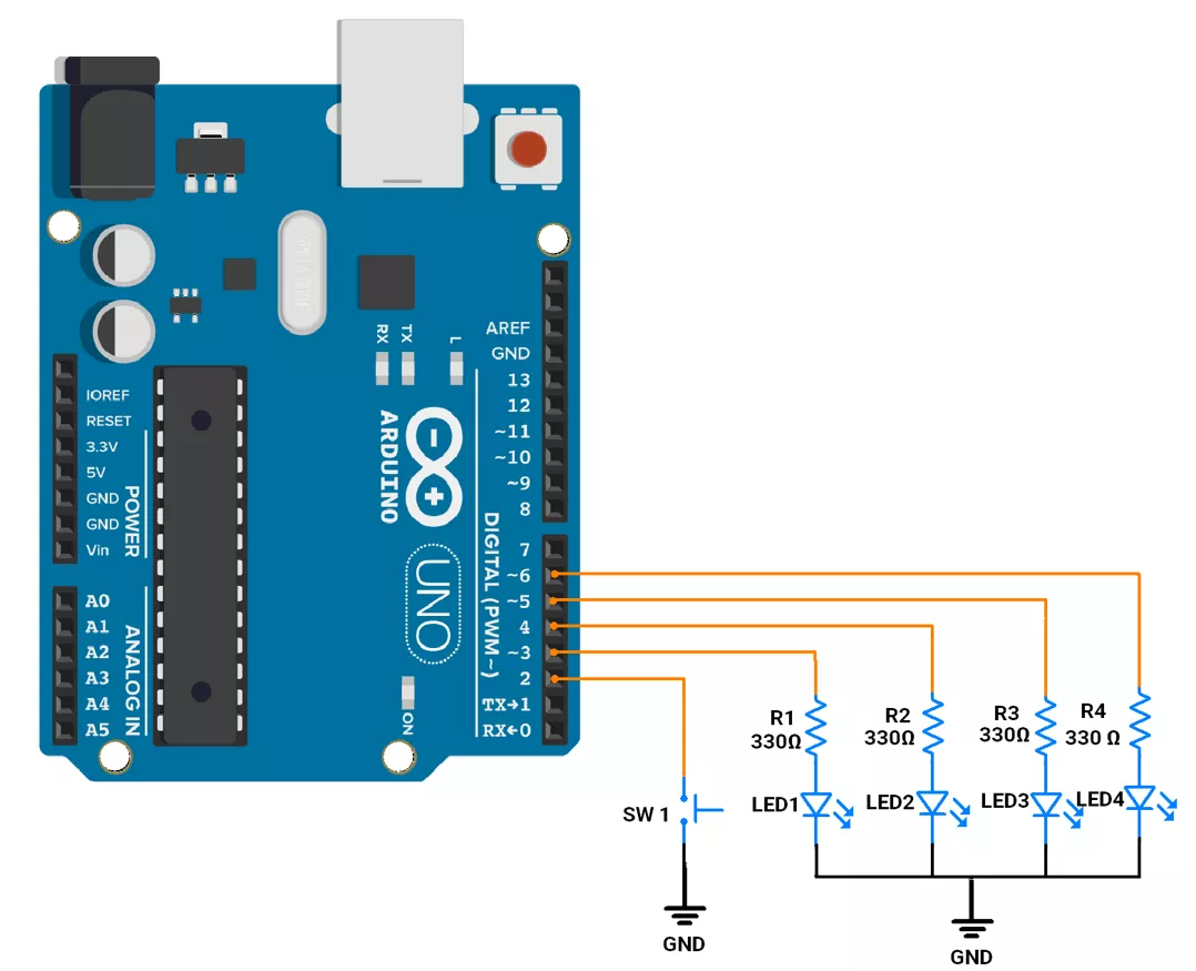
Hardware connection
- Push button → Pin 2 (internal pull-up)
- 4 LEDs → Arduino UNO (GPIO pins 3,4,5,6)
- Use a 330 Ohm resistor for each LED to limit current to 10mA.
Circuit connection
Firmware
We will implement the following approach for the task:
- External Interrupt (INT0): Used to detect button presses for switching LED patterns.
- Timer 1: Used to handle the debouncing delay of the button.
- Timer 2: Used to generate a 1-second delay for transitioning between LED patterns.
Code
#define BUTTON_PIN 2  // Push button connected to pin 2 (interrupt pin)

// Pattern Array (2 sets of 2 patterns)
const int patterns[2][2][4] = {
  { { 1, 1, 1, 1 },  // pattern 1
    { 0, 0, 0, 0 } },
  { { 1, 0, 1, 0 },  // pattern 2
    { 0, 1, 0, 1 } }
};

// LED Pin Array
const uint8_t ledPins[] = { 3, 4, 5, 6 };

volatile bool pattern = 0;
volatile bool patternIndex = 0;
volatile bool buttonPressed = false;
volatile bool timerFlag = true;
volatile uint8_t isr_call_count = 0;

void setup() {
  // Set all LED pins as OUTPUT
  for (uint8_t i = 0; i < 4; i++) {
    pinMode(ledPins[i], OUTPUT);
  }

  pinMode(BUTTON_PIN, INPUT_PULLUP);

  // Attach interrupt to button pin, trigger on FALLING edge (button press)
  attachInterrupt(digitalPinToInterrupt(BUTTON_PIN), isButtonPress, FALLING);

  /* Configuring Timer 1 for 20 msec delay */
  TCCR1A = 0;                                         // Normal operation
  TCCR1B = (1 << WGM12) | (1 << CS12) | (1 << CS10);  // CTC mode, prescaler = 1024
  OCR1A = 312;                                        // Set compare match value (for 20ms interrupt with 1024 prescaler)

  /* Configuring Timer 2 for 10 msec delay */
  TCCR2A = 0;                                         // Normal operation
  TCCR2B = (1 << WGM22) | (1 << CS22) | (1 << CS21);  // CTC mode, prescaler = 1024
  OCR2A = 156;                                        // Set compare match value (for 10ms interrupt with 1024 prescaler)
  TIMSK2 |= (1 << OCIE2A);                            // enable Timer2 Compare A interrupt

  // enable global interrupt
  sei();
}

void loop() {
  while (true) {
    // microcontroller is busy in doing critcal task countinously.
  }
}

// Interrupt Service Routine (ISR) to handle button press
void isButtonPress() {
  if (timerFlag == true) {

    // set prescaler to 1024
    TCCR1B |= (1 << CS12);
    TCCR1B |= (1 << CS10);

    // Enable Timer1 Compare  interrupt
    TIMSK1 = (1 << OCIE1A);
    timerFlag = false;
  }
  TCNT1 = 0;  // Reset timer count to 0.
}

// Timer1 interrupt service routine for 20 msec debounce delay check
ISR(TIMER1_COMPA_vect) {

  timerFlag = true;
  if (digitalRead(BUTTON_PIN) == LOW) {
    pattern = !pattern;
    buttonPressed = true;
  }

  // Disable Timer1 interrupt after 20ms
  TIMSK1 &= ~(1 << OCIE1A);  // Disable Timer1 Compare A interrupt

  // Stop Timer1 by clearing prescaler bits
  TCCR1B &= ~(1 << CS12);
  TCCR1B &= ~(1 << CS10);
  TCCR1B &= ~(1 << CS20);
}

//Timer2 to ISR is called after every 10ms delay
ISR(TIMER2_COMPA_vect) {
  isr_call_count++;

  // update count after every 1 sec or if button press ocurre.
  if (isr_call_count == 100 || buttonPressed) {

    digitalWrite(ledPins[0], patterns[pattern][patternIndex][0]);
    digitalWrite(ledPins[1], patterns[pattern][patternIndex][1]);
    digitalWrite(ledPins[2], patterns[pattern][patternIndex][2]);
    digitalWrite(ledPins[3], patterns[pattern][patternIndex][3]);

    patternIndex = !patternIndex;
    isr_call_count = 0;
    buttonPressed = false;
  }
}
Code Explanation
Interrupts
1. Button Press ISR (isButtonPress())
- This ISR is triggered on the falling edge of the button press.
- It starts Timer1 to handle debouncing by
- Setting the prescaler for Timer1 to 1024.
- Enabling the Timer1 Compare Match interrupt (TIMSK1) for 20ms.
2. Timer1 Compare Match ISR (TIMER1_COMPA_vect())
- Triggered after 20 ms when button press for debounce handling:
- If the button is still pressed (
digitalRead(BUTTON_PIN) == LOW), it marks the button press as valid (buttonPressed = true) and changes the pattern by doingpattern = !pattern;, considering the button is pressed for a straight 20 ms. - Timer1 is then disabled.
- If the button is still pressed (
3. Timer2 Compare Match ISR (TIMER2_COMPA_vect())
- Called every 10ms:
- Periodic LED Updates:
- Every 100 interrupts (1 second) or if
buttonPressed == truethen LED pattern is updated based onpatternIndexandpattern. patternIndexalternates between 0 and 1.
- Every 100 interrupts (1 second) or if
- Periodic LED Updates:
Timer1 Configuration
- Timer1 is configured in CTC (Clear Timer on Compare Match) mode.
- The prescaler is set to 1024, and OCR1A is set to 312 for a 20ms debounce interval:
- Interrupt Time = (OCR1A + 1 * Prescaler ) / 16000000
= 20 msec.
Timer2 Configuration
- Timer2 is also set to CTC mode with a prescaler of 1024.
- OCR2A is set to 156 for a 10ms interrupt interval:
- Interrupt Time =(OCR2A + 1 * Prescaler ) / 16000000
= 10 msec
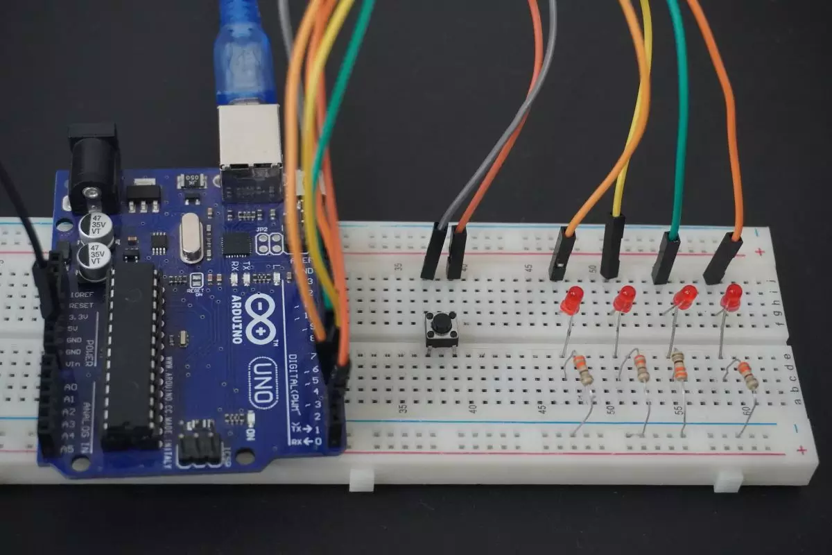
Output
Hardware Setup