60. LED Patterns Switching
Solving Approach
How do you plan to solve it?
Project Setup in STM32CubeIDE
Create a Project
Open STM32CubeIDE and start a new project, select the NUCLEO-F103RB board.
Basic Configuration (via CubeMX inside CubeIDE)
Clock: Use default HSI + PLL (SystemClock_Config provided by Cube, typical SYSCLK ≈ 64 MHz).
GPIO Configuration:
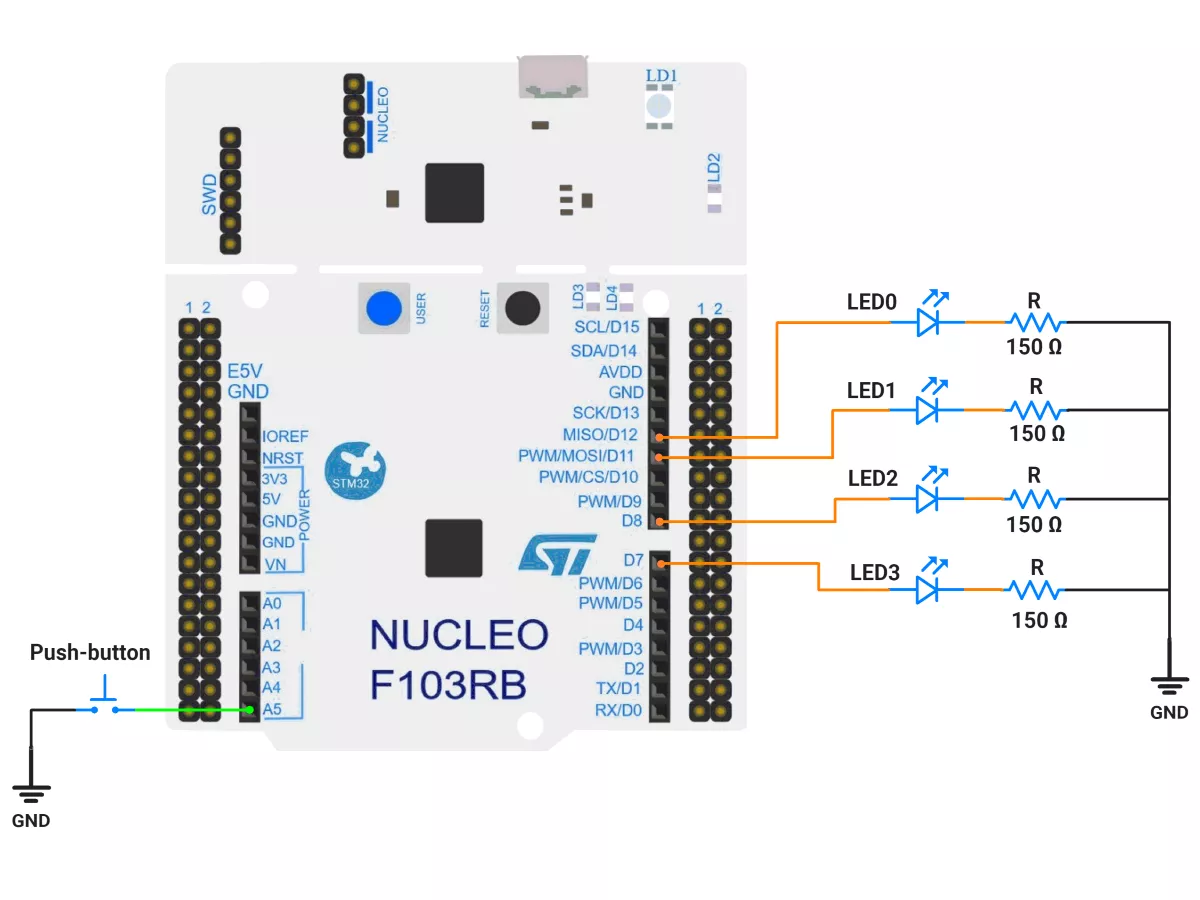
Switch: Set GPIO PC0 as GPIO_EXTI on a falling edge in the Pinout view (via STM32CubeMX, built into CubeIDE).
LEDs: Set GPIO PA6, PA7, PA9, and PA8 as GPIO Output Push-Pull in the Pinout view (via STM32CubeMX, built into CubeIDE).
NVIC: Enable EXTI line 0 interrupt.
TIM2 – 10 ms periodic ticker
Mode: Internal Clock
Prescaler = 64000 − 1
Counter Mode = Up
Period (ARR) = 10 − 1
Auto-reload preload = Disable
Enable Update Interrupt (TIM2 global interrupt in NVIC)
Why these values?
Timer clock = 64 MHz → tick = (PSC+1)/f = 64000/64 MHz = 1 ms.
Period 10 → 10 ms interrupt.
TIM3 – 20 ms debounce one-shot
Mode: Internal Clock
Prescaler = 64000 − 1
Counter Mode = Up
Period (ARR) = 20 − 1
Auto-reload preload = Disable
Enable Update Interrupt (TIM3 global interrupt in NVIC)
We’ll start/stop TIM3 in code to behave like a one-shot (start on button press, stop in the ISR)
Code Generation
CubeMX will automatically generate all the startup code, including:
HAL_Init()→ Initializes the HAL library.SystemClock_Config()→ Configures system clock.MX_GPIO_Init()→ Configures GPIO pins.MX_TIM2_Init()→ Configures Timer2MX_TIM3_Init()→ Configures Timer3
This code sets up the hardware and prepares the project for firmware development, so we only need to add our application logic in the user code sections
Firmware Design
Behavior Summary
Two pattern sets, each has 2 frames of 4 LED bits:
Set 0: [1111] then [0000]
Set 1: [1010] then [0101]
TIM2: fires every 10 ms; after 100 ticks (1 s), it toggles the frame to animate.
Button on PC0: when push button pressed (falling edge), start TIM3 (20 ms). If the button is still held low when TIM3 elapses, it’s a valid press → toggle pattern set and request an immediate update on the next TIM2 tick.
Debounce lockout: a flag prevents re-triggering the debounce until the one-shot ends.
Timing Math Check
TIM2: 10 ms periodic → isr_call_count counts to 100 → 1 s per frame change.
TIM3: 20 ms one-shot → common mechanical debounce.
Code
/*Paste your code here*/
nt main(void)
{
  HAL_Init();                 // Initialize HAL and SysTick
  SystemClock_Config();       // Configure system clock (HSI+PLL 64 MHz)
  MX_GPIO_Init();             // Configure LEDs and switch pins
  MX_USART2_UART_Init();      // Optional debugging UART
  MX_TIM2_Init();             // 10 ms periodic timer
  MX_TIM3_Init();             // 20 ms debounce one-shot timer

  // Start periodic timer
  HAL_TIM_Base_Start_IT(&htim2);

  // Initialize LEDs with the first frame
  LEDs_WriteFrame(pattern, patternIndex);

  while (1)
  {
    // Main loop intentionally empty: fully interrupt-driven
  }
}
Output
Video
Photo of Output
Add a photo of your hardware showing the output.