42. LED toggle using SPI
In this task, we'll set up SPI communication between two microcontrollers, one acting as the master and the other as the slave. The goal is to toggle an LED connected to the slave microcontroller by pressing a push-button connected to the master.
Components Needed
- Master Microcontroller (e.g., Arduino, STM32, ESP32)
- Slave Microcontroller (same or compatible family)
- Push-button switch (for the master)
- LED (for the slave)
- Current-limiting resistor (for the LED, typically 220Ω–1kΩ)
- Breadboard & jumper wires
Hardware Setup
Push-Button (Master Side)
- Connect one terminal of the push-button to a GPIO pin on the master (configured as input).
- Use an internal or external pull-up or pull-down resistor to avoid floating signals.
- Optionally, add a debounce circuit (hardware RC filter) or implement software debouncing.
LED (Slave Side)
- Connect the LED to a GPIO pin on the slave (configured as output).
- Add a current-limiting resistor (e.g., 330Ω) in series with the LED and GND.
SPI Connections between master and slave
| Master Pin | Slave Pin |
|---|---|
| SCK(Clock) | SCK |
| MOSI(Master Out Slave In) | MOSI |
| MISO(Master In Slave Out) | MISO |
| SC/CS(Slave Select) | SS |
Note: If you only need one-way communication (Master → Slave), you can omit the MISO line.
What if Voltage Levels Are Different?
- SPI signals (SCK, MOSI, MISO, CS) are digital logic signals. If the two microcontrollers operate at different logic voltages (e.g., 5V Arduino as Master and 3.3V ESP32 as Slave), a direct connection can damage the lower-voltage device or cause unreliable communication.
- Example Scenario
- Arduino UNO (5V) → ESP32 (3.3V):
- Arduino's output HIGH = 5V, which exceeds ESP32’s max 3.3V input tolerance, risking permanent damage.
- Arduino UNO (5V) → ESP32 (3.3V):
- Solutions
- Level Shifter IC (Preferred)
- Use bidirectional level shifters for MOSI, MISO, and SCK lines.
- Voltage Divider (for MOSI & SCK going to 3.3V device)
- Example: Two resistors (e.g., 10kΩ & 20kΩ) to step down 5V → 3.3V.
- Use 3.3V Logic-Compatible Devices (Simplest)
- If possible, select both microcontrollers that operate at the same voltage level.
- Level Shifter IC (Preferred)
Important: The CS/SS line also needs level shifting if coming from a higher voltage device.
How It Works
- The master detects a button press (with debouncing).
- It sends a command byte (e.g., 0x01 = ON, 0x00 = OFF) over SPI.
- The slave receives the command and toggles the LED state (ON ↔ OFF).
- (Optional) The slave can send back a status byte for verification.
Expected Behavior
- Each press of the button on the master toggles the LED on the slave (ON → OFF → ON → ...).
Implementation (Pseudocode)
Master (pseudocode)
- Initialize:
- Configure the button GPIO as input with pull-up/pull-down.
- Initialize SPI as Master (set clock polarity/phase, speed, MSB/LSB as required).
- Loop:
- Read button state and detect edge (press event with debounce).
- On valid press, assert CS low.
- Transmit command byte (e.g., 0x01).
- Optionally read the response byte.
- Deselect CS high.
Slave (pseudocode)
- Initialize:
- Configure LED GPIO as output (start OFF).
- Initialize SPI as Slave with matching mode (CPOL/CPHA) and bit order.
- On SPI receive interrupt or polling:
- Read received byte.
- If byte == 0x01, HIGH LED pin.
- Optionally load a status byte into the SPI data register to be read by the Master.
Best Practices
- Use the same SPI mode (CPOL/CPHA) on both master and slave.
- Implement button debouncing (either software or hardware) to prevent false triggers.
- Ensure a common ground between the two microcontrollers.
- Keep the SPI clock speed within the slave’s capability.
So, by connecting and configuring the push-button switch, LED, and SPI communication, we can implement the task.
Below are the solutions to the given task using different microcontrollers
- STM32 as master and slave
- ESP32 as master and slave
- Arduino UNO as master and slave
We’re using an STM32 NUCLEO-F103RB board both as master and slave, which operates at a 3.3V logic level.
Key Peripherals Used
- SPI2: For SPI communication between the master and the slave.
- GPIO: For connecting the push-button switch and LED.
- USART2: For serial communication with a serial terminal to display debug messages.
STM32 Hardware Connection
Common SPI Lines
- SCK ↔ PB13 (SPI2_SCK) on both boards, the master drives the clock.
- MOSI ↔ PB15 (SPI2_MOSI), master-to-slave data.
- NSS/CS ↔ PB12 (SPI2_NSS), driven by master, connected to slave NSS or as a GPIO-controlled chip-select.
- GND: Common ground between boards.
- 3.3V: Optional if powering both boards from one source; otherwise, power independently and share GND only.
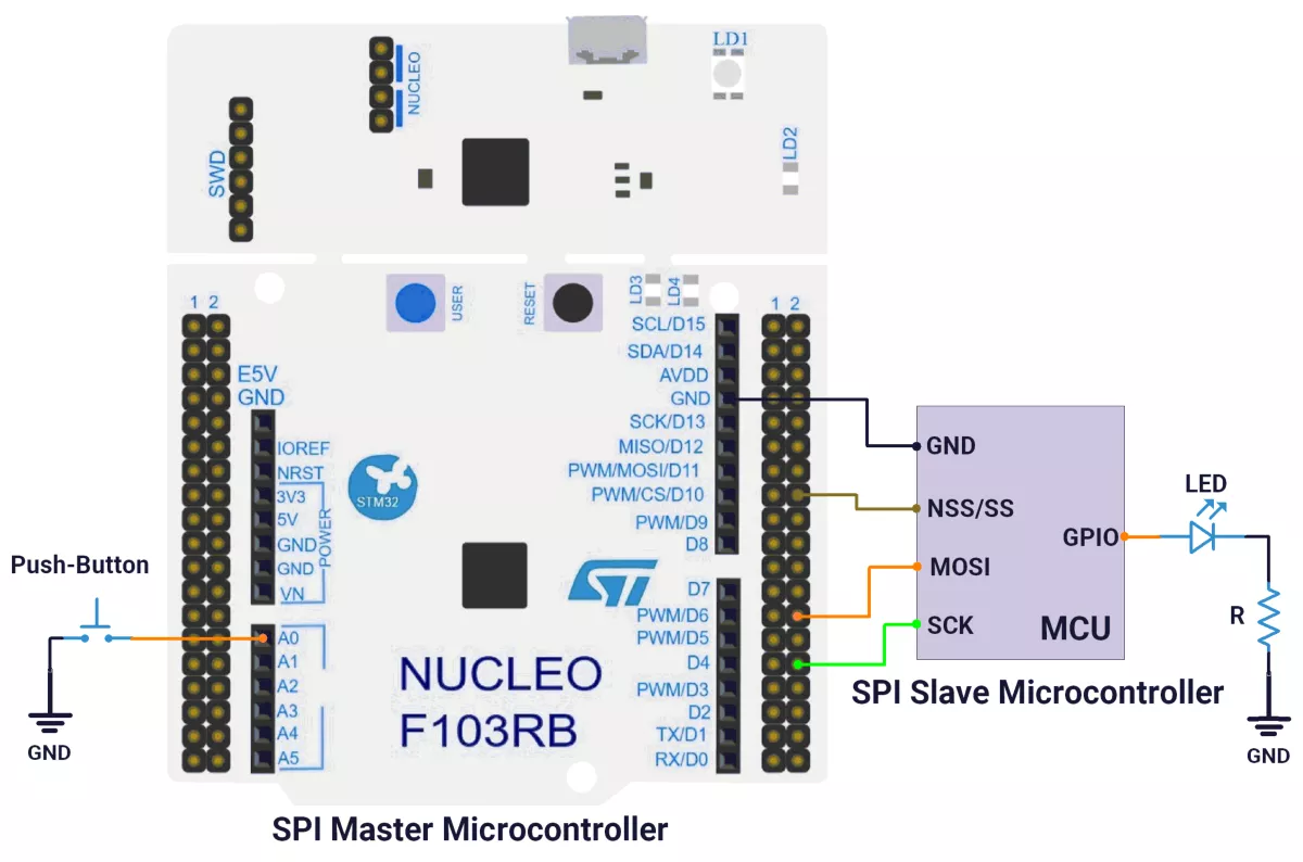
Master Board (NUCLEO-F103RB)
- Push-button: PA0 (A0) configured as input with pull-up.
- SPI2 pins:
- PB13: SCK
- PB15: MOSI
- PB12: NSS/CS (GPIO output, controlled low during transfers)
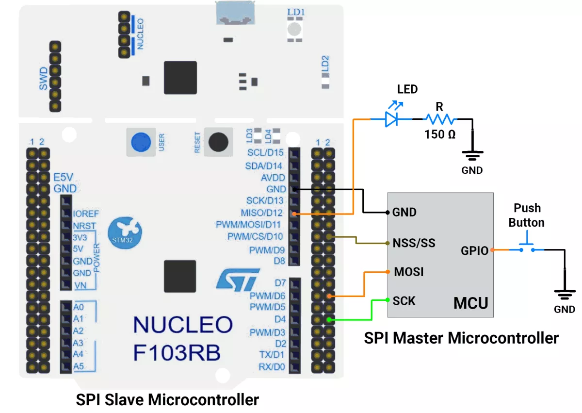
Slave Board (NUCLEO-F103RB)
- LED: PA6 (D12) configured as output
- SPI2 pins:
- PB13: SCK (input)
- PB15: MOSI (input)
- PB12: NSS (input)
Circuit Diagram
A) STM32 as a Master:
B) STM32 as a Slave:
Firmware Implementation
A) STM32 as a Master:
Project Setup in STM32CubeIDE
- Create a Project
- Open STM32CubeIDE, start a new project, and select the NUCLEO-F103RB board.
- Basic Configuration (via CubeMX inside CubeIDE)
- Clock: Use the default HSI oscillator with PLL enabled (as configured in
SystemClock_Config). - GPIO: Enable clocks for PORTA, PORTB, PORTC, and PORTD.
- Push-Button: Set GPIO PA0 as GPIO Input Pull-Up
- NSS Pin: Set GPIO PB12 as GPIO Output Push-Pull
- SPI2 Configuration:
- Mode: Transmit Only Master (
SPI_MODE_MASTER) - Data Size: 8-bit (
SPI_DATASIZE_8BIT) - Clock Polarity: Low (
SPI_POLARITY_LOW) - Clock Phase: Data sampled on first edge (
SPI_PHASE_1EDGE) - NSS (Slave Select): Software-controlled (
SPI_NSS_SOFT) - Baud Rate: Prescaler 32
- Data Order: MSB first (
SPI_FIRSTBIT_MSB) - CRC & TI Mode: Disabled
- Mode: Transmit Only Master (
- USART2: Enabled at 115200 baud, 8-N-1.
- Clock: Use the default HSI oscillator with PLL enabled (as configured in
- Code Generation
- CubeMX will automatically generate all the startup code, including:
HAL_Init()→ Initializes HAL and system tick.SystemClock_Config()→ Configures system clock (HSI + PLL).MX_GPIO_Init()→ Initializes GPIO ports.MX_USART2_UART_Init()→ Configures UART2.MX_SPI2_Init()→ Configures SPI2.
- This code sets up the hardware and prepares the project for firmware development, so we only need to add our application logic in the user code sections
- CubeMX will automatically generate all the startup code, including:
Code Snippets from main.c
SPI Initialization (Generated by CubeMX)
 /* SPI2 parameter configuration*/
  hspi2.Instance = SPI2;
  hspi2.Init.Mode = SPI_MODE_MASTER;
  hspi2.Init.Direction = SPI_DIRECTION_2LINES;
  hspi2.Init.DataSize = SPI_DATASIZE_8BIT;
  hspi2.Init.CLKPolarity = SPI_POLARITY_LOW;
  hspi2.Init.CLKPhase = SPI_PHASE_1EDGE;
  hspi2.Init.NSS = SPI_NSS_SOFT;
  hspi2.Init.BaudRatePrescaler = SPI_BAUDRATEPRESCALER_32;
  hspi2.Init.FirstBit = SPI_FIRSTBIT_MSB;
  hspi2.Init.TIMode = SPI_TIMODE_DISABLE;
  hspi2.Init.CRCCalculation = SPI_CRCCALCULATION_DISABLE;
  hspi2.Init.CRCPolynomial = 10;
  if (HAL_SPI_Init(&hspi2) != HAL_OK)
  {
    Error_Handler();
  }
Initializes SPI2 in master mode with 2-line (MOSI) communication, 8-bit data, low polarity, 1st edge clock phase, software-controlled chip select (CS), and a baud rate prescaler of 32.


Header includes and Private defines

#include <stdbool.h>

#define SPI2_CS_PIN GPIO_PIN_12
#define SPI2_CS_PORT GPIOB

#define SWITCH_PIN GPIO_PIN_0
#define SWITCH_PORT GPIOA
Defines pin and port mappings for SPI2 chip select (CS) and a switch input (GPIO).
SPI Transmission
void SPI2_TransmitByte(uint8_t data) {
  SPI2_CS_Enable(true);  // Pull CS low
  HAL_SPI_Transmit(&hspi2, &data, 1, HAL_MAX_DELAY);
  SPI2_CS_Enable(false); // Pull CS high
}
Transmits a single byte over SPI2, toggling the CS pin (low before, high after transmission).
CS Control
void SPI2_CS_Enable(bool enable) {
  HAL_GPIO_WritePin(SPI2_CS_PORT, SPI2_CS_PIN, enable ? GPIO_PIN_RESET : GPIO_PIN_SET);
}
Controls the SPI2 CS pin state (low = enable, high = disable).
Main Loop (Button-Triggered SPI Transmission)
uint8_t txData = 0x00;
while (1) {
  if (HAL_GPIO_ReadPin(SWITCH_PORT, SWITCH_PIN) == GPIO_PIN_RESET) {
    SPI2_TransmitByte(txData); // Send data
    txData ^= 1; // Toggle between 0x00 and 0x01
    HAL_Delay(300); // Simple debounce
  }
}
Checks a button press; if triggered, sends a toggling byte (0x00/0x01) via SPI and adds a 300ms debounce delay.
Expected Output
- When the button is pressed, the STM32 transmits
0x00 or 0x01alternately over SPI. - The slave device (e.g., shift register) should toggle an LED accordingly.
Download Project
The complete STM32CubeIDE project (including .ioc configuration, main.c, and HAL files) is available here:
📥 Download Project
B) STM32 as a Slave:
Project Setup in STM32CubeIDE
- Create a Project
- Open STM32CubeIDE, start a new project, and select the NUCLEO-F103RB board.
- Basic Configuration (via CubeMX inside CubeIDE)
- Clock: Use the default HSI oscillator with PLL enabled (as configured in
SystemClock_Config). - GPIO: Enable clocks for PORTA, PORTB, PORTC, and PORTD.
- LED: Set GPIO PA6 as GPIO Output Push-Pull in the Pinout view
- NSS Pin: Set GPIO PB12 as a GPIO Input Pull-Up
- SPI2 Configuration:
- Mode: Receive Only Slave (SPI_MODE_SLAVE)
- Hardware NSS Signal: Hardware NSS Input Signal
- Data Line: 2-line RX only (SPI_DIRECTION_2LINES_RXONLY)
- Data Size: 8-bit (SPI_DATASIZE_8BIT)
- Clock Polarity: Low (SPI_POLARITY_LOW)
- Clock Phase: Data sampled on first edge (SPI_PHASE_1EDGE)
- NSS (Slave Select): Hardware-controlled (SPI_NSS_HARD_INPUT)
- Data Order: MSB first (SPI_FIRSTBIT_MSB)
- CRC & TI Mode: Disabled
- Interrupt: Enable SPI2 Global Interrupt in NVIC for non-blocking reception.
- USART2: Enabled at 115200 baud, 8-N-1.
- Clock: Use the default HSI oscillator with PLL enabled (as configured in
- Code Generation
- CubeMX will automatically generate all the startup code, including:
HAL_Init()→ Initializes HAL and system tick.SystemClock_Config()→ Configures system clock (HSI + PLL).MX_GPIO_Init()→ Initializes GPIO ports.MX_USART2_UART_Init()→ Configures UART2.MX_SPI2_Init()→ Configures SPI2.
- This code sets up the hardware and prepares the project for firmware development, so we only need to add our application logic in the user code section.
- CubeMX will automatically generate all the startup code, including:
SPI Initialization (Generated by CubeMX)
 /* SPI2 parameter configuration*/
  hspi2.Instance = SPI2;
  hspi2.Init.Mode = SPI_MODE_SLAVE;
  hspi2.Init.Direction = SPI_DIRECTION_2LINES_RXONLY;
  hspi2.Init.DataSize = SPI_DATASIZE_8BIT;
  hspi2.Init.CLKPolarity = SPI_POLARITY_LOW;
  hspi2.Init.CLKPhase = SPI_PHASE_1EDGE;
  hspi2.Init.NSS = SPI_NSS_HARD_INPUT;
  hspi2.Init.FirstBit = SPI_FIRSTBIT_MSB;
  hspi2.Init.TIMode = SPI_TIMODE_DISABLE;
  hspi2.Init.CRCCalculation = SPI_CRCCALCULATION_DISABLE;
  hspi2.Init.CRCPolynomial = 10;
  if (HAL_SPI_Init(&hspi2) != HAL_OK)
  {
    Error_Handler();
  }
Initializes SPI2 in slave mode with 2-line receive-only communication, 8-bit data, low polarity, 1st edge clock phase, and hardware-controlled chip select.
Private defines
#define LED_PORT GPIOA
#define LED_PIN GPIO_PIN_6

#define SPI_SLAVE_NSS_PIN GPIO_PIN_12
#define SPI_SLAVE_NSS_PORT GPIOB
Defines pin and port mappings for SPI2 chip select (CS) and an LED output (GPIO).
SPI Reception Callback
void HAL_SPI_RxCpltCallback(SPI_HandleTypeDef *hspi) {
    dataReady = 1;
    // Restart reception
    HAL_SPI_Receive_IT(&hspi2, &receivedData, 1);
}
Handles received data and immediately restarts reception in interrupt mode.
Main Loop (Button-Triggered SPI Transmission)
while (1) {
    if (dataReady) {
        dataReady = 0;

        // Control LED based on received data
        if (receivedData == 0x01) {
            HAL_GPIO_WritePin(LED_PORT, LED_PIN, 1); // LED ON
        } else if (receivedData == 0x00) {
            HAL_GPIO_WritePin(LED_PORT, LED_PIN, 0); // LED OFF
        }
    }
    HAL_Delay(1);
}
Controls an LED based on received SPI data (0x01 turns LED on, 0x00 turns it off).
Expected Output
- The STM32 acts as an SPI slave, continuously listening for incoming data
- When data 0x01 is received, the onboard LED (PA6) turns on
- When data 0x00 is received, the LED turns off
- The device uses interrupt-based reception for efficient operation
Download Project
The complete STM32CubeIDE project (including .ioc configuration, main.c, and HAL files) is available here:
📥 Download Project
We are using the ESP32 DevKit v4 development board and programming it using the Arduino IDE.
- Before uploading, make sure to select “ESP32 Dev Module” as the board to ensure correct settings and compatibility.
Solution of the given task:
- ESP32 as Master
- ESP32 as Slave
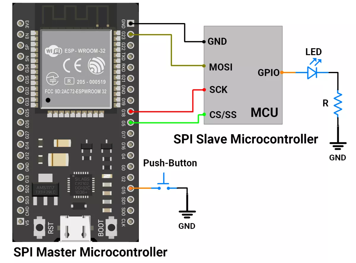
A) ESP32 as Master
ESP32 Circuit Connection
- Interface push button switch to GPIO pin 15.
- Interface master SPI pins to the slave SPI pin
- GPIO PIN 18 → SCK
- GPIO PIN 19 → MISO
- GPIO PIN 23 → MOSI
- GPIO PIN 5 → CS/SS
- Interface the LED to the slave device with a current-limiting resistor.
ESP32 Firmware Implementation
In the ESP32 master code, the SPI.h library is used for SPI communication.
Master Code
#include <SPI.h>

// Pin definitions
#define SS_PIN 5       // Slave Select (CS) pin
#define SWITCH_PIN 15  // Push button pin

// State variables
bool ledState = false;              // LED ON/OFF state to send
const uint8_t DEBOUNCE_DELAY = 50;  // Debounce time in ms

// Button state tracking
unsigned long lastDebounceTime = 0;
uint8_t lastButtonState = HIGH;  // Last stable button state
uint8_t buttonState = HIGH;      // Current button state

void setup() {
  pinMode(SS_PIN, OUTPUT);            // SS pin as output
  pinMode(SWITCH_PIN, INPUT_PULLUP);  // Button with pull-up

  Serial.begin(115200);  // Debug output

  // Initialize SPI (SCLK=18, MISO=19, MOSI=23, SS=5)
  SPI.begin(18, 19, 23, SS_PIN);

  digitalWrite(SS_PIN, HIGH);  // Keep slave deselected
}

void loop() {
  // If button is pressed after debounce
  if (isButtonPressed()) {
    ledState = !ledState;  // Toggle state

    digitalWrite(SS_PIN, LOW);  // Select slave

    // Send command: 0x01 = LED ON, 0x00 = LED OFF
    SPI.transfer(ledState ? 0x01 : 0x00);
    Serial.printf("Sent: 0x%02X\n", ledState ? 0x01 : 0x00);

    digitalWrite(SS_PIN, HIGH);  // Deselect slave
  }
}

// Debounce function for push button
bool isButtonPressed() {
  int reading = digitalRead(SWITCH_PIN);

  if (reading != lastButtonState) {  // If state changed
    lastDebounceTime = millis();     // Reset debounce timer
  }
  lastButtonState = reading;

  // If stable for longer than debounce delay
  if ((millis() - lastDebounceTime) > DEBOUNCE_DELAY) {
    if (reading != buttonState) {  // New stable state
      buttonState = reading;
      if (buttonState == LOW) {  // Button pressed
        return true;
      }
    }
  }
  return false;
}
Code Explanation
Setup
- Configure SPI pins (SCLK=18, MISO=19, MOSI=23, SS=5).
- Set button with pull-up and SS pin as output.
- Keep slave deselected by
digitalWrite(SS_PIN, HIGH);
Loop
- Continuously check if the button is pressed (with debounce).
- If pressed → toggle
ledState(ON ↔ OFF). - Select slave by making SS pin low (
digitalWrite(SS_PIN, LOW);). - Send
0x01if ON,0x00if OFF viaSPI.transfer(). - Deselect slave by
digitalWrite(SS_PIN, HIGH);
isButtonPressed()
- Reads the button state and resets a timer if it changes.
- Confirms the state only if stable for longer than
DEBOUNCE_DELAY. - Returns true when a valid LOW press is detected.
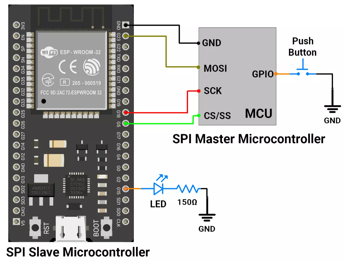
B) ESP32 as Slave
ESP32 Circuit Connection
- Interface LED with GPIO pin 15 with a Current-limiting resistor of 150 ohms.
- Interface slave SPI pins to the master SPI pin
- GPIO PIN 18 → SCK
- GPIO PIN 19 → MISO
- GPIO PIN 23 → MOSI
- GPIO PIN 5 → CS/SS
- Interface push button switch to the GPIO pin of the Master controller.
ESP32 Firmware Implementation
For the slave code, we used #include "driver/spi_slave.h" driver file.
Slave Code
#include "driver/spi_slave.h"

// Pin definitions
#define LED_PIN 15        // LED output pin
#define PIN_MOSI 23       // Master Out, Slave In(MOSI)
#define PIN_MISO 19       // Master In, Slave Out(MIS)
#define PIN_SCLK 18       // Serial Clock
#define PIN_CS   5        // Chip Select (from master)

// Buffers
uint8_t recv_buf[1];         // Data received from master
uint8_t send_buf[1] = {0xAA}; // Dummy byte to send back
uint8_t data = 0;            // Stores received byte

void setup() {
  Serial.begin(115200);
  pinMode(LED_PIN, OUTPUT);
  digitalWrite(LED_PIN, HIGH); // Turn LED on at start

  // Configure SPI bus pins
  spi_bus_config_t buscfg = {
    .mosi_io_num = PIN_MOSI,
    .miso_io_num = PIN_MISO,
    .sclk_io_num = PIN_SCLK,
    .quadwp_io_num = -1,   // Not used
    .quadhd_io_num = -1,   // Not used
    .max_transfer_sz = 1   // Max transfer size = 1 byte
  };

  // Configure SPI slave interface
  spi_slave_interface_config_t slvcfg = {
    .spics_io_num = PIN_CS, // CS pin
    .flags = 0,
    .queue_size = 1,        // One transaction at a time
    .mode = 0,              // SPI mode 0 (CPOL=0, CPHA=0)
    .post_setup_cb = NULL,
    .post_trans_cb = NULL
  };

  // Initialize SPI slave driver
  if (spi_slave_initialize(VSPI_HOST, &buscfg, &slvcfg, SPI_DMA_DISABLED) != ESP_OK) {
    Serial.println("SPI Slave init failed!");
    return;
  }

  Serial.println("SPI Slave Ready");
}

void loop() {
  // Define SPI transaction (1 byte in/out)
  spi_slave_transaction_t trans = {
    .length = 8,             // 8 bits
    .tx_buffer = send_buf,   // Send dummy byte
    .rx_buffer = recv_buf    // Receive data
  };

  // Block until master sends data
  if (spi_slave_transmit(VSPI_HOST, &trans, portMAX_DELAY) == ESP_OK) {
    data = recv_buf[0];  // Store received byte
    Serial.printf("Received: 0x%02X\n", data);

    // LED control: ON if 0x01 received, else OFF
    digitalWrite(LED_PIN, data == 0x01 ? HIGH : LOW);
  }
}
Code Explanation
Setup Loop
- ESP32 is configured as an SPI slave with defined MOSI, MISO, SCLK, and CS pins.
- An LED is set as output.
- Buffers are prepared: one for receiving (
recv_buf), one for sending (send_buf = 0xAA).
Loop Loop
- ESP32 waits until the master sends 1 byte (
spi_slave_transmit). - When data is received, it is stored in
recv_buf[0]. - If the received byte =
0x01, LED turns ON; otherwise, LED turns OFF. - At the same time, ESP32 always sends back
0xAAto the master (dummy response).
We are using the Arduino UNO development board and programming it using the Arduino IDE.
- Before uploading, make sure to select “Arduino UNO” as the board to ensure correct settings and compatibility.
In both Arduino UNO master and slave codes, the SPI.h library is used for SPI communication.
SPI Pins Of Arduino UNO
- SCK → 13
- MISO → 12
- MOSI → 11
- SS → 10
Solution of the given task:
- Arduino UNO as Master
- Arduino UNO as Slave
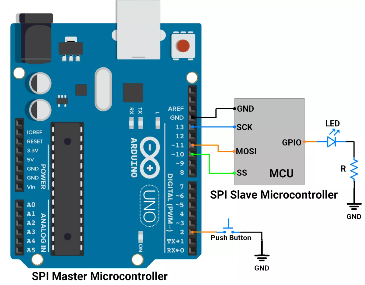
A) Arduino UNO as a master
First, let's establish the hardware connection.
Arduino UNO Hardware Connection
- Interface push button switch to GPIO pin 2.
- Connect the SPI pins(SCK, MOSI, SS) of the master to the SPI pins of the slave.
- As communication is unidirectional, master to slave, we are not connecting the MISO line.
- Interface the LED to the slave device with a current-limiting resistor.
Circuit Diagram
Arduino UNO Firmware Implementation
- Setup: Configures SPI, push button, and SS pin.
- Button Press: Detects valid button presses with debouncing.
- Command Sending: Toggles
ledState(ON/OFF) and sends 0x01(ON) or 0x00(OFF) to the slave via SPI.
Code (Master)
#include <SPI.h>

#define SS_PIN 10     // Slave Select pin for SPI
#define SWITCH_PIN 2  // Push button pin

// Variables for button handling
bool ledState = false;  // Tracks the LED state (ON/OFF)

const uint8_t DEBOUNCE_DELAY = 50;  // Debounce delay in milliseconds

// Button state variables
unsigned long lastDebounceTime = 0;  // Last recorded debounce time
uint8_t lastButtonState = HIGH;      // Last stable state of the button
uint8_t buttonState = HIGH;          // Current state of the button

void setup() {
  pinMode(SS_PIN, OUTPUT);            // Set Slave Select (SS) pin as output
  pinMode(SWITCH_PIN, INPUT_PULLUP);  // Set push button pin as input with pull-up resistor

  // Initialize SPI communication
  SPI.begin();                 // Start SPI
  digitalWrite(SS_PIN, HIGH);  // Ensure SS is HIGH (deselect the slave)
  Serial.begin(115200);
}

void loop() {
  // Check if the button is pressed
  if (isButtonPressed()) {
    // Toggle the LED state
    ledState = !ledState;

    // Begin SPI communication with the slave
    digitalWrite(SS_PIN, LOW);  // Pull SS low to select the slave

    if (ledState) {
      SPI.transfer(0x01);  // Send ON command (0x01) to the slave
    } else {
      SPI.transfer(0x00);  // Send OFF command (0x00) to the slave
    }

    digitalWrite(SS_PIN, HIGH);  // Deselect the slave by setting SS high
  }
}

/**
 * Checks if the button is pressed with debouncing.
 *
 * @return true if a valid button press is detected, false otherwise.
 */
bool isButtonPressed() {
  int reading = digitalRead(SWITCH_PIN);

  // If the button state has changed since the last read
  if (reading != lastButtonState) {
    lastDebounceTime = millis();  // Update debounce timer
  }
  lastButtonState = reading;

  // If the button state remains stable for the debounce delay period
  if ((millis() - lastDebounceTime) > DEBOUNCE_DELAY) {
    // If the button state has changed
    if (reading != buttonState) {
      buttonState = reading;

      // Return true if the button is pressed (LOW state)
      if (buttonState == LOW) {
        return true;
      }
    }
  }

  // Return false if no valid press is detected
  return false;
}
Code Explanation(Master)
- Initialization (setup)
- Set up the SPI interface.
- Configures the button (
SWITCH_PIN) as input with an internal pull-up resistor. - Sets the Slave Select (
SS_PIN) as an output and ensures it starts in the inactive state (HIGH).
- Main Loop (loop)
- Continuously checks for button presses using the
isButtonPressed()function. - If a valid button press is detected:
- Toggles the ledState variable.
- Sends the corresponding command (0x01 for ON or 0x00 for OFF) to the Slave via SPI.
- Handles the Slave Select (SS_PIN) to manage communication with the Slave.
- Continuously checks for button presses using the
- Debounce Function (
isButtonPressed())- Reads the button state and verifies stability over a defined debounce period (
DEBOUNCE_DELAY). - Ensures that only valid button presses trigger the LED state toggle.
- Reads the button state and verifies stability over a defined debounce period (
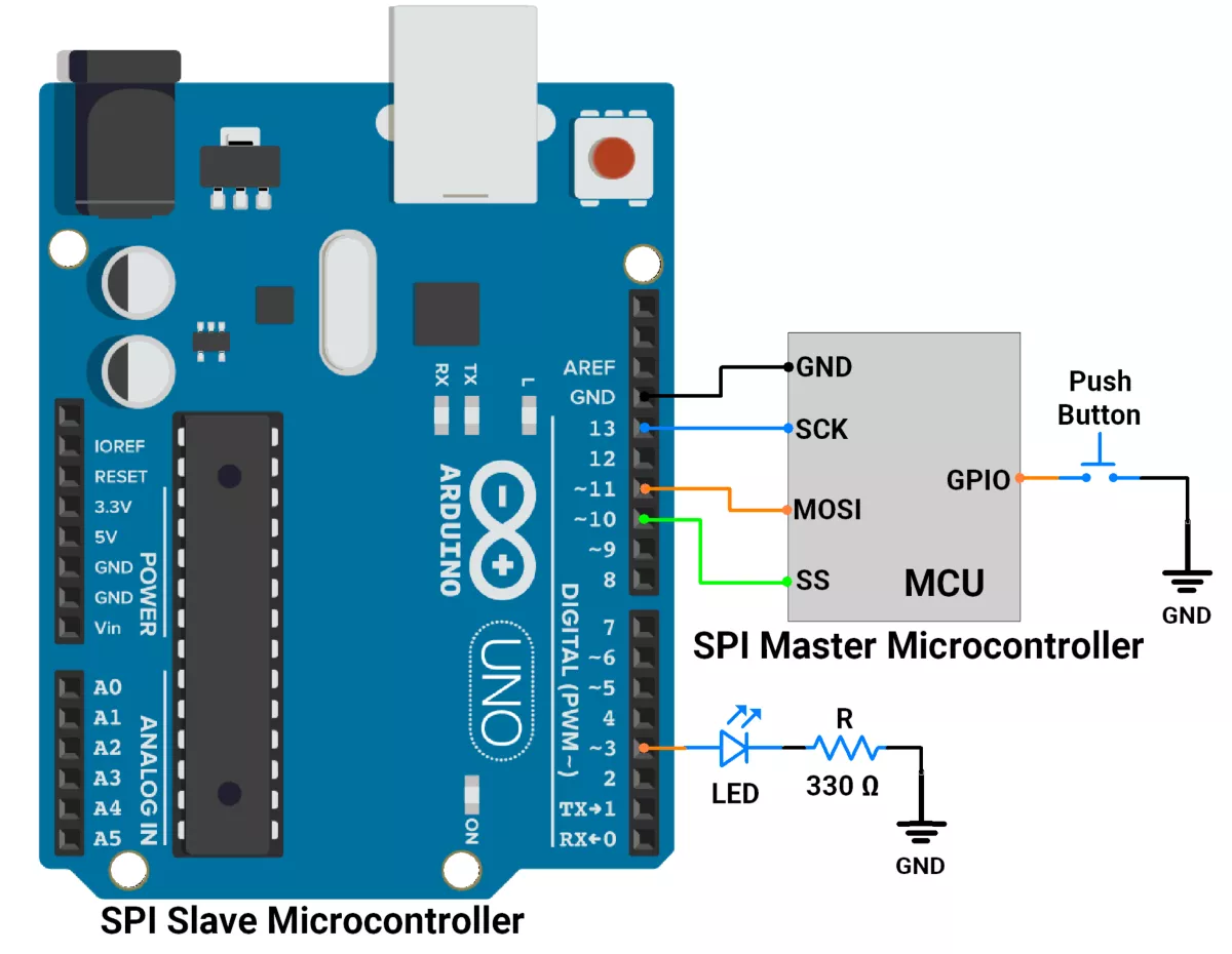
B) Arduino UNO as a slave
First, let's establish the hardware connection.
Arduino UNO Hardware Connection
- Interface LED with a GPIO pin 3 with a Current-limiting resistor of 330 ohms.
- Connect the SPI pins(SCK, MOSI, SS) of the slave to the SPI pins of the master.
- As communication is unidirectional, master to slave, we are not connecting the MISO line.
- Interface push button switch to the GPIO pin of the Master controller.
Arduino UNO Circuit Diagram
Arduino UNO Firmware Implementation
- Setup: Configures SPI, LED pin, and interrupt for SPI communication.
- Data Reception: Listens for data from the SPI master using an interrupt.
- Command Processing: When data (0x01 or 0x00) is received, the flag is set to indicate data availability.
- LED Control: In the main loop, the command is processed, and the LED is turned ON (0x01) or OFF (0x00) based on the received data.
Code (Slave)
#include <SPI.h>

#define LED_PIN 3                // LED connected to Pin 3
volatile byte receivedData = 0;  // Variable to store received data from SPI
bool flag = 0;                   // Flag to indicate data received

void setup() {
  pinMode(LED_PIN, OUTPUT);    // Set LED pin as output
  digitalWrite(LED_PIN, LOW);  // Ensure LED is OFF initially
  Serial.begin(115200);
  // Configure SPI in slave mode
  pinMode(MISO, OUTPUT);  // Set MISO (Master In Slave Out) as output
  SPCR |= _BV(SPE);       // Enable SPI in slave mode

  // Attach SPI interrupt for data reception
  SPI.attachInterrupt();  // Enable SPI interrupt
}

/**
 * Interrupt Service Routine (ISR) for SPI communication
 * This gets triggered whenever data is received via SPI.
 */
ISR(SPI_STC_vect) {
  receivedData = SPDR;  // Read received data from SPI Data Register
  flag = 1;             // Set flag to indicate data received
}

void loop() {
  // Check if data has been received
  if (flag) {
    // Control LED based on received data
    if (receivedData == 0x01) {
      digitalWrite(LED_PIN, HIGH);  // Turn ON LED if data is 0x01
    } else if (receivedData == 0x00) {
      digitalWrite(LED_PIN, LOW);  // Turn OFF LED if data is 0x00
    }

    flag = 0;  // Reset flag after processing the data
  }
}
Code Explanation(Slave)
1. Setup:
- The LED pin is configured as an output, and the LED is turned OFF initially.
- SPI is configured in slave mode, and the MISO pin is set as an output.
- The SPI interrupt is enabled to listen to incoming data.
2. Interrupt Routine:
- When the Master sends data, the ISR reads it from the SPI Data Register (
SPDR) and sets the flag to indicate data reception.
3. Main Loop:
- The
loop()function continuously checks the flag. - If the flag is set, it processes the received data to control the LED state and then resets the flag.
Output
Hardware Setup
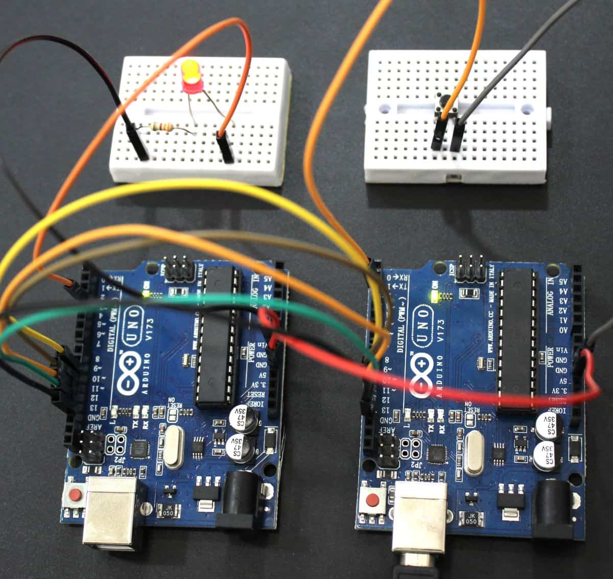
Output Video
We can see in the video, that as we click the button on the master the LED connected to the slave is toggling.