
41. SPI Dice Roll
Build an SPI Master using any microcontroller to establish communication with an SPI Slave.
Task Description:
- The SPI Slave acts as a digital dice roller, generating a random number between 1 and 6 whenever it receives a request from the master.
- A push-button switch is connected to the master. When the button is pressed, the master sends a request to the slave via SPI communication.
- The slave responds with the generated random dice value.
- The master then prints the received dice value on a serial terminal (e.g., PuTTY or the Arduino IDE Serial Monitor).
Note:
The SPI Slave (dice roller) must operate in SPI Mode 2.
Only the Master code needs to be developed for this task.
Example Slave Code for demonstration (Arduino UNO Dice Roller)
The following example demonstrates an Arduino-based SPI Slave configured in SPI Mode 2.
#include <SPI.h>

void setup() {
  pinMode(MISO, OUTPUT);  // Set MISO as OUTPUT to send data to the master

  // Enable SPI in slave mode
  SPCR |= _BV(SPE);

  // Send SPI data in mode 2
  SPI.setDataMode(SPI_MODE2);

  // Attach SPI interrupt
  SPI.attachInterrupt();

  // Generate a random number and store it to transmit during SPI communication.
  SPDR = random(1, 7);
}

ISR(SPI_STC_vect) {
  // Generate a random number and send it.
  SPDR = random(1, 7);
}

void loop() {
}
Example Serial monitor output:

SPI Basics
SPI(Serial Peripheral Interface) is a High-Speed, synchronous, full-duplex, serial Communication protocol.
- Short distance protocol: distance <10cm.
- High Speed: Faster than I2C and UART ( 1MHz - 200MHz range - depends on controller clock- default 4MHz in Arduino UNO).
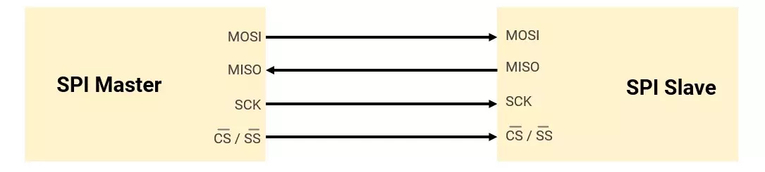
SPI communication is commonly used to interface such as Memory devices (SD cards, EEPROM, Flash), displays(OLED), sensors, and ADC/DAC.
SPI Pins (4-pin)
| Signal | Full Name | Direction | Description |
|---|---|---|---|
| SCK | Serial Clock | Master → Slave | Generated by the master to synchronise data transfer |
| MOSI | Master Out Slave In | Master → Slave | Data from master to slave |
| MISO | Master In Slave Out | Slave → Master | Data from slave to master |
| SS/CS | Slave Select / Chip Select | Master → Slave | Selects which slave is active (Active-Low) |
No Addressing for Slave- SPI uses chip select (SS) lines to select slaves.
SPI Modes
SPI has 4 modes, determined by CPOL (Clock Polarity) and CPHA (Clock Phase).
- Clock Polarity (CPOL) – Defines the idle state of the clock. (LOW or HIGH)
- Clock Phase (CPHA) – Determines when data is sampled (read) (On the RISING edge or the FALLING edge).
| Mode | CPOL | CPHA | Clock Idle State | Data Sampled On |
|---|---|---|---|---|
| 0 | 0 | 0 | Low | Rising Edge |
| 1 | 0 | 1 | Low | Falling Edge |
| 2 | 1 | 0 | High | Falling Edge |
| 3 | 1 | 1 | High | Rising Edge |
SPI Mode Diagram
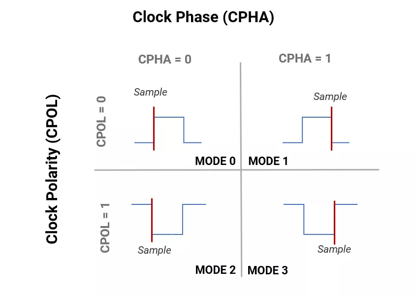
Example
Mode 0- In SPI Mode 0 (CPOL=0, CPHA=0), clock polarity is low when idle; data is sampled on the rising edge as shown in the given diagram.
Data sampling w.r.t clock polarity and phase.
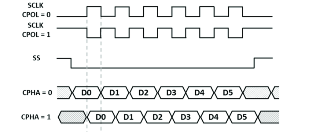
SPI Data Transfer
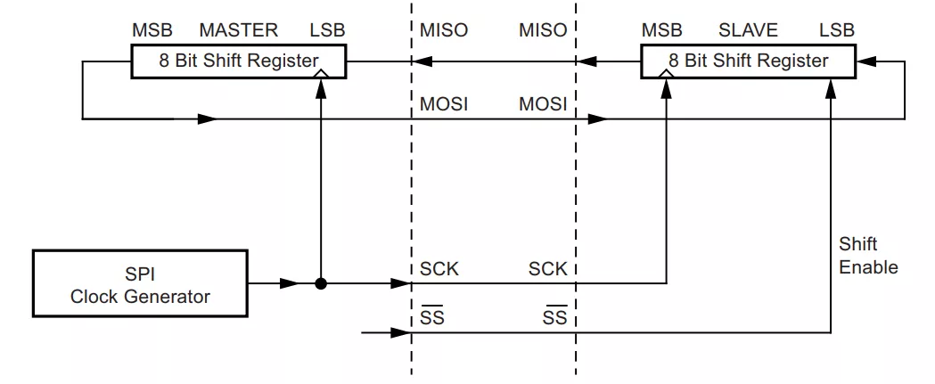
- Master pulls SS/CS LOW to start communication with a particular slave.
- It is a full-duplex communication protocol, so both master and slave send and receive data bit by bit serially at the same time in synchronization with clock.
- If the master only wants to read from the slave, it must send dummy data to the slave's response.
- Data transfer in SPI is both directional ( MSB to LSB or LSB to MSB).
Daisy-Chaining Method (Multi-Slave Configuration)
- This method connects all SPI slaves in series, shifting data continuously through all devices during SCK pulses.
- Each slave latches its assigned data portion either on the CS edge (most common) or after a fixed bit count, enabling simultaneous data propagation and per-slave capture.
- A single shared SCK and SS line minimizes hardware complexity.
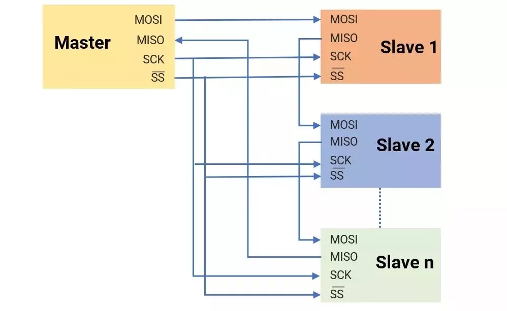
Note: This protocol is not designed for a multi-master configuration by default.
SPI in Micro-Controllers
SPI is an on-board protocol found in most controllers ( AVR, PIC, ARM, and RISC).
Generally following registers are present in controllers. (with reference to AVR ATmega 328P)
| Registers | Description |
|---|---|
| SPCR | SPI Control Register: enabling SPI and interrupt, selecting Master/Slave mode, clock polarity (CPOL), phase (CPHA), and data order (MSB/LSB first) |
| SPISR | SPI Status Register: flags(SPIF, WCOL) help manage and monitor SPI communication and double the Speed in SPI. |
| SPDR | SPI Data Register - writing/ reading data buffer for SPI communication |
Writing SPI Driver (Master- Writing Data)
- Set SPI pins: Configure MOSI, SCK, and SS as outputs; MISO as input.
- Enable SPI: Configure the SPI control register to enable SPI and select master mode.
- Set clock: Configure clock polarity, phase, and speed in the SPI control register.
- Send data: Write to the SPI buffer to start transmission. Read data: Read received data from the SPI buffer.
SPI in Arduino UNO
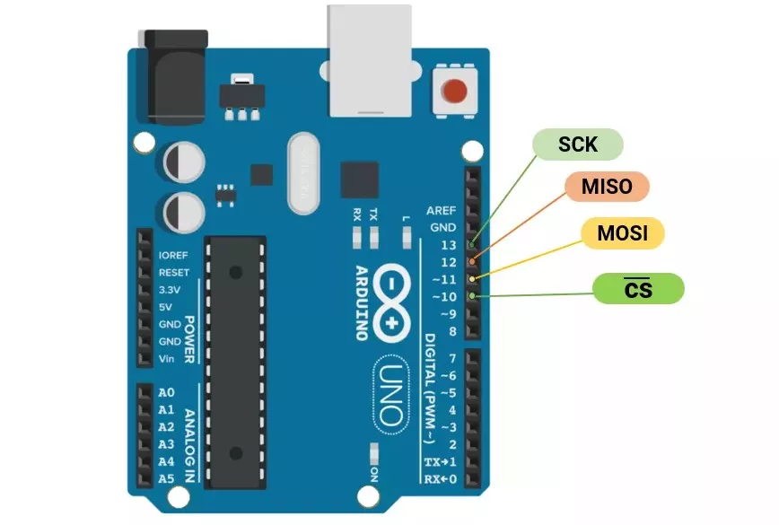
SPI communication pins in Arduino UNO
Arduino SPI.h Library Functions
| Functions | Descriptions |
|---|---|
SPI. begin() | Initializes the SPI bus by setting SCK, MOSI, and SS to outputs |
SPI. beginTransaction(mySettings) | Initializes the SPI bus. Note that calling SPI.begin() is required before calling this one. |
mySetting(speedMaximum, dataOrder, dataMode) | SPISettings object is used with SPI.beginTransaction() for configuration. |
SPI. endTransaction() | Stop using the SPI bus. |
SPI. end() | Disables the SPI bus (leaving pin modes unchanged). |
SPI. setBitOrder(order) | Sets the order of the bits shifted out. |
SPI. setClockDivider(divider) | Sets the SPI clock divider relative to the system clock. |
SPI. setDataMode(mode) | Sets the SPI data mode. |
SPI. transfer() | Transfer and receipt of the data. |
SPI. usingInterrupt() | Inform the SPI library to avoid conflicts with a specific interrupt. |
Example
Master sends 0x80 to the slave using SPI.
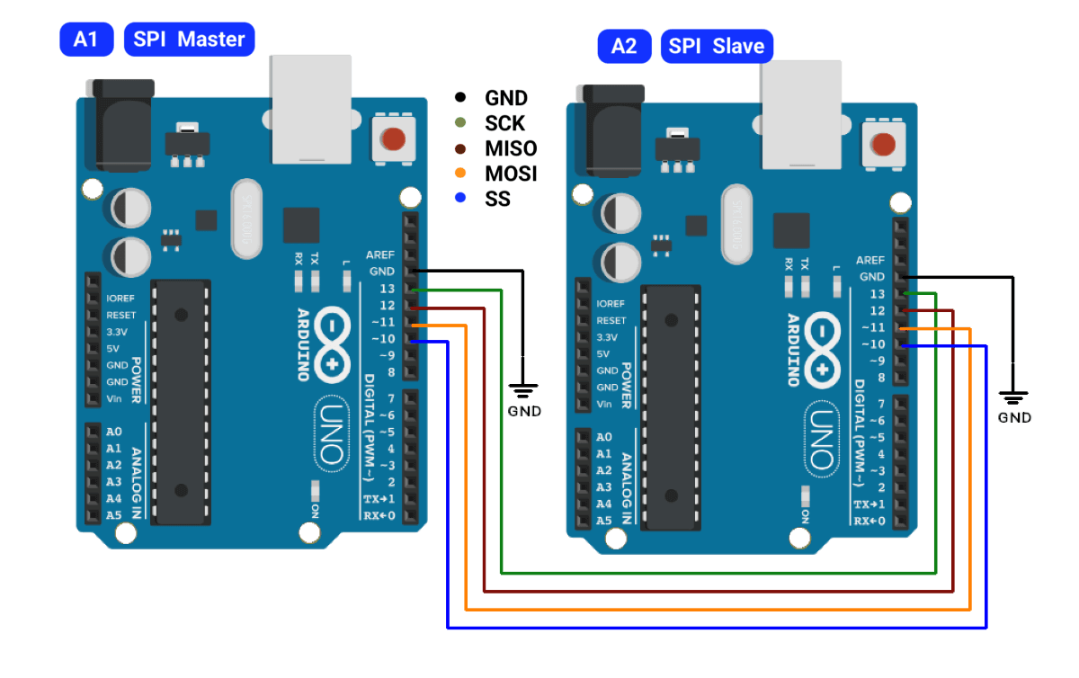
Master Code(A1)
#include <SPI.h>

void setup() {
  SPI.begin();             // Initialize SPI bus
  pinMode(SS, OUTPUT);     // Set SS pin as output
  digitalWrite(SS, HIGH);  // Deselect slave initially
  Serial.begin(9600);      // For debug (optional)
}

void loop() {
  digitalWrite(SS, LOW);               // Select slave
  byte received = SPI.transfer(0x80);  // Send 0x80 and read response
  digitalWrite(SS, HIGH);              // Deselect slave

  Serial.print("Sent: 0x80 | Received: 0x");
  Serial.println(received, HEX);  // Print slave's response

  delay(1000);  // Wait 1 second
}
Slave Code(A2)
#include <SPI.h>

volatile byte receivedData;

void setup() {
  Serial.begin(9600);
  pinMode(MISO, OUTPUT);    // Set MISO as output (Slave)
  SPCR |= (1 << SPE);       // Enable SPI (Slave mode)
  SPCR |= (1 << SPIE);      // Enable SPI Interrupt
}

ISR(SPI_STC_vect) {        // SPI Interrupt Service Routine
  receivedData = SPDR;      // Store received byte
  Serial.print("Received: 0x");
  if (receivedData < 0x10)
    Serial.print("0"); // Pad single digit hex
  Serial.println(receivedData, HEX); // Print in HEX
}

void loop() {
  // Do nothing (SPI runs via interrupt)
}