19. Seesaw Effect Using LEDs
After analyzing the task,
We need to connect five LEDs and a potentiometer to the microcontroller. The idea is to make their brightness change based on the potentiometer’s position so that it creates a seesaw effect.
How will the LED brightness adjust as per the potentiometer?
The potentiometer value (0%–100%) is mapped to PWM duty cycles of each LED so that each LED follows the required brightness pattern to create a seesaw effect:
LED brightness for the full range of potentiometer(0% → 100%):
- LED0: 0% → 100%
- LED1: 25% → 75%
- LED2: fixed at 50%
- LED3: 75% → 25%
- LED4: 100% → 0%
We’ll use PWM to control each LED’s brightness, and the ADC value from the potentiometer will be mapped to the duty cycle for each LED.
For example, consider a 10-bit PWM resolution (0–1023) and the potentiometer spanning the same range (0–1023):
- LED1 is restricted between 25% and 75% duty cycle, i.e., 256 to 767 PWM counts.
- As the potentiometer moves from 0 to 1023, LED1’s duty cycle only varies within 25% and 75% range, ensuring its brightness stays between 25% and 75%.
We have to interface a potentiometer and five LEDs with a microcontroller.
Potentiometer & LED Interfacing
Potentiometer Interfacing
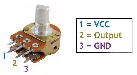
- Connection: Connect the potentiometer terminals 1 and 3 to VCC and GND or vice versa. Terminal 2 (wiper) to the MCU ADC pin.
Note: We can use any of the potentiometers with values between 1kΩ and 10kΩ.
Five LEDs Interfacing
Connect each PWM GPIO pin to an anode of a separate LED, and the cathode of each LED to GND with a current-limiting resistor in series to protect LEDs and GPIO pins.
Calculating the current-limited Resistor Value
Case 1: 5V Supply
- LED forward voltage (Vf) = 1.8V (from datasheet)
- Voltage across resistor (VR) = Supply voltage – Vf = 5V – 1.8V = 3.2V
- Resistor value (R) = VR / I = 3.2V / 10 mA = 320 Ω
Standard resistor values near 320 Ω: 330 Ω or 300 Ω (whichever is available).
Similarly, Case 2: 3.3V Supply
- Voltage across resistor (VR) = 3.3V – 1.8V = 1.5V
- Resistor value (R) = 1.5V / 10 mA = 150 Ω
Standard resistor value: 150 Ω.
So, by selecting a proper resistor, LED, and potentiometer connections, we can implement the task.
Below are the solutions to the given task using different microcontrollers
- STM32
- ESP32
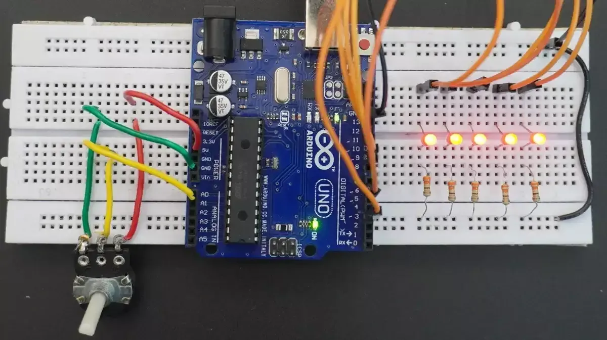
- Arduino UNO
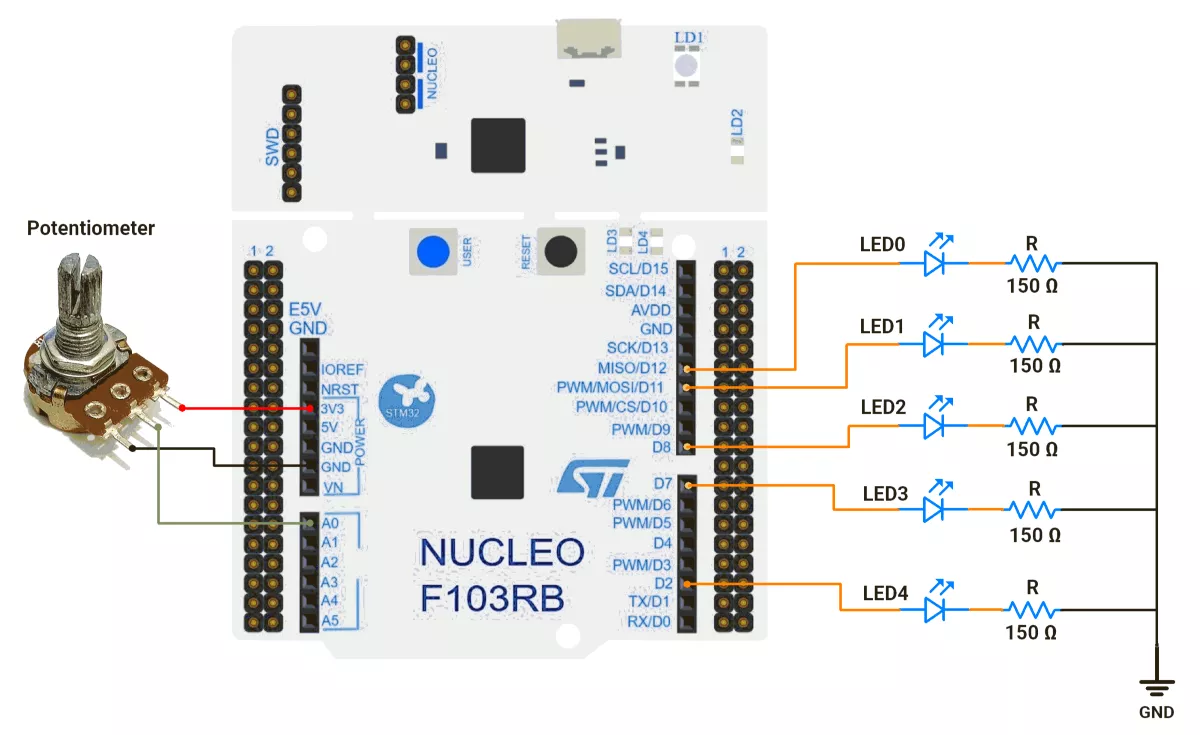
We’re using an STM32 NUCLEO-F103RB board, which runs at a 3.3V logic level.
Key Peripherals Used
- ADC1 Channel 0 (PA0): Reads the analog voltage from the potentiometer.
- TIM1 for PWM on channels 1, 2, and 3 (PA8, PA9, PA10).
- TIM3 for PWM on channels 1 and 2 (PA6, PA7).
- GPIO: PA8, PA9, PA10, PA6, and PA7 are configured as alternate function pins for PWM output.
- Optional USART2: Used for serial debugging (configured but not used here).
STM32 Hardware Connection
- Potentiometer Setup:
- Connect the potentiometer’s middle pin to PA0 (ADC1_IN0) for analog input.
- Connect the other two pins to 3.3V (VCC) and GND to create a voltage divider.
- Use a 10kΩ potentiometer for best results.
- LED Setup:
- PWM Output Pin: PA8 (TIM1 Channel 1).
- Connect the LED anode (long leg) to PA8.
- Connect the LED cathode (short leg) to GND through a 150Ω resistor.
- Repeat similar connections for PA9, PA10, PA6, and PA7.
Circuit Diagram
STM32 Firmware Implementation
Project Setup in STM32CubeIDE:
- Create a Project
- Open STM32CubeIDE, start a new project, and select the NUCLEO-F103RB board.
- Basic Configuration (via CubeMX inside CubeIDE)
- Clock: Use the default HSI oscillator with PLL enabled (configured in
SystemClock_Config). - GPIO:
- GPIO clocks enabled for PORTA, PORTB, PORTC, PORTD.
- GPIO pins for ADC input (PA0) and PWM output pins are auto-configured via CubeMX.
- ADC1 (Analog Input Source):
- Resolution: 12-bit (0–4095 range).
- Conversion mode: Single, software-triggered.
- Channel: ADC_CHANNEL_0 (PA0).
- Timer 1 (TIM1 – PWM Generator):
- Prescaler = 0 → Timer clock = APB2.
- Period (ARR) = 255
- PWM Mode 1 enabled on Channels 1, 2, and 3.
- Timer 3 (TIM3 – PWM Generator):
- Prescaler = 0.
- Period (ARR) = 255.
- PWM Mode 1 enabled on Channels 1 and 2.
- USART2: Enabled at 115200 baud, 8-N-1, for debugging/expansion if needed.
- Code Generation
- CubeMX will automatically generate all the startup code, including:
HAL_Init()→ Initializes the HAL library.SystemClock_Config()→ Configures HSI + PLL system clock.MX_GPIO_Init()→ Initializes all GPIO ports.MX_ADC1_Init()→ Configures ADC1 for analog input.MX_TIM1_Init()→ Configures TIM1 for PWM output.MX_TIM3_Init()→ Configures TIM3 for PWM output.MX_USART2_UART_Init()→ Initializes UART2 for debugging.
- This code sets up the hardware and prepares the project for firmware development, so we only need to add our application logic in the user code sections
- CubeMX will automatically generate all the startup code, including:
- Clock: Use the default HSI oscillator with PLL enabled (configured in
Code Snippets from main.c
ADC Initialization (MX_ADC1_Init):
hadc1.Instance = ADC1;
hadc1.Init.ScanConvMode = ADC_SCAN_DISABLE;
hadc1.Init.ContinuousConvMode = DISABLE;
hadc1.Init.DataAlign = ADC_DATAALIGN_RIGHT;
This configures ADC1 for single-channel operation with right-aligned 12-bit results.
Timer Initialization (MX_TIM1_Init and MX_TIM3_Init):
htim1.Init.Period = 255;  // ARR register value
htim1.Init.Prescaler = 0;  // No prescaling
sConfigOC.OCMode = TIM_OCMODE_PWM1;  // PWM Mode 1

//Similar configuration is applied for TIM3 as well.
These functions configure timers for PWM generation.
Macros Definition:
The provided code defines timer handles and channel mappings for cleaner code organization:
#define LED0_TIM_HANDLE        &htim3
#define LED0_TIM_CHANNEL       TIM_CHANNEL_1
// Additional LED mappings...

// ADC value range
#define ADC_MIN_VALUE          0
#define ADC_MAX_VALUE          4095

// PWM duty cycle range
#define PWM_MIN_VALUE          0
#define PWM_MAX_VALUE          255

Custom Mapping Function:
The mapValue() function provides linear interpolation between ranges:
uint16_t mapValue(uint16_t x, uint16_t inMin, uint16_t inMax,
                  uint16_t outMin, uint16_t outMax) {
    return (x - inMin) * (outMax - outMin) / (inMax - inMin) + outMin;
}
PWM Initialization in main():
Before the while loop, PWM channels are enabled:
HAL_TIM_PWM_Start(LED0_TIM_HANDLE, LED0_TIM_CHANNEL);
HAL_TIM_PWM_Start(LED1_TIM_HANDLE, LED1_TIM_CHANNEL);
// Start remaining PWM channels…
Main Control Loop:
The infinite loop continuously reads the ADC and updates LED brightness:
while (1) {
  // Start ADC conversion and wait for the result
  HAL_ADC_Start(&hadc1);
  HAL_ADC_PollForConversion(&hadc1, 20);
  adcValue = HAL_ADC_GetValue(&hadc1);

  // Map the potentiometer value to brightness levels for each LED
  uint16_t brightnessLed0 = mapValue(adcValue, ADC_MIN_VALUE, ADC_MAX_VALUE,
                                     PWM_MIN_VALUE, PWM_MAX_VALUE);
  uint16_t brightnessLed1 = mapValue(adcValue, ADC_MIN_VALUE, ADC_MAX_VALUE, 10, 130);
  uint16_t brightnessLed3 = mapValue(adcValue, ADC_MIN_VALUE, ADC_MAX_VALUE, 130, 10);
  uint16_t brightnessLed4 = mapValue(adcValue, ADC_MIN_VALUE, ADC_MAX_VALUE,
                                     PWM_MAX_VALUE, PWM_MIN_VALUE);
  uint16_t brightnessLed2;  // LED 2: Dynamic range with midpoint behavior

  // Calculate brightness for the middle LED (LED 2)
  if (adcValue < (ADC_MAX_VALUE / 2) + 1) {
    // If the potentiometer is below the midpoint, brightness increases
    brightnessLed2 = mapValue(adcValue, ADC_MIN_VALUE, ADC_MAX_VALUE / 2, 40, 60);
  } else {
    // If the potentiometer is above the midpoint, brightness decreases
    brightnessLed2 = mapValue(adcValue, (ADC_MAX_VALUE / 2) + 1,
                              ADC_MAX_VALUE, 60, 40);
  }

  // Apply calculated brightness to each LED
  __HAL_TIM_SET_COMPARE(LED0_TIM_HANDLE, LED0_TIM_CHANNEL, brightnessLed0);
  __HAL_TIM_SET_COMPARE(LED1_TIM_HANDLE, LED1_TIM_CHANNEL, brightnessLed1);
  __HAL_TIM_SET_COMPARE(LED2_TIM_HANDLE, LED2_TIM_CHANNEL, brightnessLed2);
  __HAL_TIM_SET_COMPARE(LED3_TIM_HANDLE, LED3_TIM_CHANNEL, brightnessLed3);
  __HAL_TIM_SET_COMPARE(LED4_TIM_HANDLE, LED4_TIM_CHANNEL, brightnessLed4);

  HAL_Delay(1);  // Short delay for smooth transitions
}
LED Control Logic Explanation:
- The STM32 reads the potentiometer position as a digital value (0 to 4095) via ADC.
- This value is mathematically mapped to PWM duty cycles (0 to 255) to control LED brightness.
- LEDs at opposite ends brighten and dim inversely—one side’s LEDs get brighter while the other side’s get dimmer.
- The center LED reaches peak brightness when the potentiometer is near the middle.
- The mapping and PWM updates happen continuously in a loop, creating a smooth, real-time seesaw brightness effect across all five LEDs.
Download Project
The complete STM32CubeIDE project (including .ioc configuration, main.c, and HAL files) is available here:
We are using the ESP32 DevKit v4 development board and programming it using the Arduino IDE.
- Before uploading, make sure to select “ESP32 Dev Module” as the board to ensure correct settings and compatibility.
PWM Options on ESP32
- analogWrite()
- LEDC Peripheral
- MCPWM Peripheral
- Sigma-Delta Modulator
- RMT Peripheral
- General-Purpose Timers
Among these, the LEDC (LED Controller) peripheral is a dedicated hardware PWM controller, optimized for applications like LED brightness control, and we will use it in this task.
Pins to Avoid for PWM on ESP32
- GPIO6–11 → Used for flash memory
- GPIO34–39 → Input-only pins (not suitable for PWM output)
- GPIO0, GPIO2, GPIO15 → Strapping pins (affect boot mode)
- EN, SENSOR_VP, SENSOR_VN → Reserved for special functions
Important Note
In Arduino Core v2.x or below for ESP32, LEDC API functions like ledcSetup() and ledcAttachPin() are used for PWM configuration.
In Arduino Core v3.x, these functions are removed to avoid compilation errors; use the updated LEDC API instead; otherwise, you will encounter a compilation error. e.g.:
ledcAttach(pin, freq, resolution);ledcWrite(channel, dutyCycle);
Reference: ESP32 Arduino Core 2.x → 3.0 Migration Guide
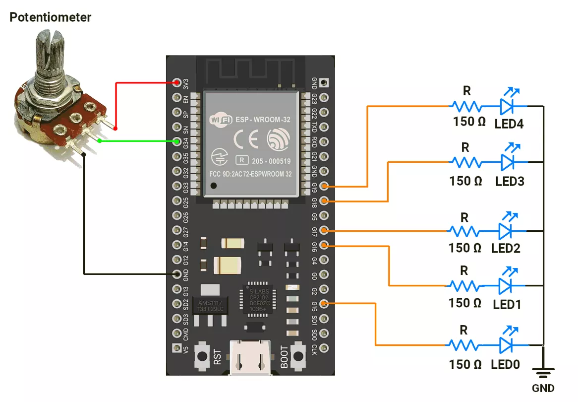
ESP32 Circuit Connection
- Connect the LEDs to GPIO pins 15, 16, 17, 18, and 19 with a 150 Ω resistor.
- Connect the potentiometer to the GPIO pin 34.
Circuit Diagram
ESP32 Firmware Implementation
Mapping ADC to PWM:
The ESP32’s 12-bit ADC converts the potentiometer’s position into digital values ranging from 0 (minimum) to 4095 (maximum).
To control the LED brightness using PWM (which ranges from 0 to 4095) in the given code, the ADC values are converted to a PWM value using the map() function.
Mapping value linearly for PWM:
- LED0: Brightness (PWM Value) increases from 0 to 4095 linearly with ADC values 0 to 4095.
- LED1: Brightness (PWM Value) increases from 1024 to 3071 linearly with ADC values 0 to 4095.
- LED2: Brightness (PWM Value) remains constant at 2048 (50%).
- LED3: Brightness (PWM Value) decreases from 3071 to 1024 linearly with ADC values 0 to 4095.
- LED4: Brightness (PWM Value) decreases from 4095 to 0 linearly with ADC values 0 to 4095.
Since LED brightness didn’t shift as expected with the above approach, we adjusted the mapping for smoother, more visible effects.
(Note: Brightness levels/ intensity behavior of LEDs vary based on specifications; different LEDs have different behaviors. The LEDs we used have similar brightness levels visible for PWM values in the upper range (e.g.,> 3500 PWM value)
Mapping value more dynamically to adjust for Better Visibility:
- LED0 → Follows the potentiometer directly: brightness increases smoothly from 0% to 100%.
- LED1 → Gradually brightens from about 4% to 90% duty cycle as the potentiometer increases.
- LED2 → brightness rises from ~12% to 80% at the midpoint, then decreases back down to ~12% as the potentiometer reaches maximum.
- LED3 → Opposite of LED1: starts bright (90%) and dims smoothly down to 4%.
- LED4 → Inverse of LED0: starts fully bright and fades to OFF.
Below is the code with both mapping (linear and dynamic).
Code with Linear Mapping
#define POT_PIN 34
const uint8_t led_pins[] = { 15, 16, 17, 18, 19 };  // PWM-capable pins for LEDs

void setup() {
  // Attach LEDs to PWM channels with 1 kHz frequency and 12-bit resolution (0–4095)
  for (uint8_t i = 0; i < 5; i++) {
    ledcAttach(led_pins[i], 1000, 12);  // pin, freq, resolution
    ledcWrite(led_pins[i], 0);          // Start with LEDs OFF
  }

  analogReadResolution(12);  // Set ADC to 12-bit (range: 0–4095)
}

void loop() {
  // Read the potentiometer value (0–4095) from Pin 34
  uint16_t potValue = analogRead(POT_PIN);

  // Update LED brightness levels based on potentiometer value
  setLEDBrightness(potValue);
}

// Function to calculate and set LED brightness levels from potentiometer input
void setLEDBrightness(uint16_t potValue) {
  /**
   * Brightness mapping (0–4095 duty cycle):
   * - LED0: Directly follows potentiometer (0 → 100% brightness)
   * - LED1: Increases gradually (25% → 75% brightness)
   * - LED2: Fixed at 50% brightness
   * - LED3: Decreases gradually (75% → 25% brightness, inverse of LED1)
   * - LED4: Inverse of LED0 (100% → 0% brightness)
   */
  uint16_t brightnessLed0 = potValue;
  uint16_t brightnessLed1 = map(potValue, 0, 4095, 1024, 3071);
  uint16_t brightnessLed2 = 2048;
  uint16_t brightnessLed3 = map(potValue, 0, 4095, 3071, 1024);
  uint16_t brightnessLed4 = 4095 - potValue;

  // Apply calculated brightness values to LEDs
  ledcWrite(led_pins[0], brightnessLed0);
  ledcWrite(led_pins[1], brightnessLed1);
  ledcWrite(led_pins[2], brightnessLed2);
  ledcWrite(led_pins[3], brightnessLed3);
  ledcWrite(led_pins[4], brightnessLed4);

  delay(1);  // Short delay for smoother LED transitions
}
Code with more Dynamic mapping for proper visibility
#define POT_PIN 34
#define ADC_RESOLUTION 12
#define PWM_RESOLUTION 12
#define ADC_MAX_VALUE 4095
#define PWM_MAX_VALUE 4095

const int led_pins[] = { 15, 16, 17, 18, 19 };  // PWM-capable LED pins
uint16_t potValue = 0;

void setup() {
  for (uint8_t i = 0; i < 5; i++) {
    // Attach PWM to pin with 1kHz frequency and 12-bit resolution
    ledcAttach(led_pins[i], 1000, PWM_RESOLUTION);
    ledcWrite(led_pins[i], 0);  // Start OFF
  }

  analogReadResolution(ADC_RESOLUTION);  // Set ADC to 12-bit (0–4095)
  Serial.begin(115200);
}

void loop() {
  potValue = analogRead(POT_PIN);  // Read potentiometer value
  setLEDBrightness(potValue);      // Update LED brightness levels
  delay(10);                       // Small delay for smooth transitions
}

void setLEDBrightness(int potValue) {
  uint16_t brightnessLed0 = potValue;  // LED0 directly follows potentiometer value (0–100%)

  // LED1 brightness increases gradually from 4% → 90% as potValue goes 0 → 4095
  uint16_t brightnessLed1 = map(potValue, 0, ADC_MAX_VALUE, PWM_MAX_VALUE * 0.04, PWM_MAX_VALUE * 0.90);

  // LED3 brightness decreases gradually from 90% → 4% as potValue goes 0 → 4095
  uint16_t brightnessLed3 = map(potValue, 0, ADC_MAX_VALUE, PWM_MAX_VALUE * 0.90, PWM_MAX_VALUE * 0.04);

  uint16_t brightnessLed4 = ADC_MAX_VALUE - potValue;  // LED4 inversely follows potentiometer value

  uint16_t brightnessLed2;
  if (potValue <= (ADC_MAX_VALUE / 2)) {
    // LED2 increases between 12% → 80% brightness for first half of pot range
    brightnessLed2 = map(potValue, 0, ADC_MAX_VALUE / 2, PWM_MAX_VALUE * 0.12, PWM_MAX_VALUE * 0.80);
  } else {
    // LED2 decreases back from 80% → 12% brightness for second half of pot range
    brightnessLed2 = map(potValue, ADC_MAX_VALUE / 2, ADC_MAX_VALUE, PWM_MAX_VALUE * 0.80, PWM_MAX_VALUE * 0.12);
  }

  // Debug output (uncomment if needed for testing)
  // Serial.printf("%u %u %u %u %u\n", brightnessLed0, brightnessLed1, brightnessLed2, brightnessLed3, brightnessLed4);

  // Write brightness values to LEDs
  ledcWrite(led_pins[0], brightnessLed0);
  ledcWrite(led_pins[1], brightnessLed1);
  ledcWrite(led_pins[2], brightnessLed2);
  ledcWrite(led_pins[3], brightnessLed3);
  ledcWrite(led_pins[4], brightnessLed4);
}
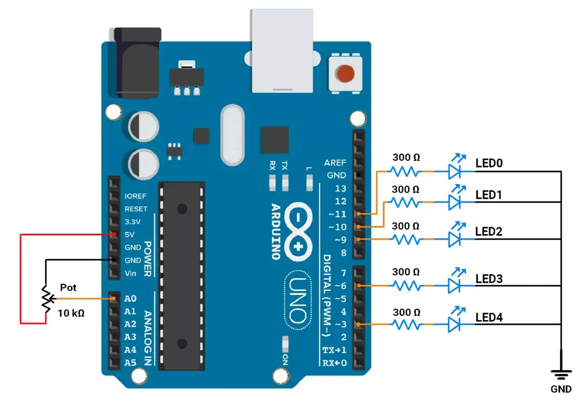
We are using the Arduino UNO development board and programming it using the Arduino IDE.
- Before uploading, make sure to select “Arduino UNO” as the board to ensure correct settings and compatibility.
The LEDs are connected to an Arduino UNO
In Arduino UNO, the PWM signal is generated using the analogWrite().
It has 6 PWM pins (3, 5, 6, 9, 10, 11) with 8-bit resolution (0–255) and fixed frequencies of ~490 Hz or ~976 Hz.
Circuit connection
Let's connect,
- LED to GPIO pins 3,6,9,10, and 11 with 330Ω resistor.
- Potentiometer to GPIO pin A0.
Circuit Diagram
Firmware
After analyzing the task requirement, as shown in the GIF.
Mapping ADC to PWM:
The ADC provides values ranging from 0 to 1023.
To control the LED brightness using PWM (which ranges from 0 to 255), the ADC values are converted to PWM values using the map() function.
Mapping value linearly for PWM:
- LED0: Brightness (PWM Value) increases from 0 to 255 linearly with ADC values 0 to 1023.
- LED1: Brightness (PWM Value) increases from 64 to 191 linearly with ADC values 0 to 1023.
- LED2: Brightness (PWM Value) remains constant at 127 (50%).
- LED3: Brightness (PWM Value) decreases from 191 to 64 linearly with ADC values 0 to 1023.
- LED4: Brightness (PWM Value) decreases from 255 to 0 linearly with ADC values 0 to 1023.
Since LED brightness didn’t shift as expected with the above approach, we adjusted the mapping for smoother, more visible effects.
(Note: Brightness levels/ intensity behavior of LEDs vary based on specifications; different LEDs have different behaviors. The LEDs we are using have similar brightness levels visible for PWM values in the upper range (e.g., 150 to 255)
Mapping value more dynamically to adjust for Better Visibility:
- LED0: Brightness (PWM Value) increases from 0 to 255 linearly with ADC values 0 to 1023.
- LED1: Brightness (PWM Value) increases from 10 to 245 linearly with ADC values 0 to 1023.
- LED2: Brightness (PWM Value)
- Increases from 30 to 225 as ADC value goes from 0 to 511.
- Decreases from 225 to 30 as the ADC value goes from 512 to 1023.
- LED3: Brightness (PWM Value) decreases from 245 to 10 linearly with ADC values 0 to 1023.
- LED4: Brightness (PWM Value) decreases from 255 to 0 linearly with ADC values 0 to 1023.
Code with Linear Mapping
const int ledPins[] = { 11, 10, 9, 6, 3 };  // PWM pins for LEDs

// Variable to store potentiometer value
int potValue = 0;

void setup() {
  // Initialize all LED pins as outputs
  for (int i = 0; i < 5; i++) {
    pinMode(ledPins[i], OUTPUT);
  }
}

void loop() {
  // Read the potentiometer value (range: 0–1023) connected to Pin A0
  potValue = analogRead(A0);

  // Adjust the brightness of LEDs based on the potentiometer value
  setLEDBrightness(potValue);
}

// Function to calculate and set LED brightness levels based on potentiometer input
void setLEDBrightness(int potValue) {
  // Map the potentiometer value (0–1023) to PWM brightness range (0–255)
  // Brightness levels are adjusted to create a gradient effect across LEDs
  int brightnessLed0 = map(potValue, 0, 1023, 0, 255);   // LED 0: 0% to 100% brightness
  int brightnessLed1 = map(potValue, 0, 1023, 64, 191);  // LED 1: Mid-range brightness
  int brightnessLed2 = 127;                              // LED 2: Fixed 50% brightness
  int brightnessLed3 = map(potValue, 0, 1023, 191, 64);  // LED 3: Inverse mid-range brightness
  int brightnessLed4 = map(potValue, 0, 1023, 255, 0);   // LED 4: 100% to 0% brightness

  /**
   * When the potentiometer is at 100% position, the ADC value fluctuates between 1023 and 1022.
   * This causes the PWM value to alternate between 255 and 254, leading to noticeable LED flickering.
   * To eliminate the flickering, any brightness value below 2 is set to 0,
   * ensuring the LED turns off completely in such cases.
   */
  if (brightnessLed4 < 2) {
    brightnessLed4 = 0;
  }

  // Set PWM values for each LED
  analogWrite(ledPins[0], brightnessLed0);  // Adjust brightness for LED 0
  analogWrite(ledPins[1], brightnessLed1);  // Adjust brightness for LED 1
  analogWrite(ledPins[2], brightnessLed2);  // Fixed brightness for LED 2
  analogWrite(ledPins[3], brightnessLed3);  // Adjust brightness for LED 3
  analogWrite(ledPins[4], brightnessLed4);  // Adjust brightness for LED 4

  // Short delay for smooth transitions
  delay(10);
}
Code with more Dynamic mapping for proper visibility
// Define the PWM pins for the LEDs
const int ledPins[] = { 11, 10, 9, 6, 3 };  // Array of LED pins (PWM-enabled pins)

// Variable to store the potentiometer reading
int potValue = 0;

void setup() {
  // Configure each LED pin as an output
  for (int i = 0; i < 5; i++) {
    pinMode(ledPins[i], OUTPUT);
  }
}

void loop() {
  // Read the analog input from the potentiometer connected to pin A0 (range: 0–1023)
  potValue = analogRead(A0);

  // Set the brightness levels of LEDs based on the potentiometer value
  setLEDBrightness(potValue);

  // Short delay for smoother brightness transitions
  delay(10);
}

/**
 * Function to calculate and set the brightness levels of LEDs
 * based on the potentiometer input.
 * @param potValue - Potentiometer ADC reading (0–1023)
 */
void setLEDBrightness(int potValue) {
  // Map the potentiometer value to brightness levels for each LED
  int brightnessLed0 = map(potValue, 0, 1023, 0, 255);   // LED 0: Brightness increases from 0 to 255
  int brightnessLed1 = map(potValue, 0, 1023, 10, 245);  // LED 1: Limited brightness range (10–245)
  int brightnessLed3 = map(potValue, 0, 1023, 245, 10);  // LED 3: Reverse brightness (245–10)
  int brightnessLed4 = map(potValue, 0, 1023, 255, 0);   // LED 4: Brightness decreases from 255 to 0
  int brightnessLed2;                                    // LED 2: Dynamic range with midpoint behavior

  /**
   * When the potentiometer is at 100% position, the ADC value fluctuates between 1023 and 1022.
   * This causes the PWM value to alternate between 255 and 254, leading to noticeable LED flickering.
   * To eliminate the flickering, any brightness value below 2 is set to 0,
   * ensuring the LED turns off completely in such cases.
   */
  if (brightnessLed4 < 2) {
    brightnessLed4 = 0;
  }

  // Calculate brightness for the middle LED (LED 2)
  if (potValue < 512) {
    // If potentiometer is below the midpoint, brightness increases (30–225)
    brightnessLed2 = map(potValue, 0, 511, 30, 225);
  } else {
    // If potentiometer is above the midpoint, brightness decreases (225–30)
    brightnessLed2 = map(potValue, 512, 1023, 225, 30);
  }

  // Apply calculated brightness to each LED
  analogWrite(ledPins[0], brightnessLed0);  // Set brightness for LED 0
  analogWrite(ledPins[1], brightnessLed1);  // Set brightness for LED 1
  analogWrite(ledPins[2], brightnessLed2);  // Set brightness for LED 2
  analogWrite(ledPins[3], brightnessLed3);  // Set brightness for LED 3
  analogWrite(ledPins[4], brightnessLed4);  // Set brightness for LED 4

  // Short delay for smooth transitions
  delay(10);
}
Code Explanation
Brightness for LEDs:
- LED 0: Linear increase from 0 to 255.
- LED 1: Limited range increase from 10 to 245.
- LED 2: Dynamic increase from 30 to 225 (0–511) and decrease from 225 to 30 (512–1023).
- LED 3: Reverse of LED 1, decreases from 245 to 10.
- LED 4: Linear decrease from 255 to 0.
- In the next cycle, the above conditions will be reversed.
Map Function:
- The map() function has a limitation: it works only with integer numbers.
- For example, if the expected mapped value is 1.999, the function will return 1 instead of a precise decimal value.
- When the potentiometer is set to 100%, the ADC value fluctuates between 1022 and 1023.
- This fluctuation causes the PWM value to vary between 0 and 1, which leads to noticeable LED flickering.
- To resolve this issue:
- Add a condition to check the PWM value.
- If the PWM value is below 2, set it to 0.
- This arrangement ensures smooth and stable LED operation, preventing flickering.
Output