79. Simultaneous Square Wave Generation
The Square Wave Generation Challenge
- Generating a high-frequency square wave is simple.
- Generating two different high-frequency square waves simultaneously without CPU load is harder.
- Software-based toggling fails at hundreds of kHz due to:
- CPU execution jitter
- Interrupt latency
- Main loop blocking
The Robust Approach
Use two independent hardware timers configured in Output Compare or PWM mode so that:
- Each timer runs autonomously
- Each toggles its assigned output pin directly in hardware
- No CPU intervention is needed for timing
Understanding the Key Timer Parameter
Different microcontrollers use different names for the same concept:
- STM32: Auto-Reload Register (ARR)
- AVR: Output Compare Register (OCRnA/B)
- PIC: Period Register (PRx)
- NXP/Freescale: MOD register
Generic term: Timer Period Register or Maximum Count Value – the value at which the timer counter resets back to zero.
Operation:
- Timer counts from 0 to the Maximum Count Value.
- When it reaches this value:
- It resets to 0
- Optionally toggles the output pin if in toggle mode
- Smaller value → faster counting → higher output frequency.
Frequency Calculation (Prescaler = 0)
Timer Frequency:
Timer_Freq = Timer_Clock / (Max_Count_Value + 1)
Output Frequency in Toggle Mode:
Output_Freq = Timer_Freq / 2(Reason: Two toggles make one full waveform cycle)
Why Two Timers Instead of One?
- All channels in a single timer share the same Maximum Count Value → same base frequency
- You can only adjust the duty cycle per channel, not the base frequency.
- Simulating different base frequencies via interrupts would require servicing every 1–2 µs at these frequencies — impractical when the CPU is busy.
Calculation Example
Given:
- Timer clock = 64 MHz
- Prescaler = 0
- Output mode = Toggle
Formula:
Max_Count_Value = (Timer_Clock / (2 × Desired_Freq)) − 1
For 307 kHz:
Max_Count_Value = (64,000,000 / (2 × 307,000)) − 1 ≈ 103
For 570 kHz:
Max_Count_Value = (64,000,000 / (2 × 570,000)) − 1 ≈ 55
Final Configuration
- Timer A → Max Count = 103 → 307 kHz output
- Timer B → Max Count = 55 → 570 kHz output
Both timers run independently and continuously, generating precise square waves without affecting the main loop’s performance.
So, by considering the above points, we can implement the task.
Below are the solutions to the given task using different microcontrollers
- STM32
- ESP32
- Arduino UNO
We’re using an STM32 NUCLEO-F103RB board.
We have to generate two square waves with different frequencies(307 kHz and 570 kHz).
We will use two different hardware timers available to use in output compare toggle mode.
Key Peripherals Used:
- TIM1 → Output Compare Channel 1 → 307 kHz
- TIM2 → Output Compare Channel 1 → 570 kHz
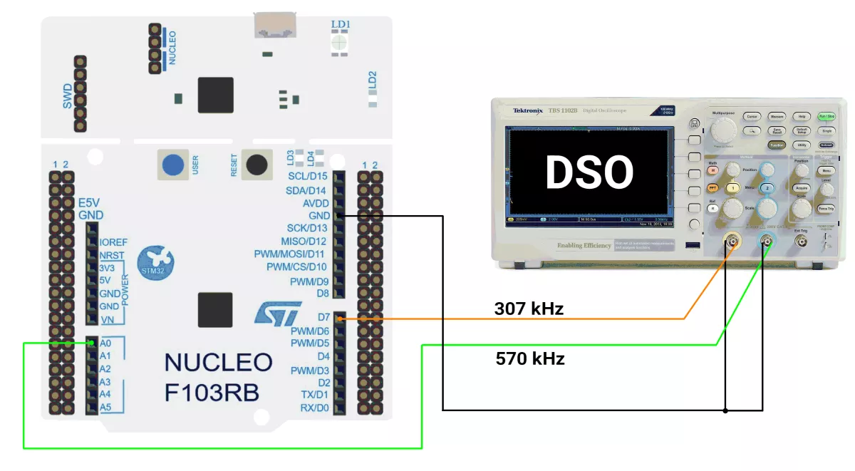
STM32 Hardware Connection
- Connect TIM1_CH1 (D7) to Channel 1 of DSO.
- Connect TIM2_CH1 (A0) to Channel 2 of DSO.
- Share a common GND
- Connect the STM32 NUCLEO-F103RB board to the PC via USB cable for Power.
Circuit Diagram:
STM32 Firmware Implementation
Project Setup in STM32CubeIDE
- Create a Project
- Open STM32CubeIDE and start a new project, select the NUCLEO-F103RB board.
- Basic Configuration (via CubeMX inside CubeIDE)
- Clock:
- Go to the Clock Configuration tab.
- Confirm APB1 Timer Clock is 64 MHz.
- If APB1 prescaler > 1, STM32F1 timers automatically get doubled clock (e.g., APB1 = 32 MHz → timer = 64 MHz).
- This is important because Prescaler values depend on the timer clock.
- Enable TIM1 and TIM2
- Clock:
- Go to Pinout & Configuration view.
- Under Timers:
- Enable TIM1 → Mode: Output Compare CH1
- Enable TIM2 → Mode: Output Compare CH1
- Configure TIM1 (307 KHz)
- Click TIM1 in the left panel.
- Under Parameter Settings:
- Prescaler =
0 - Counter Mode = Up
- Counter Period (ARR) =
103 - Clock Division = Div1
- Auto-Reload Preload = Disable (for fixed timing)
- Prescaler =
- Configure TIM2 (570 kHz)
- Click TIM2 in the left panel.
- Under Parameter Settings:
- Prescaler =
0 - Counter Mode = Up
- Counter Period (ARR) =
55 - Clock Division = Div1
- Auto-Reload Preload = Disable
- Prescaler =
- Code Generation
- CubeMX will automatically generate all the startup code, including:
HAL_Init()– Initializes the HAL library.SystemClock_Config()– Configures the system clock.MX_USART2_UART_Init()→ Sets up USART2.MX_GPIO_Init()– Configures GPIO clocks.MX_TIM1_Init()– Sets up TIM1.MX_TIM2_Init()– Sets up TIM2.
- This code sets up the hardware and prepares the project for firmware development, so we only need to add our application logic in the user code sections
- CubeMX will automatically generate all the startup code, including:
Code Snippets from main.c
TIM1 Initialization – Square Wave Generation
htim1.Instance = TIM1;
htim1.Init.Prescaler = 0;                  // No division, full 64 MHz input
htim1.Init.Period = 103;                   // Auto-reload for target frequency
sConfigOC.OCMode = TIM_OCMODE_TOGGLE;      // Toggle output on match
sConfigOC.Pulse = 0;                       // Match at counter = 0
HAL_TIM_OC_ConfigChannel(&htim1, &sConfigOC, TIM_CHANNEL_1);- Purpose: Generates a square wave on TIM1_CH1.
- Frequency formula:
Fout = fclk / (2×(PSC+1) × (ARR+1))
- For 64 MHz, ARR=103, PSC=0 →
Fout ≈ 64 MHz / (2×10⁴) ≈ 307.7 kHz
TIM2 Initialization – Square Wave Generation
htim2.Instance = TIM2;
htim2.Init.Prescaler = 0;                  // No division
htim2.Init.Period = 55;                    // Faster toggle than TIM1
sConfigOC.OCMode = TIM_OCMODE_TOGGLE;      // Toggle output
sConfigOC.Pulse = 0;
HAL_TIM_OC_ConfigChannel(&htim2, &sConfigOC, TIM_CHANNEL_1);- Purpose: Generates a second independent square wave on TIM2_CH1.
- For 64 MHz, ARR=55, PSC=0 →
Fout ≈ 64 MHz / (2×56) ≈ 571.4 kHz
Main loop logic
int main(void) {
  /* Reset of all peripherals, Initializes the Flash interface and the Systick. */
  HAL_Init();

/* Configure the system clock */
  SystemClock_Config();

 /* Initialize all configured peripherals */
  MX_GPIO_Init();
  MX_USART2_UART_Init();
  MX_TIM1_Init();
  MX_TIM2_Init();

  // Start in Output Compare mode
  HAL_TIM_OC_Start(&htim1, TIM_CHANNEL_1);  //PA8(D7)
  HAL_TIM_OC_Start(&htim2, TIM_CHANNEL_1);  //PA0(A0)

  while (1) {
  }
}
Flow of Operation
- Initialization Phase
- System clock and GPIO configured.
- TIM1 and TIM2 are initialized in Output Compare Toggle Mode.
- Execution Phase
- Both timers start outputting their respective square waves immediately after HAL_TIM_OC_Start().
- The CPU is free for other tasks — wave generation is hardware-driven.
Download Project
The complete STM32CubeIDE project (including .ioc configuration, main.c, and HAL files) is available here:
📥 Download Project
- We are using the ESP32 DevKit v4 development board and programming it using the Arduino IDE.
- Before uploading, make sure to select “ESP32 Dev Module” as the board to ensure correct settings and compatibility.
- The ESP32 has four general-purpose hardware timers, primarily designed for time-keeping and interrupt-driven tasks (e.g., delays, periodic events, scheduling), not optimized for high-frequency waveform generation.
- For precise square waves (PWM signal with 50% duty cycle), the ESP32 uses the dedicated peripheral LEDC (LED Controller) module with four independent PWM timers (0–3) and up to 16 channels, generating signals directly on GPIOs without CPU overhead.
- So in this task, we will use the LEDC timers to generate square waves.
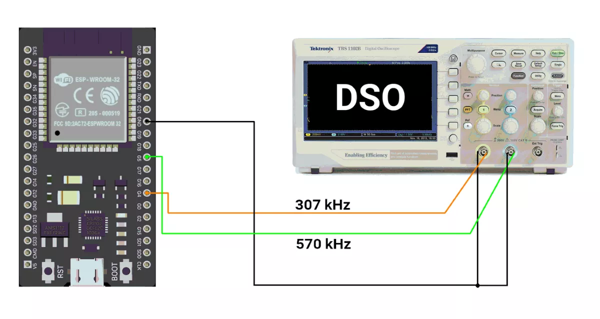
ESP32 Circuit Connection
- Connect PINs 4 and 5 to DSO channels 1 and 2.
ESP32 Firmware Implementation
The ESP32’s LEDC (LED Controller) hardware is used to generate signals. Normally, it’s for PWM, but with a 50% duty cycle, it produces a square wave.
Two square wave signals are created with an independent Timer for each:
- 307 kHz on GPIO 4 → Timer 0 is used.
- 570 kHz on GPIO 5 → Timer 1 is used.
ESP32 Code
#include "driver/ledc.h"   // Include ESP32 LEDC (PWM) driver
// Hardware configuration for square wave signal 307 kHz
#define SQW1_GPIO     4                  // GPIO pin for first square wave
#define SQW1_FREQ     307000              // Frequency for square wave 1 (~307 kHz)
#define SQW1_CHANNEL  LEDC_CHANNEL_0      // Use LEDC channel 0
#define SQW1_TIMER    LEDC_TIMER_0        // Use LEDC timer 0
#define SQW1_MODE     LEDC_HIGH_SPEED_MODE// High-speed mode
#define SQW1_RES      LEDC_TIMER_2_BIT    // Resolution = 2 bits

// Hardware configuration for square wave signal 570 kHz
#define SQW2_GPIO     5                 // GPIO pin for second square wave
#define SQW2_FREQ     570000              // Frequency for square wave 2 (~570 kHz)
#define SQW2_CHANNEL  LEDC_CHANNEL_1      // Use LEDC channel 1
#define SQW2_TIMER    LEDC_TIMER_1        // Use LEDC timer 1
#define SQW2_MODE     LEDC_HIGH_SPEED_MODE// High-speed mode
#define SQW2_RES      LEDC_TIMER_2_BIT    // Resolution = 2 bits

void setup() {
  // Configure Timer for Square Wave 1 (≈307 kHz)
  ledc_timer_config_t timer1 = {
    .speed_mode       = SQW1_MODE,
    .duty_resolution  = SQW1_RES,
    .timer_num        = SQW1_TIMER,
    .freq_hz          = SQW1_FREQ,
    .clk_cfg          = LEDC_AUTO_CLK
  };
  ledc_timer_config(&timer1);

  // Configure Channel for Square Wave 1
  ledc_channel_config_t channel1 = {
    .gpio_num       = SQW1_GPIO,
    .speed_mode     = SQW1_MODE,
    .channel        = SQW1_CHANNEL,
    .intr_type      = LEDC_INTR_DISABLE,
    .timer_sel      = SQW1_TIMER,
    .duty           = 2,   // 50% duty → square wave
    .hpoint         = 0
  };
  ledc_channel_config(&channel1);

  // Configure Timer for Square Wave 2 (≈570 kHz)
  ledc_timer_config_t timer2 = {
    .speed_mode       = SQW2_MODE,
    .duty_resolution  = SQW2_RES,
    .timer_num        = SQW2_TIMER,
    .freq_hz          = SQW2_FREQ,
    .clk_cfg          = LEDC_AUTO_CLK
  };
  ledc_timer_config(&timer2);

  // Configure Channel for Square Wave 2
  ledc_channel_config_t channel2 = {
    .gpio_num       = SQW2_GPIO,
    .speed_mode     = SQW2_MODE,
    .channel        = SQW2_CHANNEL,
    .intr_type      = LEDC_INTR_DISABLE,
    .timer_sel      = SQW2_TIMER,
    .duty           = 2,   // 50% duty → square wave
    .hpoint         = 0
  };
  ledc_channel_config(&channel2);

  // update frequency & duty for both channels
  ledc_set_freq(SQW1_MODE, SQW1_TIMER, SQW1_FREQ);
  ledc_set_duty(SQW1_MODE, SQW1_CHANNEL, 2);
  ledc_update_duty(SQW1_MODE, SQW1_CHANNEL);

  ledc_set_freq(SQW2_MODE, SQW2_TIMER, SQW2_FREQ);
  ledc_set_duty(SQW2_MODE, SQW2_CHANNEL, 2);
  ledc_update_duty(SQW2_MODE, SQW2_CHANNEL);
}

void loop() {
  // Nothing required here — square waves run entirely in hardware
}
Code Explanation
Let's understand the important function
ledc_timer_config(&timer_config)- Configures one LEDC timer.
- A timer defines:
- Frequency (
freq_hz) - Resolution (
duty_resolution) - Speed mode (
LEDC_HIGH_SPEED_MODE) - Which timer (
LEDC_TIMER_0,LEDC_TIMER_1, etc.)
- Frequency (
- Example:
ledc_timer_config(&timer1);→ Sets up Timer 0 to run at 307 kHz with 2-bit resolution.
ledc_channel_config(&channel_config)- Configures one LEDC channel.
- A channel links a GPIO pin to a timer.
- Defines:
- GPIO output pin (gpio_num)
- Which timer to use (timer_sel)
- Initial duty cycle (duty)
- Example:
ledc_channel_config(&channel1);→ Sends Timer 0’s square wave (307 kHz, 50%) out on GPIO 4.
ledc_set_freq(speed_mode, timer, freq)- Updates the frequency of a timer after it’s already running.
- Ensures the timer is locked to the required frequency.
- Example:
ledc_set_freq(SQW1_MODE, SQW1_TIMER, SQW1_FREQ);
ledc_set_duty(speed_mode, channel, duty)- Sets the duty cycle for a channel.
- With 2-bit resolution (0–3 duty steps):
- 0 = always LOW
- 3 = always HIGH
- 2 = ~50% duty → square wave
- Example:
ledc_set_duty(SQW1_MODE, SQW1_CHANNEL, 2);
ledc_update_duty(speed_mode, channel)- Applies the new duty cycle to hardware immediately.
- Must be called after
ledc_set_duty(). - Example:
ledc_update_duty(SQW1_MODE, SQW1_CHANNEL);
We are using the Arduino UNO development board and programming it using the Arduino IDE.
- Before uploading, make sure to select “Arduino UNO” as the board to ensure correct settings and compatibility.
Using tone() function
We can use the tone() function for the generation of square waves. However, it has some limitations
- tone() function generates frequency on only 1 pin at a time.
So we will use Timer1 and Timer2 for the toggling of pins (i.e., generating the frequency).
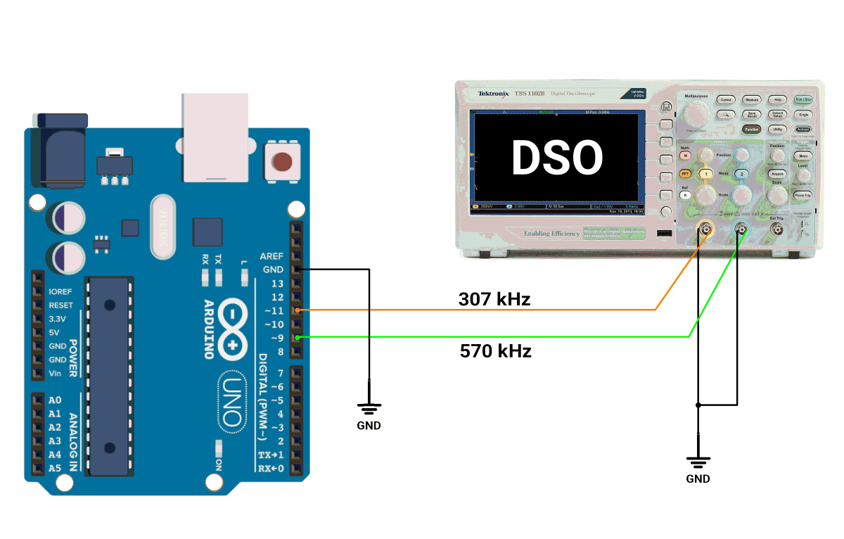
Arduino UNO Connection diagram
Arduino UNO Code
void setup() {
  cli();  // Disable interrupts during configuration

  // Timer2 configuration for ~307 kHz on D11 (OC2A)
  TCCR2A = (1 << WGM21) | (1 << COM2A0);  // CTC mode, toggle OC2A on match
  TCCR2B = (1 << CS20);                   // Prescaler = 1
  OCR2A = 25;                             // Compare match value for ~307 kHz

  // Timer1 configuration for ~570 kHz on D9 (OC1A)
  TCCR1A = (1 << COM1A0);               // Toggle OC1A on compare match
  TCCR1B = (1 << WGM12) | (1 << CS10);  // CTC mode, prescaler = 1
  OCR1A = 13;                           // Compare match value for ~570 kHz

  // Set pins as output
  pinMode(9, OUTPUT);
  pinMode(11, OUTPUT);

  sei();  // Enable interrupts
}

void loop() {
  while (true) {
    //In this loop, the Microcontroller monitors and performs important tasks constantly.
  }
}
Code Explanation:
- Timer2 Setup (Pin 11, 307 kHz)
- CTC Mode (
WGM21set): Timer2 resets when reached atOCR2Avalue. - Toggle Mode on
OC2A(COM2A0set): The pin automatically toggles. - Prescaler = 1 (
CS20set): Timer2 runs at full speed (16 MHz). OCR2A= 25: Generates 307 kHz.
- CTC Mode (
- Timer1 Setup (Pin 9, 570 kHz)
- CTC Mode (
WGM12set): Timer1 resets when it reaches at theOCR1Avalue. - Toggle Mode on
OC1A(COM1A0set): Pin toggles on compare match. - Prescaler = 1 (
CS10set): Runs at full 16 MHz. OCR1A= 13: Generates 570 kHz.
- CTC Mode (
- Interrupts and Efficiency
cli()disables interrupts to ensure configuration stability.sei()enables interrupts after configuration is complete.loop()function is needed as everything runs in hardware.
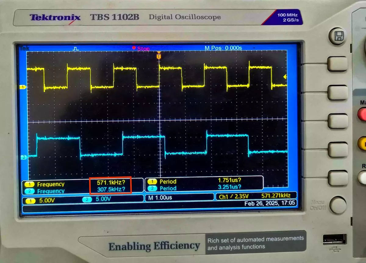
Output
Hardware setup
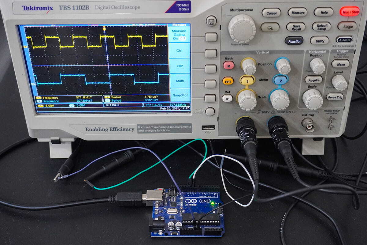
DSO output
Video