62. Single Double and Long Press with Interrupts
We have to detect single, double, and long-press events from the push button Control LED1 and LED2 based on the press events while the main loop is busy with other tasks.
To ensure instant response and non-blocking operation, we use interrupts.
- Single press: Toggle LED1
- Double-press: Toggle LED2
- Long press (over 1 second): Turn off both LED1 and LED2
Interrupts
- External Interrupt: Detects button press instantly.
- Timer Interrupt: Defines timing windows for press-type detection (single, double, long).
Detecting the Type of Button Press
To differentiate between single, double, and long presses, specific timing windows are used.
Timing Windows for button press detection are as follows
- 50 – 300 ms → Single press
- 50 – 300 ms + second press within 500 ms → Double press
- > 800 ms → Long press
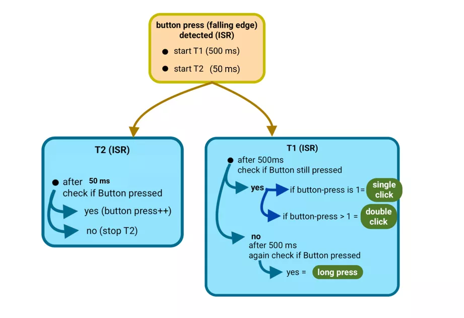
Approach
- Start a timer for 500 ms when the first press is detected.
- Monitor all presses within this 500 ms window.
After 500 ms (button released):
- 1 press → Single Click
- 2 or more presses → Double/Multiple Click
After 500 ms (button still held):
- Continue monitoring for another 500 ms.
- If the button remains pressed for a total of ~1 second, register as a Long Press.
Debouncing Logic
When a mechanical button is pressed, it often produces unwanted rapid ON/OFF transitions (bounces) due to contact vibration.
To ensure a clean and stable reading, debouncing logic introduces a short time delay before validating the press.
Process
- Detect button press → start debounce timer (typically 50 ms).
- After 50 ms, check if the button is still pressed.
- If yes → register it as a valid press and increment the count.
- If the signal fluctuates during this period, the timer resets and restarts the 50 ms delay.
Thus, a button press is confirmed only after a stable 50-ms signal is observed.
Hardware Setup
- Connect two LEDs with appropriate current-limiting resistors to limit the current to 10 mA.
- One push-button configured to provide clean HIGH/LOW levels (with pull-up or pull-down).
So, by selecting a proper resistor, LED, and push-button switch correctly, we can implement the task.
Below are the solutions to the given task using different microcontrollers
- STM32
- ESP32
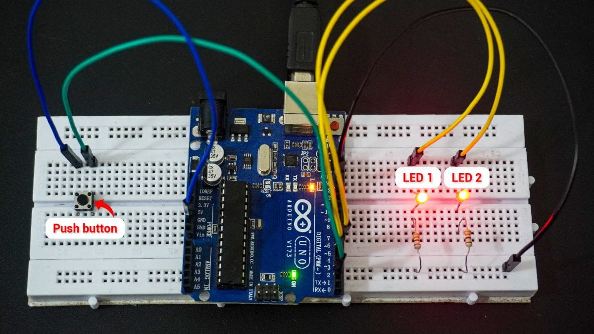
- Arduino UNO
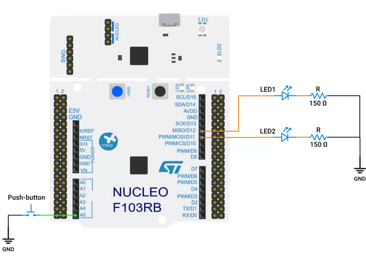
We’re using an STM32 NUCLEO-F103RB board, which runs at a 3.3V logic level.
Key Peripherals Used:
- GPIO & EXTI: Read a push-button on PC0 (active-LOW, internal pull-up) with interrupts on both edges; drive two LEDs on PA6 and PA7.
- TIM2 (one-shot): Debounce window (50 ms).
- TIM3 (one-shot): Double-click classification window (500 ms).
- USART2 (optional): 115200 baud for debug prints
Hardware Connection
- Switch (active-LOW):
Connect one terminal of the push-button to PC0 (A5) and the other terminal to GND. In software, enable the internal pull-up so the line is normally HIGH and goes LOW when pressed. - LEDs: Connect one terminal of the LEDs to GPIO pins PA6 (LED1) and PA7 (LED2), and the other terminal to GND through current-limiting resistors of 150 ohms.
Circuit Diagram
- PC0 —[button to GND], PULL-UP → EXTI0
- PA6 → LED1 (push-pull output)
- PA7 → LED2 (push-pull output)
Firmware Implementation
Project Setup in STM32CubeIDE:
- Create a Project
- Open STM32CubeIDE and start a new project, select the NUCLEO-F103RB board.
- Basic Configuration (via CubeMX inside CubeIDE)
- Clock: Use default HSI + PLL (SystemClock_Config provided by Cube, typical SYSCLK ≈ 64 MHz).
- GPIO Configuration:
- PC0 as GPIO_EXTI on both Rising and Falling edges, Pull-Up enabled.
- PA6, PA7 as GPIO_Output Push-Pull, Low speed, No pull.
- NVIC: Enable EXTI line 0 interrupt.
- NVIC:
- EXTI0_IRQn enabled (priority e.g. 0).
- TIM2_IRQn (priority e.g. 1).
- TIM3_IRQn (priority e.g. 2).
- TIM2 –
- Mode: Internal Clock
- Prescaler = 64000 − 1
- Counter Mode = Up
- Period (ARR) = 50 − 1
- Auto-reload preload = Disable
- Enable Update Interrupt (TIM2 global interrupt in NVIC)
- Why these values?
Timer clock = 64 MHz → tick = (PSC+1)/f = 64000/64 MHz = 1 ms.
Period 50 → 50 ms interrupt.
- TIM3 –
- Mode: Internal Clock
- Prescaler = 64000 − 1
- Counter Mode = Up
- Period (ARR) = 500 − 1
- Auto-reload preload = Disable
- Enable Update Interrupt (TIM3 global interrupt in NVIC)
- Code Generation
- CubeMX will automatically generate all the startup code, including:
HAL_Init()→ Initializes the HAL library.SystemClock_Config()→ Configures system clock.MX_GPIO_Init()→ Configures GPIO pins.MX_TIM2_Init()→ Configures Timer2MX_TIM3_Init()→ Configures Timer3
- This code sets up the hardware and prepares the project for firmware development, so we only need to add our application logic in the user code sections
- CubeMX will automatically generate all the startup code, including:
Firmware Design
Behavior Summary
- The button on PC0 is active-LOW (idle HIGH via pull-up).
- On any PC0 edge, EXTI callback starts a debounce one-shot (TIM2, 50 ms) and temporarily masks EXTI0.
- When TIM2 elapses, we sample PC0 again:
- If the level has changed since the last stable state → process it:
- Press (falling to LOW): record timestamp.
- Release (rising to HIGH): compute press duration:
- ≥ 1000 ms → long press → turn both LEDs OFF; cancel pending clicks.
- < 1000 ms → short press → increment counter and (re)start double-click window (TIM3, 500 ms).
- If the level has changed since the last stable state → process it:
- When TIM3 elapses:
- If short-press count == 1 → single press → toggle LED1 (PA6).
- If short-press count ≥ 2 → double press → toggle LED2 (PA7).
- Then clear the short-press count.
Timing Math Check
- Debounce: 50 ms is long enough to filter bounce yet short for responsiveness.
- Double-click: 500 ms is a natural human double-tap interval.
- Long-press: 1000 ms threshold (your
LONG_PRESS_MS) is intuitive.
Code Snippets from main.c
GPIO Initialization
/* In MX_GPIO_Init() */
HAL_GPIO_WritePin(GPIOA, GPIO_PIN_6|GPIO_PIN_7, GPIO_PIN_RESET);

/* PC0 as EXTI on Rising+Falling, with Pull-Up */
GPIO_InitStruct.Pin  = GPIO_PIN_0;
GPIO_InitStruct.Mode = GPIO_MODE_IT_RISING_FALLING;
GPIO_InitStruct.Pull = GPIO_PULLUP;
HAL_GPIO_Init(GPIOC, &GPIO_InitStruct);

/* PA6, PA7 as push-pull outputs */
GPIO_InitStruct.Pin   = GPIO_PIN_6|GPIO_PIN_7;
GPIO_InitStruct.Mode  = GPIO_MODE_OUTPUT_PP;
GPIO_InitStruct.Pull  = GPIO_NOPULL;
GPIO_InitStruct.Speed = GPIO_SPEED_FREQ_LOW;
HAL_GPIO_Init(GPIOA, &GPIO_InitStruct);

/* EXTI0 interrupt */
HAL_NVIC_SetPriority(EXTI0_IRQn, 0, 0);
HAL_NVIC_EnableIRQ(EXTI0_IRQn);
This config sets PC0 as an interrupt input on both edges with pull-up (idle HIGH).
PA6/PA7 are push-pull outputs for LEDs.
Macros for Ports and Pins
#define BTN_GPIO_Port  GPIOC
#define BTN_Pin        GPIO_PIN_0

#define LED1_GPIO_Port GPIOA
#define LED1_Pin       GPIO_PIN_6

#define LED2_GPIO_Port GPIOA
#define LED2_Pin       GPIO_PIN_7
Clear, single-source pin mapping improves maintainability.
Private Variables
// Timing constants (ms)
#define DEBOUNCE_MS    50u
#define LONG_PRESS_MS  1000u
#define DOUBLE_GAP_MS  500u

// Button state (modified in ISRs)
static volatile uint8_t  debouncing = 0;
static volatile GPIO_PinState last_stable_level = GPIO_PIN_SET; // idle HIGH
static volatile uint32_t press_time_ms = 0;
static volatile uint8_t short_press_count = 0;debouncinglocks out re-entry while the debounce one-shot runs.last_stable_leveltracks the debounced level.press_time_msmeasures press duration.short_press_countcounts clicks within the double-click window.
One-Shot Timer Helpers
static void TIM_OneShot_Arm(TIM_HandleTypeDef *htim, uint32_t duration_ms)
{
  __HAL_TIM_DISABLE_IT(htim, TIM_IT_UPDATE);
  __HAL_TIM_SET_COUNTER(htim, 0);
  __HAL_TIM_CLEAR_FLAG(htim, TIM_FLAG_UPDATE);
  __HAL_TIM_SET_AUTORELOAD(htim, duration_ms);
  __HAL_TIM_ENABLE_IT(htim, TIM_IT_UPDATE);
  HAL_TIM_Base_Start(htim);
}

static void TIM_OneShot_Disarm(TIM_HandleTypeDef *htim)
{
  HAL_TIM_Base_Stop(htim);
  __HAL_TIM_DISABLE_IT(htim, TIM_IT_UPDATE);
  __HAL_TIM_CLEAR_FLAG(htim, TIM_FLAG_UPDATE);
}
With the 1 kHz base, ARR = duration_ms directly.
EXTI Callback (Edge Detected on PC0)
void HAL_GPIO_EXTI_Callback(uint16_t GPIO_Pin)
{
  if (GPIO_Pin != BTN_Pin) return;
  if (debouncing) return;

  debouncing = 1;
  HAL_NVIC_DisableIRQ(EXTI0_IRQn);  // mask EXTI during debounce
  __HAL_TIM_SET_AUTORELOAD(&htim2, DEBOUNCE_MS);
  TIM_OneShot_Arm(&htim2, DEBOUNCE_MS);
}
Start TIM2 (50 ms) and mask EXTI to ignore bounce edges.
Timer ISR (Debounce & Click Classification)
void HAL_TIM_PeriodElapsedCallback(TIM_HandleTypeDef *htim)
{
  if (htim->Instance == TIM2) {               // Debounce finished
    TIM_OneShot_Disarm(&htim2);

    GPIO_PinState stable = HAL_GPIO_ReadPin(BTN_GPIO_Port, BTN_Pin);
    if (stable != last_stable_level) {
      on_button_state_change(stable);
      last_stable_level = stable;
    }

    debouncing = 0;
    __HAL_GPIO_EXTI_CLEAR_IT(BTN_Pin);
    HAL_NVIC_EnableIRQ(EXTI0_IRQn);
  }
  else if (htim->Instance == TIM3) {          // Double-click window over
    TIM_OneShot_Disarm(&htim3);

    if (short_press_count == 1)      do_single_press_action();
    else if (short_press_count >= 2) do_double_press_action();

    short_press_count = 0;
  }
}- TIM2: samples a stable level and dispatches press/release events.
- TIM3: decides between single and double press actions.
State Transitions on Stable Change
static void on_button_state_change(GPIO_PinState new_level)
{
  if (new_level == GPIO_PIN_RESET) {
    // Press (active-LOW)
    press_time_ms = HAL_GetTick();
  } else {
    // Release
    uint32_t dur = HAL_GetTick() - press_time_ms;

    if (dur >= LONG_PRESS_MS) {
      do_long_press_action();
      short_press_count = 0;
      TIM_OneShot_Disarm(&htim3);  // cancel pending double
    } else {
      short_press_count++;
      __HAL_TIM_SET_AUTORELOAD(&htim3, DOUBLE_GAP_MS);
      TIM_OneShot_Disarm(&htim3);
      TIM_OneShot_Arm(&htim3, DOUBLE_GAP_MS);
    }
  }
}- Long press: ≥ 1000 ms → both LEDs OFF and cancel double-click window.
- Short press: count and (re)arm 500 ms window.
Actions
static void do_single_press_action(void)
{
  HAL_GPIO_TogglePin(LED1_GPIO_Port, LED1_Pin); // Single -> toggle LED1
}
static void do_double_press_action(void)
{
  HAL_GPIO_TogglePin(LED2_GPIO_Port, LED2_Pin); // Double -> toggle LED2
}
static void do_long_press_action(void)
{
  HAL_GPIO_WritePin(LED1_GPIO_Port, LED1_Pin, GPIO_PIN_RESET);
  HAL_GPIO_WritePin(LED2_GPIO_Port, LED2_Pin, GPIO_PIN_RESET); // Long -> both OFF
}
Simple, visible outcomes tied to each gesture.
Main Firmware Logic
int main(void)
{
  HAL_Init();
  SystemClock_Config();

  MX_GPIO_Init();
  MX_USART2_UART_Init();
  MX_TIM2_Init();
  MX_TIM3_Init();

  HAL_GPIO_WritePin(LED1_GPIO_Port, LED1_Pin, GPIO_PIN_RESET);
  HAL_GPIO_WritePin(LED2_GPIO_Port, LED2_Pin, GPIO_PIN_RESET);

  // Initialize last stable level (pull-up idle expected = HIGH)
  last_stable_level = HAL_GPIO_ReadPin(BTN_GPIO_Port, BTN_Pin);

  // Ensure EXTI0 is enabled (also enabled in MX_GPIO_Init)
  HAL_NVIC_EnableIRQ(EXTI0_IRQn);

  while (1) {
    // Fully interrupt-driven; no polling or blocking delays here.
  }
}
Step-by-step
- Initialize HAL, clock, GPIO, UART, and timers.
- Ensure LEDs start OFF.
- Read initial button level (HIGH expected).
- Main loop stays empty — everything is interrupt-driven:
- EXTI starts debounce.
- TIM2 ends debounce and interprets press/release.
- TIM3 resolves single/double.
Shared EXTI Lines
Be cautious when selecting EXTI pins. Lines EXTI5–9 and EXTI10–15 share the same interrupt vector.
Download Project
The complete STM32CubeIDE project (including .ioc configuration, main.c, and HAL drivers) is available here:
📥 Download Project
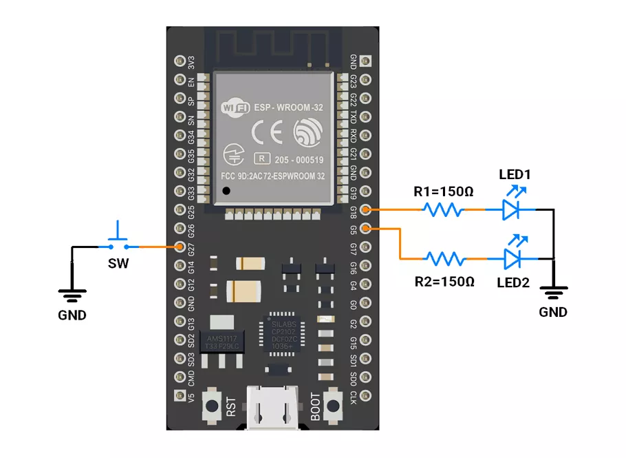
We are using the ESP32 DevKitC v4 development board and programming it using the Arduino IDE.
- Before uploading, make sure to select “ESP32 Dev Module” as the board to ensure correct settings and compatibility.
To implement the given task, we are going to use the GPIO and timer interrupt.
Hardware Connection
- Interface 2 LEDs to GPIO pins 5 and 18 with a current-limiting resistor of 150 ohms.
- Push‑Button Interfacing (Internal Pull‑up Configuration)
- One terminal to GPIO 27.
- Other terminal to GND.
- In software, configure it as INPUT_PULLUP so the pin reads HIGH when idle and LOW when pressed.
Note: Avoid using GPIOs 34–39 for push-buttons while using ESP32 because they do not support pull-up/down resistors internally.
Circuit Connection
Firmware Implementation
- Timer2 (50 ms) → Ensures stable press detection (debounce).
- Timer1 (500 ms) → Measures total press duration and counts presses.
- Interrupts → Ensure instant detection and non-blocking operation while the main loop remains busy.
Code
#include <Arduino.h>
#include "driver/gpio.h"

//Pin Definitions
#define LED1_PIN 5
#define LED2_PIN 18    // safe GPIO
#define BUTTON_PIN 27  // active-LOW button with internal pull-up

//Global State
volatile bool isT1running = false;
volatile bool isT2running = false;
volatile int clicksCount = 0;
volatile int t1Counter = 0;

volatile uint8_t led1State = 0;
volatile uint8_t led2State = 0;

// ESP32 Hardware Timers
hw_timer_t* timer1 = nullptr;  // 500 ms periodic window
hw_timer_t* timer2 = nullptr;  // 50 ms one-shot debounce

static const uint32_t TIMER_FREQ_HZ = 1000000UL;  // 1 MHz → 1 µs tick
static const uint32_t T1_PERIOD_US = 500000;      // 500 ms
static const uint32_t T2_DELAY_US = 50000;        // 50 ms

// IRAM-Safe Helper Functions
inline void IRAM_ATTR setLed(uint8_t pin, uint8_t level) {
  gpio_set_level((gpio_num_t)pin, level);
}

inline void IRAM_ATTR toggleLed(volatile uint8_t& s, uint8_t pin) {
  s ^= 1;
  gpio_set_level((gpio_num_t)pin, s);
}

inline int IRAM_ATTR readButton() {
  return gpio_get_level((gpio_num_t)BUTTON_PIN);  // LOW = pressed
}

//  GPIO Interrupt Service Routine — Button Press Handler
void IRAM_ATTR onButtonPress() {
  // Start 500 ms window timer if first click
  if (!isT1running && clicksCount == 0) {
    timerRestart(timer1);
    timerStart(timer1);
    isT1running = true;
  }

  // Start 50 ms debounce one-shot if not running
  if (!isT2running) {
    timerRestart(timer2);
    timerStart(timer2);
    isT2running = true;
  }
}

//  Timer2 ISR — 50 ms Debounce (One-Shot)
void IRAM_ATTR onDebounceTimer() {
  if (readButton() == 0 && isT1running) {  // still pressed after 50 ms
    clicksCount++;
  }
  timerStop(timer2);
  isT2running = false;
}

//  Timer1 ISR — 500 ms Click Window Logic
void IRAM_ATTR onClickWindowTimer() {
  t1Counter++;

  if (t1Counter == 1) {  // 500 ms after first press
    if (clicksCount > 1) {
      // Double-click → toggle LED2
      toggleLed(led2State, LED2_PIN);
      t1Counter = 3;  // skip further checks
    } else if (readButton() == 1 && clicksCount == 1) {
      // Single click (released by 500 ms) → toggle LED1
      toggleLed(led1State, LED1_PIN);
      t1Counter = 3;
    }
  } else if (t1Counter == 2) {  // 1.0 s long-press check
    if (readButton() == 0 && clicksCount == 1) {
      // Long press → turn both LEDs OFF
      led1State = 0;
      setLed(LED1_PIN, 0);
      led2State = 0;
      setLed(LED2_PIN, 0);
    }
    t1Counter = 3;
  }

  // Stop timer after sequence completes
  if (t1Counter >= 3) {
    timerStop(timer1);
    isT1running = false;
    clicksCount = 0;
    t1Counter = 0;
  }
}

void setup() {
  // Configure LEDs
  pinMode(LED1_PIN, OUTPUT);
  pinMode(LED2_PIN, OUTPUT);
  digitalWrite(LED1_PIN, LOW);
  digitalWrite(LED2_PIN, LOW);

  // Configure button input
  pinMode(BUTTON_PIN, INPUT_PULLUP);

  // Low-level GPIO setup for ISR-safe operations
  gpio_set_direction((gpio_num_t)LED1_PIN, GPIO_MODE_OUTPUT);
  gpio_set_direction((gpio_num_t)LED2_PIN, GPIO_MODE_OUTPUT);
  gpio_set_direction((gpio_num_t)BUTTON_PIN, GPIO_MODE_INPUT);

  //Create timers using migrated v3 API
  timer1 = timerBegin(TIMER_FREQ_HZ);
  timer2 = timerBegin(TIMER_FREQ_HZ);

  // Attach ISRs (v3 API — no edge parameter)
  timerAttachInterrupt(timer1, &onClickWindowTimer);
  timerAttachInterrupt(timer2, &onDebounceTimer);

  // Configure alarms (auto-enabled)
  timerAlarm(timer1, (uint64_t)T1_PERIOD_US, /*autoreload=*/true, 0);
  timerAlarm(timer2, (uint64_t)T2_DELAY_US, /*autoreload=*/false, 0);

  // Start both stopped
  timerStop(timer1);
  timerStop(timer2);

  //GPIO Interrupt using attachInterrupt()
  attachInterrupt(digitalPinToInterrupt(BUTTON_PIN), onButtonPress, FALLING);
}

void loop() {
  while (true) {
    // MCU busy with important background work
    // All user interaction handled by ISRs
  }
}
Code Explanation
1. Global Variables
isT1runningandisT2running: Flags to check if Timer1 (500 ms window) or Timer2 (50 ms debounce) is active.clicksCount: Counts button clicks.t1Counter: Counts 500 ms timeouts to identify single, double, or long press.led1State,led2State: Store LED ON/OFF states for toggling.
2. setup()
- Button: GPIO 27 configured as input with internal pull-up (active-LOW).
- Timer1: Configured for a 500 ms periodic window using the ESP32’s 1 MHz timer base.
- Timer2: Configured for 50 ms one-shot debounce delay.
- Interrupt:
attachInterrupt()triggersonButtonPress()on the falling edge (button press). - Both timers are stopped.
3. loop()
- Empty — the main CPU can do other work. All button and LED logic runs in interrupts.
4. ISRs
onButtonPress()– Triggered when the button is pressed.
Starts Timer1 (500 ms window) and Timer2 (50 ms debounce).onDebounceTimer()– Runs after 50 ms; if button still pressed, increments clicksCount.onClickWindowTimer()– Every 500 ms:- If clicksCount > 1 → double click → toggle LED2.
- If clicksCount == 1 and released → single click → toggle LED1.
- If clicksCount == 1and button hold pressed >1 s → long press → turn both LEDs OFF.
Stops Timer1 and resets flags afterward.
Timer Calculation
- Timer frequency = 1MHz
- 1 tick = 1/ 1MHz = 1 µs
- Number of ticks required to generate a delay
- For 500ms → 500ms / 1 µs → 500000
- For 50 ms → 50ms / 1 µs → 50000
We are using the Arduino UNO development board and programming it using the Arduino IDE.
- Before uploading, make sure to select “Arduino UNO” as the board to ensure correct settings and compatibility.
We will use external and timer interrupts for button detection.
- Interrupts on Arduino Uno:
- External Interrupts:
- INT0 (Pin 2, higher priority).
- INT1 (Pin 3).
- Timer Interrupts:
- Timer0, Timer1, and Timer2 are available.
- External Interrupts:
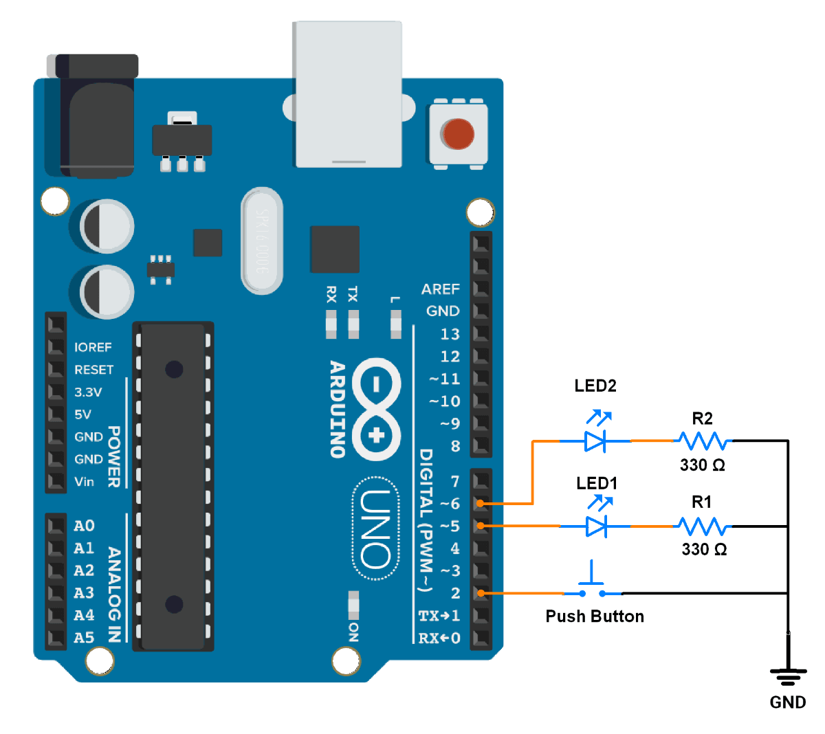
Hardware Connection
- Push button → Pin 2 (using internal pull-up)
- LED1 → Pin 5
- LED2 → Pin 6
- Use a 330 Ohm resistor for each LED to limit current to 10mA
Circuit Connection
Firmware
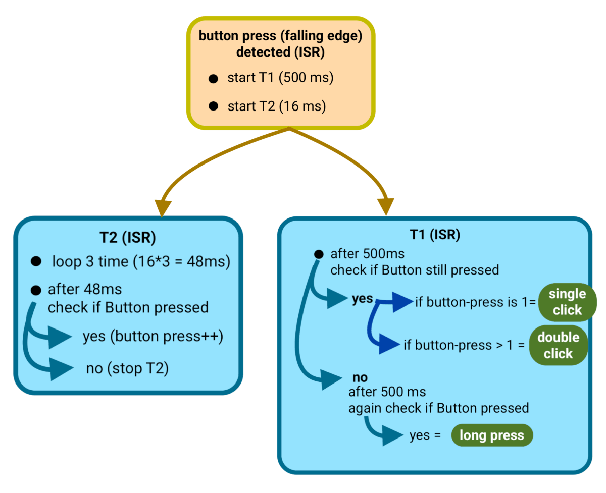
Logic to detect button presses
Code
#define LED1_PIN 5    // Pin for LED1
#define LED2_PIN 6    // Pin for LED2
#define BUTTON_PIN 2  // Pin for the button

volatile bool isT1running = false;  // Flag to indicate if Timer1 is running
volatile bool isT2running = false;  // Flag to indicate if Timer2 is running
volatile int clicksCount = 0;       // Counter for button clicks
volatile int t1Counter = 0;         // Counter for Timer1 compare events
volatile int t2Counter = 0;         // Counter for Timer2 compare events

void setup() {
  pinMode(LED1_PIN, OUTPUT);          // Set LED1 pin as output
  pinMode(LED2_PIN, OUTPUT);          // Set LED2 pin as output
  pinMode(BUTTON_PIN, INPUT_PULLUP);  // Set button pin as input with pull-up resistor

  // Configure Timer1 for a 500ms timeout
  TCCR1A = 0;              // Set Timer1 to Normal mode
  TCCR1B = 0;              // Stop Timer1
  OCR1A = 31249;           // Set compare value for 500ms
  TCNT1 = 0;               // Reset Timer1 counter
  TIMSK1 = (1 << OCIE1A);  // Enable Timer1 Compare Match A interrupt

  // Configure Timer2 for debounce logic
  TCCR2A = (1 << WGM21);   // Set Timer2 to CTC mode
  TCCR2B = 0;              // Stop Timer2
  OCR2A = 255;             // Set compare value for debounce duration
  TCNT2 = 0;               // Reset Timer2 counter
  TIMSK2 = (1 << OCIE2A);  // Enable Timer2 Compare Match A interrupt

  // Configure external interrupt for the button (INT0)
  attachInterrupt(digitalPinToInterrupt(BUTTON_PIN), ISR_INT0, FALLING);

  // Enable global interrupts
  sei();
}

void loop() {
  while (true) {
    //In this loop Microcontroller is busy in monitoring and performing important tasks constantly.
  }
}

// Interrupt Service Routine for button press (INT0)
void ISR_INT0() {
  // If Timer1 is not running and no clicks are counted yet, start Timer1
  if (!isT1running && clicksCount == 0) {
    TCCR1B = (1 << WGM12) | (1 << CS12);  // Start Timer1
    isT1running = true;
  }

  // Start Timer2 for debounce logic if it's not running
  if (!isT2running) {
    TCCR2B = (1 << CS22) | (1 << CS21) | (1 << CS20);  // Start Timer2
    isT2running = true;
  }
}

// Interrupt Service Routine for Timer2 (Debounce logic)
ISR(TIMER2_COMPA_vect) {
  t2Counter++;
  if (t2Counter >= 3) {  // After debounce duration (~3 cycles)
    if (digitalRead(BUTTON_PIN) == LOW && isT1running) {
      clicksCount++;  // Increment click count if button is still pressed
    }
    TCCR2B = 0;           // Stop Timer2
    isT2running = false;  // Reset debounce flag
    t2Counter = 0;        // Reset Timer2 counter
  }
}

// Interrupt Service Routine for Timer1 (Click detection logic)
ISR(TIMER1_COMPA_vect) {
  t1Counter++;

  if (t1Counter == 1) {  // First timeout (500ms after button press)
    if (clicksCount > 1) {
      digitalWrite(LED2_PIN, !digitalRead(LED2_PIN));  // Toggle LED2 on double-click
      t1Counter = 3;                                   // Skip further checks
    } else if (digitalRead(BUTTON_PIN) == HIGH && clicksCount == 1) {
      digitalWrite(LED1_PIN, !digitalRead(LED1_PIN));  // Toggle LED1 on single click
      t1Counter = 3;                                   // Skip further checks
    }
  } else if (t1Counter == 2) {  // Second timeout (long press detected)
    if (digitalRead(BUTTON_PIN) == LOW && clicksCount == 1) {
      digitalWrite(LED1_PIN, LOW);  // Turn off LED1
      digitalWrite(LED2_PIN, LOW);  // Turn off LED2
    }
    t1Counter = 3;  // Ensure Timer1 stops
  }

  if (t1Counter >= 3) {   // Stop Timer1 after logic completion
    TCCR1B = 0;           // Stop Timer1
    isT1running = false;  // Reset Timer1 running flag
    clicksCount = 0;      // Reset click counter
    t1Counter = 0;        // Reset Timer1 counter
  }
}
Code Explanation
1. Global Variables
- is
T1runningand isT2running: Flags to track if Timer1 and Timer2 are active. clicksCount: Counts the number of button clicks.t1Counterandt2Counter: Counters for Timer1 and Timer2 interrupts loops.
2. setup() Function
- Button Configuration:
BUTTON_PINis set as an input with a internal pull-up resistor. - Timer1 Configuration:
- Configured for a 500ms timeout using a 16MHz clock and a prescaler of 256.
- Compare value
OCR1Ais set to 31249 for 500 ms.
- Timer2 Configuration:
- Configured for debounce logic using a prescaler of 1024.
- Compare value
OCR2Ais set to 255 for 16 ms.
- External Interrupt:
- INT0 is configured to trigger on the falling edge of the button press.
- Global Interrupts: Enabled using
sei().
3. loop() Function
- The
loop()performing important tasks and all the logic is handled by interrupts.
4. Interrupt Service Routines (ISRs)
Button Press ISR (ISR_INT0)
- Start Timer1 if it is not already running and button-clicks = 0.
- Used to detect single-click, double-click, and long-press events.
- Start Timer2 if it is not already running.
- Used for debouncing a button press.
Timer2 ISR (Debounce Logic)
- Debounce Logic:
- After 3 cycles (debounce duration), the button state is checked.
- If the button is still pressed,
clicksCountis incremented. - Timer2 is stopped, and its flags are reset.
Timer1 ISR (Click Detection Logic)
- First Timeout (500ms):
- If
clicksCount > 1, it's a double-click: toggle LED2. - If
clicksCount == 1and the button is released, it's a single click: toggle LED1.
- If
- Second Timeout (1000ms):
- If the button is still pressed and
clicksCount == 1, it's a long press: turn off both LEDs.
- If the button is still pressed and
- Stop Timer1:
- After completing the logic, Timer1 is stopped, and all flags are reset.
Output
Hardware Setup