41. SPI Dice Roll
For this task, two microcontrollers are used to communicate via SPI
- Master Microcontroller: Initiates SPI communication and reads random numbers when a button is pressed.
- Slave Microcontroller: Acts as a dice roller, generating a random number between 1 and 6 when requested by the master.
In the given example code, the Slave device is configured in SPI Mode 2, where CPOL = 1 and CPHA = 0.
SPI Communication Modes
SPI communication mode is defined by two parameters
- CPOL (Clock Polarity): Defines the idle state of the clock.
- CPHA (Clock Phase): Defines when data is captured and propagated.
| Mode | CPOL | CPHA | Output Edge | Data Capture |
|---|---|---|---|---|
| SPI_MODE0 | 0 | 0 | Falling | Rising |
| SPI_MODE1 | 0 | 1 | Rising | Falling |
| SPI_MODE2 | 1 | 0 | Rising | Falling |
| SPI_MODE3 | 1 | 1 | Falling | Rising |
Slave SPI Configuration (Dice Roller)
- Mode: SPI Mode 2 → CPOL = 1, CPHA = 0
- Clock: SCK is idle high.
- Data Timing: Captured on the falling edge, changed on the rising edge.
- Frame Format: 8-bit, MSB first.
- Operation: Generates a random number (1–6) on each master request and sends it over SPI.
This configuration ensures that the master and slave remain synchronised in data exchange.
Master SPI Configuration
- Mode: SPI Mode 2 (CPOL = 1, CPHA = 0).
- Data Size: 8-bit, MSB first.
- SS/CS: Software-controlled GPIO (active-low).
- Clock Speed: Prescaler adjusted to achieve ~100 kHz SCK frequency.
- Pin Configuration:
- MOSI, MISO, SCK → Push-pull mode (default for most MCUs).
- MISO → Configured as input.
Hardware Connections
| Master Pin | Slave Pin | Description |
|---|---|---|
| MOSI | MOSI | Master Out --> Slave In |
| MISO | MISO | Master In <-- Slave Out |
| SCK | SCK | Shared SPI Clock |
| CS/SS | CS/SS | Slave Select - active low |
| GND | GND | Common Ground Reference |
Button
- Connected to Master GPIO with internal pull-up (active-low).
- Button press → Logic LOW input to trigger SPI read.
Button Handling & Debouncing
- Debounce Method
- Simple delay: 20–50 ms, or
- Timer-based debounce for stable detection.
- Each debounced press triggers a single SPI transaction where the master reads the dice value from the slave.
By connecting the push-button to the master and configuring SPI in Mode 2 (matching the slave configuration), stable and synchronized communication is achieved.
When the button is pressed, the master requests a random number (1–6) from the slave and displays or uses the value accordingly.
Below are the solutions to the given task using different microcontrollers
- STM32 as master
- ESP32 as master
- Arduino UNO
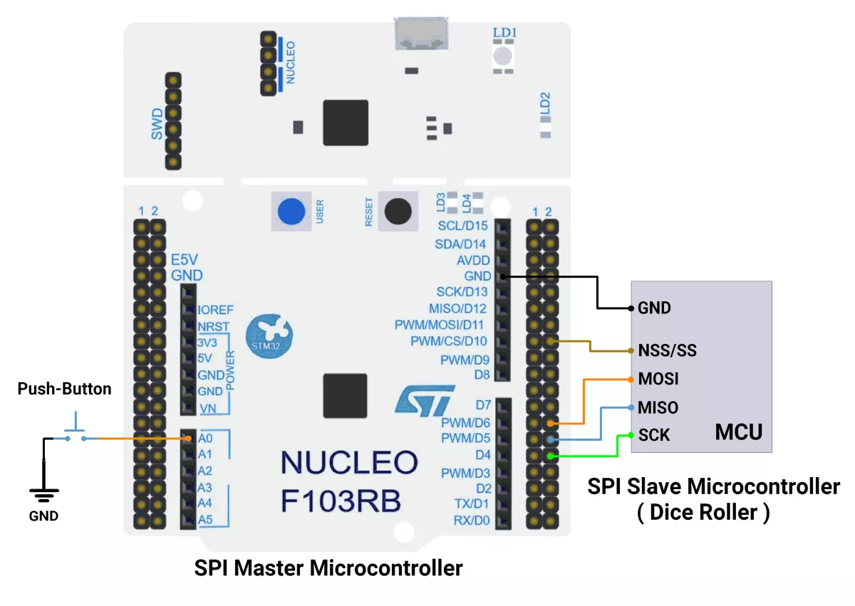
We’re using an STM32 NUCLEO-F103RB board both as master and slave, which operates at a 3.3V logic level.
Key Peripherals Used:
- SPI2: For SPI communication between the master and the slave.
- GPIO: For connecting the push-button switch and LED.
- USART2: For serial communication with a serial terminal to display messages.
Hardware Connection
Common SPI Lines
- SCK ↔ PB13 (SPI2_SCK), the master drives the clock.
- MOSI ↔ PB15 (SPI2_MOSI), master-to-slave data.
- MISO ↔ PB14 (SPI2_MISO), slave-to-master data.
- NSS/CS ↔ PB12 (SPI2_NSS), driven by master, connected to slave NSS or as a GPIO-controlled chip-select.
- GND: Common ground between master and slave.
- 3.3V: Optional if powering both boards from one source; otherwise, power independently and share GND only.
Master Board (NUCLEO-F103RB)
- Push-button: PA0 (A0) configured as input with pull-up.
- SPI2 pins:
- PB13: SCK
- PB14: MISO
- PB15: MOSI
- PB12: NSS/CS (GPIO output, controlled low during transfers)
Circuit Diagram
Firmware Implementation
STM32 as a Master
Project Setup in STM32CubeIDE
- Create a Project
- Open STM32CubeIDE, start a new project, and select the NUCLEO-F103RB board.
- Basic Configuration (via CubeMX inside CubeIDE)
- Clock: Use the default HSI oscillator with PLL enabled (as configured in SystemClock_Config).
- GPIO: Enable clocks for PORTA, PORTB, PORTC, and PORTD.
- Push-Button: Set GPIO PA0 as a GPIO Input Pull-Up
- SPI2 Configuration:
- Mode: Full Duplex Master (SPI_MODE_MASTER)
- Data Line: 2-line full duplex (SPI_DIRECTION_2LINES) → supports both MOSI and MISO
- Data Size: 8-bit (SPI_DATASIZE_8BIT)
- Clock Polarity (CPOL): High (SPI_POLARITY_HIGH) → Clock idle state is HIGH
- Clock Phase (CPHA): Data sampled on first edge (SPI_PHASE_1EDGE)
- NSS (Slave Select): Software-controlled (SPI_NSS_SOFT)
- Baud Rate: Prescaler 32 (SPI_BAUDRATEPRESCALER_32)
- Data Order: MSB first (SPI_FIRSTBIT_MSB)
- TI Mode: Disabled (SPI_TIMODE_DISABLE)
- CRC Calculation: Disabled (SPI_CRCCALCULATION_DISABLE)
- CRC Polynomial: 10 (not used since CRC is disabled)
- Interrupt: Enable SPI2 Global Interrupt in NVIC.
- USART2: Configure for asynchronous communication, default settings (115200 baud).
- Code Generation
- CubeMX will automatically generate all the startup code, including:
HAL_Init()→ Initializes HAL and system tick.SystemClock_Config()→ Configures system clock (HSI + PLL).MX_GPIO_Init()→ Initializes GPIO ports.MX_USART2_UART_Init()→ Configures UART2.MX_SPI2_Init()→ Configures I2C1.
- This code sets up the hardware and prepares the project for firmware development, so we only need to add our application logic in the user code sections
- CubeMX will automatically generate all the startup code, including:
Code Snippets from main.c
SPI Initialization (Generated by CubeMX)
static void MX_SPI2_Init(void) {
  hspi2.Instance = SPI2;
  hspi2.Init.Mode = SPI_MODE_MASTER;
  hspi2.Init.Direction = SPI_DIRECTION_2LINES;
  hspi2.Init.DataSize = SPI_DATASIZE_8BIT;
  hspi2.Init.CLKPolarity = SPI_POLARITY_HIGH;
  hspi2.Init.CLKPhase = SPI_PHASE_1EDGE;
  hspi2.Init.NSS = SPI_NSS_SOFT;
  hspi2.Init.BaudRatePrescaler = SPI_BAUDRATEPRESCALER_32;
  hspi2.Init.FirstBit = SPI_FIRSTBIT_MSB;
  hspi2.Init.TIMode = SPI_TIMODE_DISABLE;
  hspi2.Init.CRCCalculation = SPI_CRCCALCULATION_DISABLE;
  hspi2.Init.CRCPolynomial = 10;
  if (HAL_SPI_Init(&hspi2) != HAL_OK)
  {
    Error_Handler();
  }
}
Configures SPI2 in master mode, 8-bit data, CPOL = High, CPHA = 1st edge, and software-controlled CS.
Header includes and Private defines
#include <stdbool.h>
#include <stdio.h>
#include <string.h>

#define SPI2_CS_PIN GPIO_PIN_12
#define SPI2_CS_PORT GPIOB

#define SWITCH_PIN GPIO_PIN_0
#define SWITCH_PORT GPIOA
Defines pin and port mappings for SPI2 chip select (CS) and a switch input (GPIO).
SPI Transmission
/**
  * @brief Transmits and receives one byte over SPI2
  * @param data: Byte to transmit
  * @retval Received byte
  */
uint8_t SPI2_TransmitReceiveByte(uint8_t data)
{
  uint8_t rxData;

  // Pull CS low to select the device
  SPI2_CS_Enable(true);

  // Transmit and receive data
  HAL_SPI_TransmitReceive(&hspi2, &data, &rxData, 1, HAL_MAX_DELAY);

  // Pull CS high to deselect the device
  SPI2_CS_Enable(false);

  return rxData;
}- Sends one byte and receives one back.
- CS line is asserted low before transfer and released high afterward.
CS Control
/**
  * @brief Controls the Chip Select line
  * @param enable: true to select device (CS low), false to deselect (CS high)
  */
void SPI2_CS_Enable(bool enable)
{
  HAL_GPIO_WritePin(SPI2_CS_PORT, SPI2_CS_PIN, enable ? GPIO_PIN_RESET : GPIO_PIN_SET);
}
Controls the SPI2 CS pin state (low = enable, high = disable).
Main Loop (Button-Triggered SPI Transmission)
uint8_t txData = 0x00;  // Data to transmit
uint8_t rxData = 0;
uint8_t uartTXBuff[100];
while (1) {
  if (HAL_GPIO_ReadPin(SWITCH_PORT, SWITCH_PIN) == GPIO_PIN_RESET) {

    // Transmit Dummy data and receive response
    rxData = SPI2_TransmitReceiveByte(txData);

    if (rxData > 0 && rxData <= 7) {
      sprintf((char *)uartTXBuff, "You :dice: rolled a %d \n", rxData);
    } else {
      sprintf((char *)uartTXBuff, "Dice roller not working. Retry after some time and please check circuit connections \n");
    }

    HAL_UART_Transmit(&huart2, uartTXBuff, strlen((const char *)uartTXBuff), HAL_MAX_DELAY);


    // You can add a delay or other logic here for switch Debouncing
    HAL_Delay(500);
  }
}- When the switch is pressed, the MCU sends a dummy byte over SPI2 and reads back a response.
- If the response (rxData) is between 1–7, it’s treated as a dice roll and the result is sent over UART2.
- Otherwise, an error message is sent over the UART.
- A 500 ms delay is added for switch debouncing.
Expected Output
- When the button is pressed, the STM32 transmits 0x00 or 0x01 alternately over SPI.
- The slave device (e.g., shift register) should toggle an LED accordingly.
Download Project
The complete STM32CubeIDE project (including .ioc configuration, main.c, and HAL files) is available here:
We are using the ESP32 DevKitC v4 development board and programming it using the Arduino IDE.
- Before uploading, make sure to select “ESP32 Dev Module” as the board to ensure correct settings and compatibility.
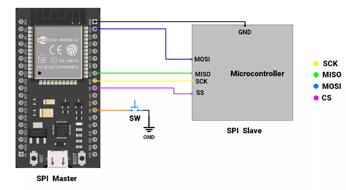
Hardware Connection
Master ( ESP32 ) interfacing with a slave microcontroller
- Master SCK (pin 18) → slave SCK
- Master MISO (pin 19) → slave MISO
- Master MOSI (pin 23) → slave MOSI
- Master SS (pin 5) → slave SS
- Master GND → slave GND
Circuit Diagram
Firmware
Code(Master)
#include <SPI.h>  // Include SPI library

// Pin Definitions
#define BUTTON_PIN 4  // GPIO for button input
#define CS_PIN 5      // Chip Select (connect to slave CS pin)


// Button Debounce Variables
unsigned long debounce_duration = 50;  // Debounce time (ms)
int previous_button_state = HIGH;
int current_button_state = HIGH;
unsigned long last_debounce_time = 0;

// SPI Settings
// 4 MHz SPI clock, MSB first, Mode 2
SPISettings spiSettings(4000000, MSBFIRST, SPI_MODE2);

void setup() {
  Serial.begin(115200);

  // Initialize button pin with internal pull-up
  pinMode(BUTTON_PIN, INPUT_PULLUP);

  // Initialize CS pin for SPI
  pinMode(CS_PIN, OUTPUT);
  digitalWrite(CS_PIN, HIGH);  // Deselect slave initially

  // Start SPI on ESP32 VSPI bus
  SPI.begin(18, 19, 23, CS_PIN);  // SCK=18, MISO=19, MOSI=23, CS=5

  Serial.println("Click the button 🎲 to roll the dice:");
}

void loop() {
  if (debounced_button_press_check(BUTTON_PIN, LOW)) {
    byte masterReceive = 0;

    // Begin SPI communication
    SPI.beginTransaction(spiSettings);
    digitalWrite(CS_PIN, LOW);  // Select the slave

    // Send dummy byte (0) and receive response
    masterReceive = SPI.transfer(0);

    digitalWrite(CS_PIN, HIGH);  // Deselect the slave
    SPI.endTransaction();

    // Display result from slave
    if (masterReceive > 0 && masterReceive < 7) {
      Serial.print("You 🎲 rolled a ");
      Serial.print(masterReceive);
      Serial.println(" !");
    } else {
      Serial.println("Dice roller not responding properly. Check connections.");
    }
  }
}


// Debounce Function
bool debounced_button_press_check(int pin, bool expected_state) {
  int button_reading = digitalRead(pin);

  // Detect state change
  if (button_reading != previous_button_state) {
    last_debounce_time = millis();
  }
  previous_button_state = button_reading;

  // Check for stable input beyond debounce duration
  if ((millis() - last_debounce_time) > debounce_duration) {
    if (button_reading != current_button_state) {
      current_button_state = button_reading;
      if (current_button_state == expected_state) {
        return true;
      }
    }
  }
  return false;
}
Code Explanation
- SPI.begin(18, 19, 23, CS_PIN):
Initializes SPI communication on the ESP32 VSPI bus using pins SCK (18), MISO (19), MOSI (23), and CS (5). - SPISettings(4000000, MSBFIRST, SPI_MODE2):
Configures SPI to operate at 4 MHz, with MSB first, and in Mode 2 (CPOL = 1, CPHA = 0) for correct clock phase and polarity. - digitalWrite(CS_PIN, HIGH):
Keeps the Chip Select (CS) line HIGH when idle (no communication).
During communication, CS is pulled LOW to activate the slave. - SPI.transfer(0):
- Sends a dummy byte (0) to the slave and simultaneously reads the response from it.
- In this project, the slave sends back a random number between 1 and 6 representing the dice roll.
- if (masterReceive > 0 && masterReceive < 7):
- Validates the received data.
If the value is within 1–6, it is treated as a valid dice roll result; otherwise, it indicates an error or an uninitialized slave.
- Validates the received data.
- debounced_button_press_check(BUTTON_PIN, LOW):
- Checks if the button has transitioned from HIGH to LOW (pressed state) with debounce protection.
- When the button is pressed, the master sends data to the slave, receives the random number, and prints the dice result on the Serial Monitor.
We are using the Arduino UNO development board and programming it using the Arduino IDE.
- Before uploading, make sure to select “Arduino UNO” as the board to ensure correct settings and compatibility.
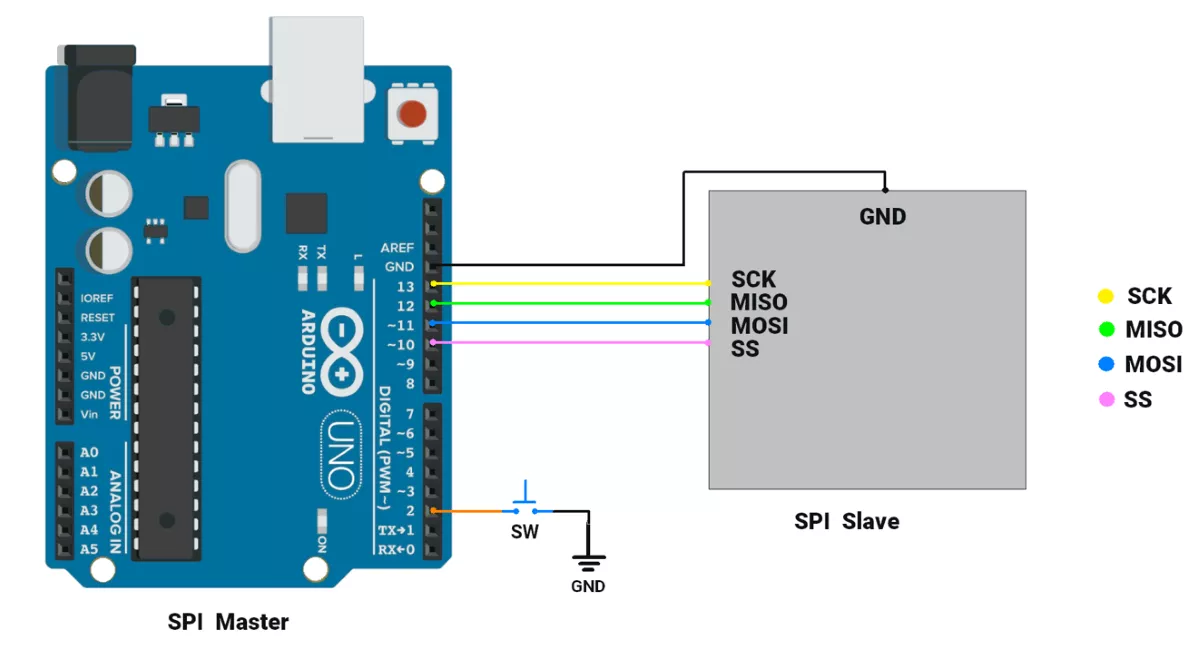
Hardware Connection
Master (Arduino UNO) interfacing with a slave microcontroller
- Master SCK (pin 13) → slave SCK
- Master MISO (pin 12) → slave MISO
- Master MOSI (pin 11) → slave MOSI
- Master SS (pin 7) → slave SS
Circuit Connection
Code (SPI Master)
#include <SPI.h>  // Include SPI library for communication
#define buttonPin 2
/* all the variables declared below are for button Debouncing detection purposes */
unsigned long debounce_duration = 50;  // Minimum time to debounce button (in milliseconds)
int previous_button_state = HIGH;      // Previous state of the button
int current_button_state = HIGH;       // Current state of the button
unsigned long last_debounce_time = 0;  // Time when button state last changed
unsigned long press_start_time;        // Time when button press starts
unsigned long release_time;            // Duration of the button press

void setup() {
  Serial.begin(115200);
  // Initialize button GPIO
  pinMode(buttonPin, INPUT_PULLUP);
  // Start SPI communication as master
  SPI.begin();
  SPI.setDataMode(SPI_MODE2);
  // Set SPI clock divider to 4 (4 MHz SPI clock)
  SPI.setClockDivider(SPI_CLOCK_DIV4);
  // Set SS (Slave Select) pin to HIGH to prevent the master from selecting the slave initially
  digitalWrite(SS, HIGH);
  Serial.println("Click button to :dice: Roll a Dice : ");
}

void loop() {
  if (debounced_button_press_check(buttonPin, LOW)) {
    // byte variable to store random-number
    byte Mastereceive;
    // Begin communication with the slave by pulling SS pin LOW
    digitalWrite(SS, LOW);
    // Send x to the slave and receive the response from the slave
    Mastereceive = SPI.transfer(0);
    // check if the slave (dice roller) has returned valid value
    if (Mastereceive > 0 && Mastereceive < 7) {
      Serial.print("You :dice: rolled a ");
      Serial.print(Mastereceive);
      Serial.println(" !");
    } else {
      Serial.println("Dice roller not working. Retry after some time and please check circuit connections ");
    }
    // End communication with slave by pulling SS HIGH
    digitalWrite(SS, HIGH);
  }
}

//Checks for a debounced button press and returns true if detected, false otherwise.
bool debounced_button_press_check(int pin, bool expected_state) {
  int button_reading = digitalRead(pin);
  // If the button state has changed, reset the debounce timer
  if (button_reading != previous_button_state) {
    last_debounce_time = millis();
  }
  previous_button_state = button_reading;
  // If the state has remained stable beyond the debounce duration, consider it valid
  if ((millis() - last_debounce_time) > debounce_duration) {
    if (button_reading != current_button_state) {
      current_button_state = button_reading;
      if (current_button_state == expected_state) {
        return true;  // Return true if the desired state is detected
      }
    }
  }
  return false;  // Return false if no valid press is detected
}
Code explanation
SPI.setDataMode(SPI_MODE2): configures SPI communication to use MODE 2.SPI.setClockDivider(SPI_CLOCK_DIV4): This statement configures SPI communication to communicate at 4 MHz. (16 MHz / 4).digitalWrite(SS, HIGH): In SPI, ideally when no communication is taking place, the SS line is HIGH. But when communication is ongoing SS line should be LOW.SPI.transfer(data): This function transmits the data and returns the received data over the SPI bus.if (Mastereceive > 0 && Mastereceive < 7): Checks if the received data is in the valid range. If Dice Roller (slave) is not initialized it returns garbage value. Thus, this check is important.debounced_button_press_check(buttonPin, LOW): This function returns True if the buttonPin has transitioned from HIGH to LOW (i.e. button is pressed).
When the button is pressed, we are reading a random number & printing it on the Serial monitor.
Note: Replace the ":dice:" text with a dice icon in the code.
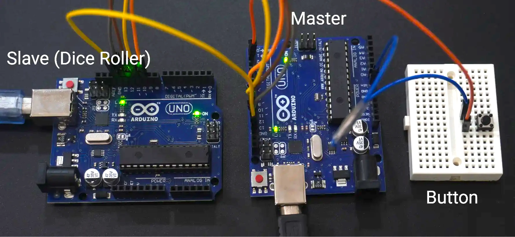
Output
The setup photo