71. UART-Based LEDs Control
In this task, we must implement bidirectional UART communication between two microcontrollers, where each controller manages local inputs and controls remote outputs through serial communication.
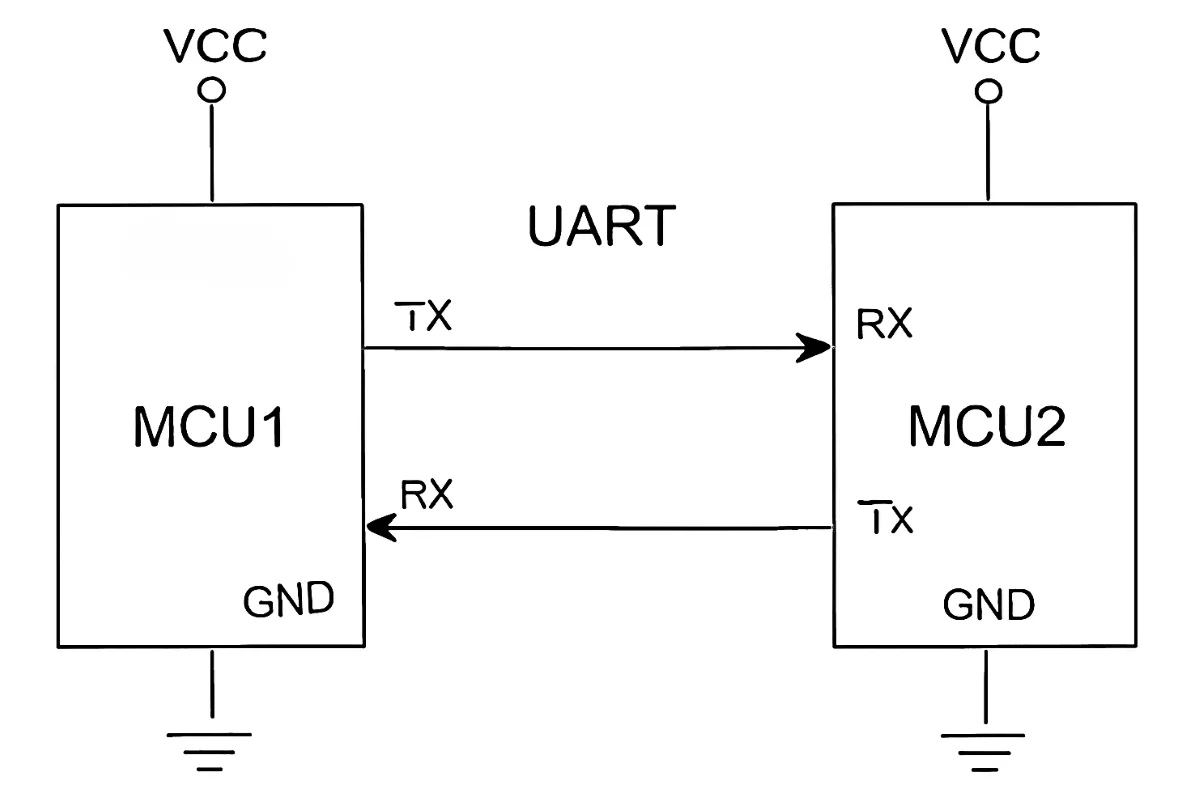
System Architecture
Cross-Control Functionality:
- Microcontroller 1: Reads the potentiometer → Controls the brightness of LED2 connected to Microcontroller 2
- Microcontroller 2: Reads push button press → Toggles LED1 ON/OFF connected to Microcontroller 1
Connection Requirements:
- TX of Microcontroller 1 → RX of Microcontroller 2
- RX of Microcontroller 1 → TX of Microcontroller 2
- The GND of both microcontrollers must be connected
Voltage Level Considerations in UART Communication
- UART is push-pull (active high/low)
- Unlike I²C, UART pins (TX, RX) actively drive logic HIGH and LOW.
- This makes voltage compatibility critical when connecting devices.
- Logic voltage matching
- 5 V TX → 3.3 V RX: Unsafe! It can exceed the 3.3 V limit and damage the pin. Always step down using a divider or level shifter.
- 3.3 V TX → 5 V RX: Often works (3.3 V is seen as HIGH), but not guaranteed at all speeds or with every chip. A shifter makes it reliable.
- Best practice: Use a level shifter both ways and always share a common ground.
Functionality
- Microcontroller 1 (Potentiometer & LED1 control)
- Reads the potentiometer value via ADC and sends it to Microcontroller 2 over UART.
- Receives button toggle command from Microcontroller 2 to control LED1 ON/OFF.
- Prints LED1 status on the Serial terminal.
- Microcontroller 2 (Push button & LED2 control)
- Reads push button state using internal pull-up and sends toggle command to Microcontroller 1.
- Receives potentiometer ADC data from Microcontroller 1, maps it to PWM, and controls LED2 brightness.
- Prints the potentiometer value on the Serial terminal.
UART Communication Protocol
- Framing: 8-bit data, No parity, Baud: 115,200bps (example).
- Commands sent from Microcontroller 2 to Microcontroller 1:
- 0: Trigger ADC conversion on Microcontroller 1.
- 1 and 2: Request the lower and upper bytes of ADC maximum value (e.g., 4095 for 12-bit).
- 3 and 4: Request the lower and upper bytes of the last ADC reading.
- ‘T’: Toggle LED1 on Microcontroller 1.
- Transaction Flow
- MCU2 periodically (e.g., every 100 ms) sends commands 0–4 in sequence.
- MCU1 responds with the requested bytes.
- MCU2 reconstructs both ADC_MAX_VALUE and ADC_VALUE from the received data.
Why send ADC Maximum Value along with the current ADC value?
- Purpose: The receiver needs to know the ADC’s full-scale range (e.g., 4095 for 12-bit) to interpret raw readings.
- Example: If ADC_VALUE = 2048 and ADC_MAX_VALUE = 4095, the system knows it represents ~50% of the full range.
Data Packing
- Both ADC_MAX_VALUE and ADC_VALUE are split into two bytes (little-endian format):
- Bytes 1–2: ADC_MAX_VALUE (low byte, high byte).
- Bytes 3–4: ADC_VALUE (low byte, high byte).
- The receiver reassembles these values for accurate scaling and processing.
Serial Terminal Output
Both microcontrollers provide real-time feedback through their respective serial monitors:
- Microcontroller 1: Displays LED1 status as "LED1 Status: ON" or "LED1 Status: OFF"
- Microcontroller 2: Shows received ADC values as "Received ADC Value: [receivedADCValue]"
So, by connecting and configuring the microcontrollers and UART communication, we can implement the task.
Below are the solutions to the given task using different microcontrollers
- STM32
- ESP32
- Arduino UNO
We’re using an STM32 NUCLEO-F103RB board, which operates at a 3.3V logic level.
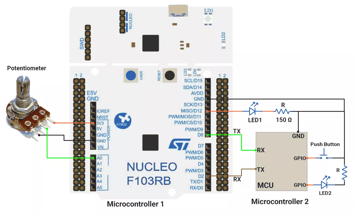
A) STM32 as Microcontroller 1 Solution
Key Peripherals Used:
- ADC1 – Reads the analog voltage from the potentiometer.
- GPIO – To connect the LED.
- USART1 – Provides serial communication between two boards.
- USART2 – Provides serial communication with a terminal.
STM32 Hardware Connection
- Connect the middle terminal of the potentiometer to the analog GPIO pin PA0(A0) and the outer terminals to 3.3V and GND.
- Connect the anode of the LED to GPIO pin PA6(D12) and the cathode to GND through a current-limiting resistor.
- UART1:
- TX of Microcontroller1 PA9(D8) → RX of Microcontroller 2
- RX of Microcontroller1 PA10(D2) → TX of Microcontroller 2
- The GND of both microcontrollers must be connected
- UART2: Connect the USB cable to the PC for power and UART communication with the serial terminal.
Circuit Diagram
Note: When interfacing UART devices operating at different voltages (e.g., 5 V ↔ 3.3 V), always use a voltage level shifter to ensure safe and reliable communication.
STM32 Firmware Implementation
Project Setup in STM32CubeIDE
- Create a Project
- Open STM32CubeIDE, start a new project, and select the NUCLEO-F103RB board.
- Basic Configuration (via CubeMX inside CubeIDE)
- Clock: Use the default HSI oscillator with PLL enabled (as configured in SystemClock_Config).
- GPIO: Enable clocks for PORTA, PORTB, PORTC, and PORTD.
- LED: Set PA6(D12) as GPIO Output Push-Pull
- ADC1 (Analog Input Source)
- Resolution: 12-bit (0–4095 range).
- Conversion mode: Single, software-triggered.
- Channel: ADC_CHANNEL_0 (PA0).
- UART1 and UART2
- Configure both with the below configurations
- Set Mode to Asynchronous
- Configure parameters:
- Baud Rate: 115200
- Word Length: 8 bits
- Parity: None
- Stop Bits: 1
- Hardware Flow Control: None
- Interrupt: Enable UART1 Global Interrupt in NVIC.
- The NUCLEO-F103RB board has USART2 connected to the ST-LINK virtual COM port (PA2 and PA3)
- Code Generation
- CubeMX will automatically generate all the startup code, including:
HAL_Init()→ Initializes HAL and system tick.SystemClock_Config()→ Configures system clock (HSI + PLL).MX_GPIO_Init()→ Initializes GPIO ports.MX_USART1_UART_Init()→ Configures UART1.MX_USART2_UART_Init()→ Configures UART2.MX_ADC1_Init()→ Configures ADC1.
- This code sets up the hardware and prepares the project for firmware development, so we only need to add our application logic in the user code sections
- CubeMX will automatically generate all the startup code, including:
Code Snippets from main.c
ADC Initialization (MX_ADC1_Init)
  hadc1.Instance = ADC1;
  hadc1.Init.ScanConvMode = ADC_SCAN_DISABLE;
  hadc1.Init.ContinuousConvMode = DISABLE;
  hadc1.Init.DiscontinuousConvMode = DISABLE;
  hadc1.Init.ExternalTrigConv = ADC_SOFTWARE_START;
  hadc1.Init.DataAlign = ADC_DATAALIGN_RIGHT;
  hadc1.Init.NbrOfConversion = 1;
  if (HAL_ADC_Init(&hadc1) != HAL_OK) {
    Error_Handler();
  }

  sConfig.Channel = ADC_CHANNEL_0;
  sConfig.Rank = ADC_REGULAR_RANK_1;
  sConfig.SamplingTime = ADC_SAMPLETIME_239CYCLES_5;
  if (HAL_ADC_ConfigChannel(&hadc1, &sConfig) != HAL_OK) {
    Error_Handler();
}- Initializes ADC1 in single-channel mode, software-triggered conversion, with Channel 0 configured for a 239.5-cycle sampling time.
GPIO Initialization (MX_GPIO_Init)
 /*Configure GPIO pin : PA6 */
 GPIO_InitStruct.Pin = GPIO_PIN_6;
 GPIO_InitStruct.Mode = GPIO_MODE_OUTPUT_PP;
 GPIO_InitStruct.Pull = GPIO_NOPULL;
 GPIO_InitStruct.Speed = GPIO_SPEED_FREQ_LOW;
HAL_GPIO_Init(GPIOA, &GPIO_InitStruct);- PA6 as output push-pull (for LED control).
- No pull resistor, low-speed (GPIO_SPEED_FREQ_LOW).
UART Initialization (MX_USART1_UART_Init and MX_USART2_UART_Init)
 huart2.Instance = USART2;
 huart2.Init.BaudRate = 115200;
 huart2.Init.WordLength = UART_WORDLENGTH_8B;
 huart2.Init.StopBits = UART_STOPBITS_1;
 huart2.Init.Parity = UART_PARITY_NONE;
 huart2.Init.Mode = UART_MODE_TX_RX;
 huart2.Init.HwFlowCtl = UART_HWCONTROL_NONE;
 huart2.Init.OverSampling = UART_OVERSAMPLING_16;
 if (HAL_UART_Init(&huart2) != HAL_OK)
 {
   Error_Handler();
}- Baud rate: 115200, 8-bit data, no parity, 1 stop bit.
- Transmit/receive mode (UART_MODE_TX_RX).
- Similar for UART1 also
Header includes, private defines, and variables
#include <stdio.h>
#include <string.h>

#define ADC_MAX_VALUE 4095
#define ADC_REF_VOLTAGE 3.3
#define VOLTAGE_OFFSET 0.05

#define LED0_PORT GPIOA
#define LED0_PIN GPIO_PIN_6

char uartTXBuffer[50];     //Tx Buffer for UART messages
uint8_t uartRXByte;        // Single received byte via UART
uint8_t uartRXBuffer[30];  // Buffer to store complete UART string
uint8_t uartRXIndex = 0;   // Index for UART buffer
uint8_t receivedData[30];
volatile uint8_t byteReceivedFlag = 0;

uint32_t adcValue = 0;
const uint8_t adcMaxLowerByte = ADC_MAX_VALUE;
const uint8_t adcMaxUpperByte = ADC_MAX_VALUE >> 8;
uint8_t adcLowerByte = 0;
uint8_t adcUpperByte = 0;- Defines:
- ADC_MAX_VALUE: 4095 (12-bit ADC max).
- ADC_REF_VOLTAGE: 3.3V (reference voltage).
- VOLTAGE_OFFSET: Calibration offset (0.05V).
- Buffers:
- uartTXBuffer: Stores UART transmit messages.
- uartRXBuffer: Stores received UART data.
- ADC Variables:
- adcValue: Raw ADC reading.
- adcLowerByte/UpperByte: Split ADC value for transmission.
Utility Function and callback
/**
  * @brief  Prints a string to the serial monitor
  * @param  msg: Pointer to the null-terminated string to send
  * @retval None
  */
static void printOnSerialMonitor(const char *msg) {
  HAL_UART_Transmit(&huart2, (uint8_t *)msg, strlen(msg), HAL_MAX_DELAY);
}

/* Start UART RX interrupt for receiving one byte */
void uartStartReception() {
	HAL_UART_Receive_IT(&huart1, &uartRXByte, 1);
}

/* UART RX Complete Callback */
void HAL_UART_RxCpltCallback(UART_HandleTypeDef *huart) {
  if (huart->Instance == USART1) {
    byteReceivedFlag = 1;

    // Restart reception for next byte
    uartStartReception();
  }
}- printOnSerialMonitor: Sends strings via UART.
- HAL_UART_RxCpltCallback:
- Sets byteReceivedFlag on UART RX interrupt.
- Re-enables RX interrupt for continuous reception.
Main Loop Logic
uartStartReception();
while (1) {
  if (byteReceivedFlag) {
    byteReceivedFlag = 0;
    uint8_t receivedByte = uartRXByte;  // Read a single byte

    if (receivedByte == 'T') {
      HAL_GPIO_TogglePin(LED0_PORT, LED0_PIN);

      if (HAL_GPIO_ReadPin(LED0_PORT, LED0_PIN)) {
        sprintf(uartTXBuffer, "LED is ON\r\n");
      } else {
        sprintf(uartTXBuffer, "LED is OFF\r\n");
      }

      printOnSerialMonitor(uartTXBuffer);
    }

    if (receivedByte == 0) {

      HAL_ADC_Start(&hadc1);
      HAL_ADC_PollForConversion(&hadc1, 20);
      adcValue = HAL_ADC_GetValue(&hadc1);
      adcLowerByte = adcValue;
      adcUpperByte = adcValue >> 8;
      uint8_t uartTXByte = '0';
      HAL_UART_Transmit(&huart1, &uartTXByte, 1, HAL_MAX_DELAY);
    }

    if (receivedByte == 1) {
      HAL_UART_Transmit(&huart1, &adcMaxLowerByte, 1, HAL_MAX_DELAY);
    }

    if (receivedByte == 2) {
      HAL_UART_Transmit(&huart1, &adcMaxUpperByte, 1, HAL_MAX_DELAY);
    }

    if (receivedByte == 3) {
      HAL_UART_Transmit(&huart1, &adcLowerByte, 1, HAL_MAX_DELAY);
    }

    if (receivedByte == 4) {
      HAL_UART_Transmit(&huart1, &adcUpperByte, 1, HAL_MAX_DELAY);
    }
  }
}- Initialization:
HAL_UART_Receive_IT(&huart1, &uartRXByte, 1)→ Starts UART reception in interrupt mode.
- Loop Behavior:
- If
byteReceivedFlagis set:- Resets the flag (
byteReceivedFlag = 0). - Checks the received byte (
uartRXByte):- Case '
T':- Toggles LED (PA6).
- Sends "LED is ON/OFF" over UART2.
- Case
0:- Starts ADC conversion, reads value, and splits it into lower & upper bytes.
- Sends '0' as acknowledgment.
- Cases
1to4:- Sends ADC max value (lower/upper byte) or current ADC value (lower/upper byte).
- Case '
- Resets the flag (
- If
Flow of Operation
- The other MCU sends a command byte (
'T', 0, 1, 2, 3, or 4). - The MCU processes the command and performs the corresponding action (LED toggle / ADC read).
- If required, the MCU sends a response (status message or ADC data) back to the host.
Download Project
The complete STM32CubeIDE project (including .ioc configuration, main.c, and HAL files) is available here:
📥 Download Project
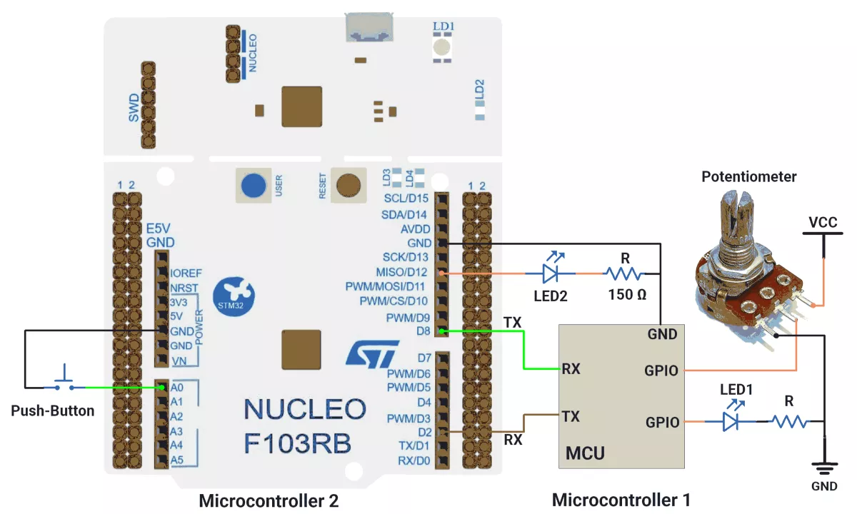
B) STM32 as Microcontroller 2
Key Peripherals Used:
- TIM3 – Generates a PWM signal to control LED brightness.
- GPIO – Reads button input with software debouncing.
- USART1 – Handles UART communication between two boards.
- USART2 – Provides serial communication with a terminal.
- SysTick Timer – Provides a millisecond time base for debounce logic.
STM32 Hardware Connection
- Connect the one terminal of the push-button switch to the GPIO pin PA0(A0) and the other terminal to GND.
- Connect the anode of the LED to GPIO pin PA6(D12) and the cathode to GND through a current-limiting resistor.
- UART1:
- TX of Microcontroller2 PA9(D8) → RX of Microcontroller 1
- RX of Microcontroller2 PA10(D2) → TX of Microcontroller 1
- The GND of both microcontrollers must be connected
- UART2: Connect the USB cable to the PC for power and UART communication with the serial terminal.
Circuit Diagram
STM32 Firmware Implementation
Project Setup in STM32CubeIDE
- Create a Project
- Open STM32CubeIDE, start a new project, and select the NUCLEO-F103RB board.
- Basic Configuration (via CubeMX inside CubeIDE)
- Clock: Use the default HSI oscillator with PLL enabled (as configured in SystemClock_Config).
- GPIO: Enable clocks for PORTA, PORTB, PORTC, and PORTD.
- LED: Set PA6(D12) as GPIO Output Push-Pull
- Push-Button: Set PA0(A0) as GPIO Input with Pull-Up
- TIM3 Configuration:
- Prescaler = 0, Counter Mode = Up, Period = 4095 (12-bit resolution)
- Channel 1 configured for PWM1, initial Pulse = 0
- UART1 and UART2
- Configure both with the below configurations
- Set Mode to Asynchronous
- Configure parameters:
- Baud Rate: 115200
- Word Length: 8 bits
- Parity: None
- Stop Bits: 1
- Hardware Flow Control: None
- Interrupt: Enable UART1 Global Interrupt in NVIC.
- The NUCLEO-F103RB board has USART2 connected to the ST-LINK virtual COM port (PA2 and PA3)
- Code Generation
- CubeMX will automatically generate all the startup code, including:
- HAL_Init() → Initializes HAL and system tick.
- SystemClock_Config() → Configures system clock (HSI + PLL).
- MX_GPIO_Init() → Initializes GPIO ports.
- MX_USART1_UART_Init() → Configures UART1.
- MX_USART2_UART_Init() → Configures UART2.
- MX_TIM3_Init() → Configures TIM3 for PWM generation.
- This code sets up the hardware and prepares the project for firmware development, so we only need to add our application logic in the user code sections
- CubeMX will automatically generate all the startup code, including:
Code Snippets from main.c
GPIO Initialization (MX_GPIO_Init)
A) PA0 Configuration (Button Input):
GPIO_InitStruct.Pin = GPIO_PIN_0;
GPIO_InitStruct.Mode = GPIO_MODE_INPUT;
GPIO_InitStruct.Pull = GPIO_PULLUP;
HAL_GPIO_Init(GPIOA, &GPIO_InitStruct);- Purpose: Configures GPIO pin PA0 as an input with internal pull-up resistor
- Details:
GPIO_PIN_0: Specifies pin 0 of GPIO port AGPIO_MODE_INPUT: Sets the pin as inputGPIO_PULLUP: Enables internal pull-up resistor (button will read HIGH when not pressed, LOW when pressed)
B) USART TX/RX Pins Configuration
GPIO_InitStruct.Pin = USART_TX_Pin|USART_RX_Pin;
GPIO_InitStruct.Mode = GPIO_MODE_AF_PP;
GPIO_InitStruct.Speed = GPIO_SPEED_FREQ_LOW;
HAL_GPIO_Init(GPIOA, &GPIO_InitStruct);- Purpose: Configures USART transmit and receive pins
- Details:
- USART_TX_Pin|USART_RX_Pin: Configures both TX and RX pins simultaneously
- GPIO_MODE_AF_PP: Sets pins to alternate function push-pull mode (required for USART)
- GPIO_SPEED_FREQ_LOW: Sets low speed (appropriate for UART communication)
UART Initialization (MX_USART1_UART_Init and MX_USART2_UART_Init)
 huart2.Instance = USART2;
 huart2.Init.BaudRate = 115200;
 huart2.Init.WordLength = UART_WORDLENGTH_8B;
 huart2.Init.StopBits = UART_STOPBITS_1;
 huart2.Init.Parity = UART_PARITY_NONE;
 huart2.Init.Mode = UART_MODE_TX_RX;
 huart2.Init.HwFlowCtl = UART_HWCONTROL_NONE;
 huart2.Init.OverSampling = UART_OVERSAMPLING_16;
 if (HAL_UART_Init(&huart2) != HAL_OK)
 {
   Error_Handler();
}- Baud rate: 115200, 8-bit data, no parity, 1 stop bit.
- Transmit/receive mode (UART_MODE_TX_RX).
- Similar for UART1 also
Header Includes, Private Defines, and Variables
A) Includes
#include <string.h>
#include <stdio.h>- Standard C libraries for string operations and stdio functions
B) Defines
#define SWITCH_PORT GPIOA
#define SWITCH_PIN GPIO_PIN_0- Macros for the switch configuration (connected to PA0)
C) Global Variables
uint32_t previousMillis = 0;
uint8_t g_debounceDuration = 50;    // Minimum time to debounce button (in milliseconds)
uint8_t g_previousButtonState = 1;  // Previous state of the button
uint8_t g_currentButtonState = 1;   // Current state of the button
uint32_t g_lastDebounceTime = 0;    // Time when button state last changed
uint32_t g_pressStartTime;          // Time when button press starts
uint32_t g_releaseTime;             // Duration of the button press

uint8_t uartTXBuffer[20];          //Tx Buffer for UART messages
uint8_t uartRXByte;                // Single received byte via UART
uint8_t uartRXBuffer[10];          // Increased buffer size
volatile uint8_t uartRXIndex = 0; // Index for UART buffer- Timing Variables: Used for debouncing and timing measurements
- UART Buffers: For storing transmitted and received data
- Button State Variables: Track button state changes for debouncing
Utility Functions and Callbacks
A) Mapping Function
uint16_t mapValue(uint16_t input, uint16_t inMin, uint16_t inMax,
                uint16_t outMin, uint16_t outMax) {
  return (input - inMin) * (outMax - outMin) / (inMax - inMin) + outMin;
}- Purpose: Linearly maps a value from one range to another
- Usage: Used to scale ADC values to PWM duty cycle range
B) Millis Function
uint32_t millis() {
  return HAL_GetTick();
}- Purpose: Provides milliseconds since startup (wrapper for HAL_GetTick)
C) Button Debounce Function
//Checks for a debounced button press and returns true if detected, false otherwise.
uint8_t debouncedButtonPressCheck(GPIO_TypeDef *GPIOx, uint16_t GPIO_Pin,
                                  uint8_t expectedState) {
  uint8_t buttonReading = HAL_GPIO_ReadPin(GPIOx, GPIO_Pin);

  // If the button state has changed, reset the debounce timer
  if (buttonReading != g_previousButtonState) {
    g_lastDebounceTime = millis();
  }
  g_previousButtonState = buttonReading;

  // If the state has remained stable beyond the debounce duration, consider it valid
  if ((millis() - g_lastDebounceTime) > g_debounceDuration) {
    if (buttonReading != g_currentButtonState) {
      g_currentButtonState = buttonReading;
      if (g_currentButtonState == expectedState) {
        return 1;  // Return true if the desired state is detected
      }
    }
  }
  return 0;  // Return false if no valid press is detected
}- Purpose: Checks for a debounced button press
- Logic:
- Reads current button state
- Resets debounce timer if state changes
- Only returns true if state remains stable beyond debounce duration
- Returns true only when button reaches expected state
UART Callbacks and Helpers
/* Start UART RX interrupt for receiving one byte */
void uartStartReception() {
  HAL_UART_Receive_IT(&huart1, &uartRXByte, 1);
}

/* UART RX Complete Callback */
void HAL_UART_RxCpltCallback(UART_HandleTypeDef *huart) {
  if (huart->Instance == USART1) {
    uartRXBuffer[uartRXIndex++] = uartRXByte;  // Store byte

    // Restart reception for next byte
    uartStartReception();
  }
}

void transmitByteOnUART1(uint8_t byte) {
  HAL_UART_Transmit(&huart1, &byte, 1, HAL_MAX_DELAY);
}
- Purpose: Handle UART communication
- Features:
- Interrupt-based reception
- Byte-by-byte transmission
- Buffer management
Main Loop Logic
A) Initialization
HAL_TIM_PWM_Start(&htim3, TIM_CHANNEL_1);
uartStartReception();- Starts PWM generation on TIM3 Channel 1
- Begins UART reception in interrupt mode
B) Main Loop
while (1) {
  // Main processing every 100ms
  if ((millis() - previousMillis) > 100) {
    previousMillis = millis();

    // Transmit test sequence
    for (uint8_t i = 0; i < 5; i++) {
      transmitByteOnUART1(i);
      HAL_Delay(1);
    }

    // Process received ADC data
    uint16_t adcMaxValue = (uartRXBuffer[2] << 8) | uartRXBuffer[1];
    uint16_t adcValue = (uartRXBuffer[4] << 8) | uartRXBuffer[3];

     sprintf(uartTXBuffer, "ADC Value = %d\r\n",(int)adcValue);

     printOnSerialMonitor(uartTXBuffer);

    // Map to PWM range and update
    uint16_t brightness = mapValue(adcValue, 0, adcMaxValue, 0, 4095);
    __HAL_TIM_SET_COMPARE(&htim3, TIM_CHANNEL_1, brightness);
  }

  // Check for button press
  if (debouncedButtonPressCheck(SWITCH_PORT, SWITCH_PIN, 0)) {
    transmitByteOnUART1('T');
  }
}
Flow of Operation
- Initialization:
- PWM and UART peripherals are initialized
- UART reception is started in interrupt mode
- Main Loop Execution:
- Every 100ms:
- Transmits a command sequence (0-4) via UART
- Processes received ADC data
- Prints ADC values on the serial terminal.
- Maps received ADC value to PWM range (0-4095)
- Updates the PWM duty cycle based on the mapped value
- Continuously checks for button presses:
- When debounced press is detected, transmit 'T' via UART
- Every 100ms:
- Interrupt Handling:
- UART receive interrupts store incoming bytes in buffer
- Reception is automatically restarted after each byte
Download Project
The complete STM32CubeIDE project (including .ioc configuration, main.c, and HAL files) is available here:
📥 Download Project
We are using the ESP32 DevKit v4 development board and programming it using the Arduino IDE.
- Before uploading, make sure to select “ESP32 Dev Module” as the board to ensure correct settings and compatibility.
ESP32 has 3 hardware UARTs
- UART0, UART1, and UART2.
- UART0 → usually used for USB programming/debug (Serial).
- UART1 & UART2 → free to use on custom pins (RX/TX can be mapped to almost any GPIO).
Note: UART1 → hardware exists, but on most ESP32 boards, TX is pinned to GPIO9 and RX to GPIO10 (often used internally for flash), so it’s usually not recommended.
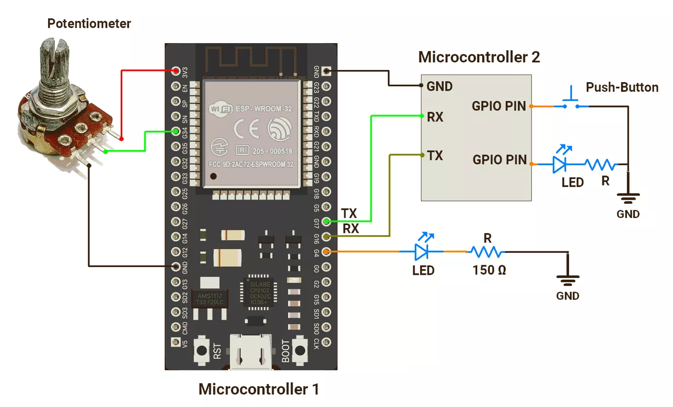
ESP32 Hardware Connection
- Microcontroller1 Connections
- LED1
- Connected to digital pin 4 using a 150Ω resistor in series with the LED to limit current through it.
- Potentiometer
- Terminal 1 → VCC.
- Terminal 2 → Pin 34.
- Terminal 3 → GND.
- LED1
- Microcontroller2 Connections
- Push Button Switch
- One terminal is connected to digital pin 15, and the other is connected to GND.
- Use an internal pull-up resistor on digital pin 15 to avoid the floating state of the pin.
- LED2
- Connected to digital pin 4 using a 150Ω resistor in series with the LED to limit current through it.
- Push Button Switch
- UART Connection
- ESP32 as Microcontroller1
- Pin 16 (RX) → Microcontroller2 TX
- Pin 17 (TX) → Microcontroller2 RX
- ESP32 as Microcontroller2
- Connections are the vice-versa of Microcontroller1 (TX ↔ RX).
- ESP32 as Microcontroller1
Connect either ESP32 to the PC via USB cable for programming/debugging.
ESP32 Circuit Diagram
1)ESP32 as Microcontroller1
2)ESP32 as Microcontroller2
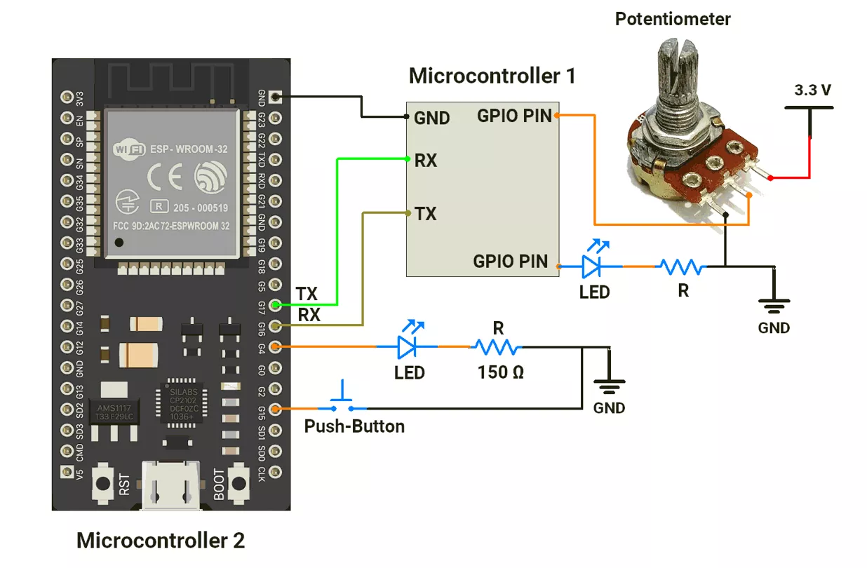
Note: When interfacing UART devices operating at different voltages (e.g., 5 V ↔ 3.3 V), always use a voltage level shifter to ensure safe logic levels and reliable communication.
ESP32 Firmware Implementation
1) Code of ESP32 as Microcontroller1
#define POTENTIOMETER_PIN 34  // Analog input pin for potentiometer
#define LED_PIN 4             // Digital output pin for LED

uint16_t potValue = 0;  // Stores raw ADC value from potentiometer

// Predefined maximum ADC value (12-bit ESP32: 0–4095) split into two bytes
uint8_t adcMaxLowerByte = 4095;
uint8_t adcMaxUpperByte = 4095 >> 8;

// Variables to hold the split potentiometer reading (LSB/MSB)
uint8_t adcLowerByte = 0;
uint8_t adcUpperByte = 0;

void setup() {
  pinMode(LED_PIN, OUTPUT);                   // LED pin as output
  Serial.begin(115200);                       // Serial communication
  Serial2.begin(115200, SERIAL_8N1, 16, 17);  //Start UART2 @115200 baudrate, 8N1 format(8 bit data, No parity bit 1, stop bit), RX=GPIO16, TX=GPIO17

  void loop() {
    // Check if data is received from microcontroller2 over UART2
    if (Serial2.available()) {
      uint8_t receivedByte = Serial2.read();  // Read incoming command byte

      // Command 'T' → toggle LED state
      if (receivedByte == 'T') {
        digitalWrite(LED_PIN, !digitalRead(LED_PIN));
        // Send data to serial monitor
        Serial.print("LED is ");
        Serial.println(digitalRead(LED_PIN) ? "ON" : "OFF");
      }

      // Command 0 → read potentiometer value and split into 2 bytes
      if (receivedByte == 0) {
        potValue = analogRead(POTENTIOMETER_PIN);  // Read 12-bit ADC value
        adcLowerByte = potValue & 0xFF;            // Extract lower 8 bits
        adcUpperByte = potValue >> 8;              // Extract upper 4 bits
        Serial2.write(0);                          // Acknowledge reception
        Serial.flush();                            // Wait until all data in the TX buffer is transmitted (does NOT clear RX buffer)
      }

      // Command 1 → send ADC max value (lower byte)
      if (receivedByte == 1) {
        Serial2.write(adcMaxLowerByte);
      }

      // Command 2 → send ADC max value (upper byte)
      if (receivedByte == 2) {
        Serial2.write(adcMaxUpperByte);
      }

      // Command 3 → send latest potentiometer value (lower byte)
      if (receivedByte == 3) {
        Serial2.write(adcLowerByte);
      }

      // Command 4 → send latest potentiometer value (upper byte)
      if (receivedByte == 4) {
        Serial2.write(adcUpperByte);
      }
    }
  }
Code Explanation
Functionality:
Reads the potentiometer value and provides it over UART when requested by MCU2. Also toggles the LED when it receives 'T'.
Logic
- Setup
- Configure the LED pin as an output.
- Start UART2 on pins 16 (RX) and 17 (TX).
- Loop
- If UART receives '
T' → toggle LED ON/OFF. - If UART receives
0→ sead potentiometer (ADC 12-bit), split into two bytes, send them back. - If UART receives
1→ send ADC maximum lower byte. - If UART receives
2→ send ADC maximum upper byte. - If UART receives
3→ send potentiometer lower byte (last read). - If UART receives
4→ send potentiometer upper byte (last read).
- If UART receives '
2)Code of ESP32 as Microcontroller2
#define LED_PIN 4
#define BUTTON_PIN 15
#define DEBOUNCE_DELAY 50  // debounce time in ms

  uint8_t rxBuffer[10];  // buffer for UART received data

bool last_button_state = HIGH;     // previous raw button state
bool current_button_state = HIGH;  // stable debounced state
unsigned long last_debounce_time = 0;

unsigned long previousMillis = 0;  // timer for periodic UART task

void setup() {
  pinMode(LED_PIN, OUTPUT);
  pinMode(BUTTON_PIN, INPUT_PULLUP);  // button active LOW

  Serial.begin(115200);
  Serial2.begin(115200, SERIAL_8N1, 16, 17);  // UART2: RX=16, TX=17

  // attach pin with frequency & resolution
  if (!ledcAttach(LED_PIN, 1000, 12)) {
    Serial.println("Error: ledcAttach failed");
  }
}

void loop() {
  // If button is pressed (debounced), send trigger 'T'
  if (is_debounced_press(BUTTON_PIN)) {
    Serial2.write('T');
  }

  // Every 100 ms perform UART exchange
  if ((millis() - previousMillis) > 100) {
    previousMillis = millis();

    // Flush any leftover bytes in UART RX buffer
    while (Serial2.available()) {
      Serial2.read();
    }

    // Request/receive 5 bytes from other board
    for (uint8_t i = 0; i < 5; i++) {
      Serial2.write(i);  // send request index
      while (Serial2.available() < 1)
        ;                            // wait for response
      rxBuffer[i] = Serial2.read();  // store received byte
      delay(1);                      // small gap
    }

    // Extract ADC max and ADC current value from received bytes
    uint8_t adcMaxLower = rxBuffer[1];
    uint8_t adcMaxUpper = rxBuffer[2];
    uint8_t adcLower = rxBuffer[3];
    uint8_t adcUpper = rxBuffer[4];

    uint16_t adcMaxValue = (adcMaxUpper << 8) | adcMaxLower;
    uint16_t adcValue = (adcUpper << 8) | adcLower;

    Serial.print("Received ADC Value: ");
    Serial.println(adcValue);

    // Map ADC value to 12-bit PWM range and update LED brightness
    uint16_t brightness = map(adcValue, 0, adcMaxValue, 0, 4095);
    ledcWrite(LED_PIN, brightness);  // write duty cycle to pin
    delay(10);
  }
}

// Button debounce routine
bool is_debounced_press(int pin) {
  bool reading = digitalRead(pin);

  // Reset debounce timer on state change
  if (reading != last_button_state) {
    last_debounce_time = millis();
  }
  last_button_state = reading;

  // Check if stable for debounce delay
  if ((millis() - last_debounce_time) > DEBOUNCE_DELAY) {
    if (reading != current_button_state) {
      current_button_state = reading;
      if (current_button_state == LOW) {  // pressed
        return true;
      }
    }
  }
  return false;
}
Code Explanation
Functionalty
Reads button, sends 'T' to MCU1 to toggle its LED, requests potentiometer values from MCU1, and uses them to control PWM brightness of its own LED.
Logic
- Setup
- Configure the LED pin for PWM (1 kHz, 12-bit).
- Configure the button with a pull-up.
- Start UART2 on pins 16 (RX) and 17 (TX).
- Loop
- If the button is pressed (debounced) → send '
T' to MCU1. - Every 100 ms:
- Clear leftover UART bytes.
- Request 5 values (0–4) from MCU1 (protocol).
- Store responses in buffer.
- Reconstruct:
adcMaxValue(max ADC = 4095)adcValue(current potentiometer reading)
- Map potentiometer value → 12-bit PWM (0–4095).
- Update LED brightness with
ledcWrite().
- If the button is pressed (debounced) → send '
We are using the Arduino UNO development board and programming it using the Arduino IDE.
- Before uploading, make sure to select “Arduino UNO” as the board to ensure correct settings and compatibility.
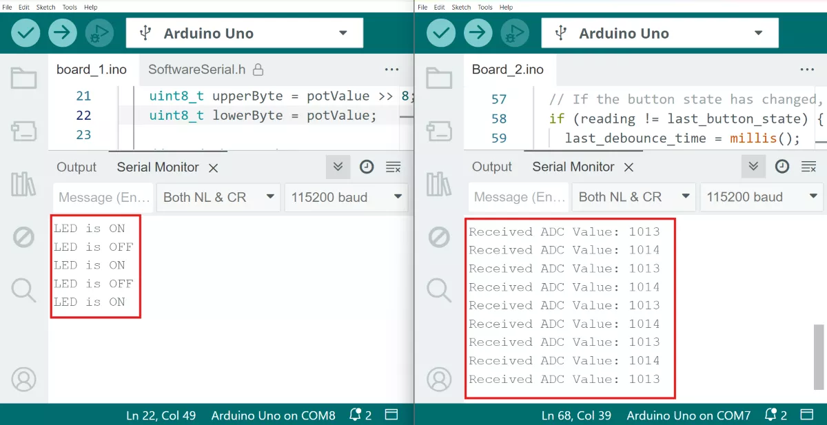
In this task, two Arduino UNO boards communicate via UART (Serial Communication) to control the brightness of LED2 and toggle LED1 ON and OFF.
Both Arduinos will log the data as follows:
- Arduino Microcontroller2 prints the received ADC values [0 to 1023].
- Arduino Microcontroller1 prints the LED1 status [ON or OFF].
For proper UART communication between two controllers, both must use the same baud rate (e.g., 9600, 4800, 115200).
Arduino UNO Hardware Connection
- Microcontroller 1 Connections
- LED1
- Connected to digital pin 7 using a 330Ω resistor in series with LED to limit current through it.
- Potentiometer
- Terminal 1 → VCC.
- Terminal 2 → Pin A0.
- Terminal 3 → GND.
- LED1
- Microcontroller 2 Connections
- Push Button Switch
- One terminal is connected to digital pin 2, and the other is connected to GND.
- Use an internal pull-up resistor on digital pin 2 to avoid the floating state of the pin.
- LED2
- Connected to digital pin 7 using a 330Ω resistor in series with the LED to limit current through it.
- Push Button Switch
- UART Connection (SoftwareSerial):
- The Microcontroller1 D3 pin (RX) is connected to the Microcontroller2 D4 pin (TX).
- The Microcontroller1 D4 pin (TX) is connected to the Microcontroller2 D3 pin (RX)
- Connect the Arduino UNO to the PC via USB cable.
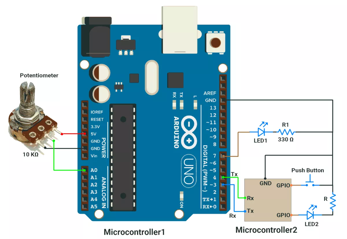
Arduino UNO Circuit Diagram
1)Arduino UNO as Microcontroller 1
2)Arduino UNO as Microcontroller 2
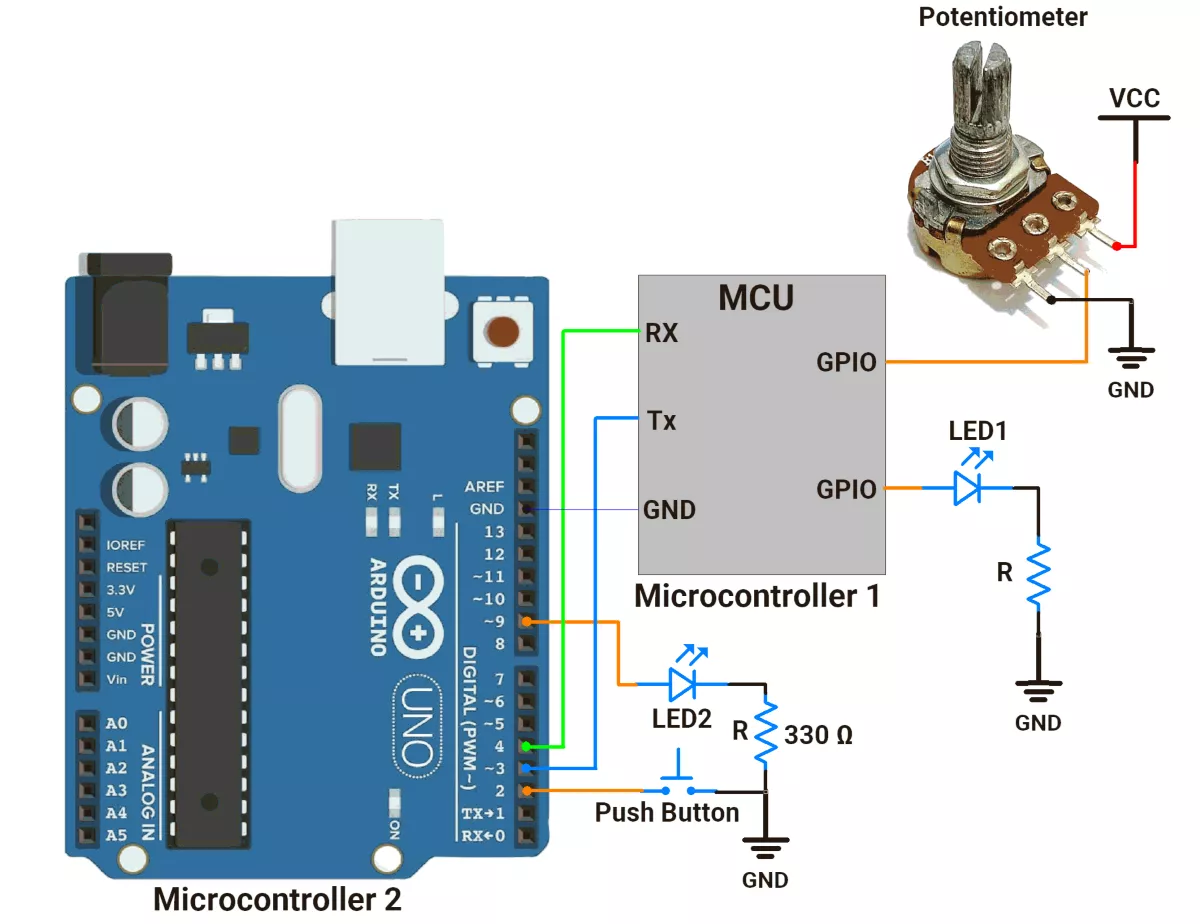
Note: When interfacing UART devices operating at different voltages (e.g., 5 V ↔ 3.3 V), always use a voltage level shifter to ensure safe logic levels and reliable communication.
Arduino UNO Firmware Implementation
- Arduino UNO has only one hardware serial module using Tx (Pin 1) and Rx (Pin 0).
- These pins are also used for USB communication with the Serial Monitor.
- Using the same pins for both tasks, data logging on the serial monitor, and data transmission between two Arduino UNO boards can cause data conflicts.
- To prevent this, we assign different pins for board-to-board communication.
- The SoftwareSerial library helps create additional Tx and Rx pins.
1) Code of Arduino UNO as a microcontroller 1:
#include <SoftwareSerial.h>

#define POTENTIOMETER A0
#define LED_PIN 7

SoftwareSerial mySerial(3, 4);  // 3-RX, 4-TX (For communication with Board 2)

uint16_t potValue = 0;

uint8_t adcMaxLowerByte = 1023;       // Lower byte
uint8_t adcMaxUpperByte = 1023 >> 8;  // Upper byte

uint8_t adcLowerByte = 0;  // Lower byte
uint8_t adcUpperByte = 0;  // Upper byte

void setup() {
  pinMode(LED_PIN, OUTPUT);
  mySerial.begin(115200);  // Initialize software Serial communication
  Serial.begin(115200);    // Initialize Hardware Serial communication
}

void loop() {

  if (mySerial.available()) {
    uint8_t receivedByte = mySerial.read();  // Read a single byte

    if (receivedByte == 'T') {
      digitalWrite(LED_PIN, !digitalRead(LED_PIN));  // Toggle LED state
      Serial.print("LED is ");
      Serial.println(digitalRead(LED_PIN) ? "ON" : "OFF");  // Print state
    }
    if (receivedByte == 0) {
      potValue = analogRead(A0);  // Read potentiometer value (0-1023)
      adcLowerByte = potValue;       // Lower byte
      adcUpperByte = potValue >> 8;  // Upper byte
      mySerial.write('0');
    }

    if (receivedByte == 1) {
      mySerial.write(adcMaxLowerByte);
    }

    if (receivedByte == 2) {
      mySerial.write(adcMaxUpperByte);
    }

    if (receivedByte == 3) {
      mySerial.write(adcLowerByte);
    }

    if (receivedByte == 4) {
      mySerial.write(adcUpperByte);
    }
  }
}
2) Code of Arduino UNO as a microcontroller 2:
#include <SoftwareSerial.h>

#define LED_PIN 9
#define SWITCH_PIN 2
#define DEBOUNCE_DELAY 50  // debounce delay

uint8_t previousValue = 0;

unsigned long previousMillis = 0;

uint8_t txBuffer[20];
uint8_t rxBuffer[10];

uint8_t rxIndex = 0;


bool last_button_state = 1;            // Previous button state (1: not pressed, 0: pressed)
bool current_button_state = 1;         // Current button state
unsigned long last_debounce_time = 0;  // Timestamp of the last button state change

uint16_t adcValue = 0;
SoftwareSerial mySerial(3, 4);  // 3-RX, 4-TX (For communication with Board 1)

void setup() {
  pinMode(LED_PIN, OUTPUT);
  pinMode(SWITCH_PIN, INPUT_PULLUP);
  mySerial.begin(115200);  // Initialize Software Serial communication
  Serial.begin(115200);  // Initialize Hardware Serial communication
}

void loop() {

  if (is_debounced_press(SWITCH_PIN)) {

    mySerial.write("T\n");  // Send command to toggle LED
  }

  if((millis() - previousMillis) > 100){
    previousMillis = millis();
    rxIndex = 0;
    for(uint8_t i = 0; i < 5; i++){
      mySerial.write(i);
      while(mySerial.available() < 1);
      rxBuffer[i] = mySerial.read();
      delay(1);
    }

    uint8_t adcMaxValueLowerByte = rxBuffer[1];  // Read the lower byte
    uint8_t adcMaxValueUpperByte = rxBuffer[2];  // Read the upper byte

    uint8_t adcValueLowerByte = rxBuffer[3];  // Read the lower byte
    uint8_t adcValueUpperByte = rxBuffer[4];  // Read the upper byte

    // Combine the two bytes into a 16-bit value
    uint16_t adcMaxValue = (adcMaxValueUpperByte << 8) | adcMaxValueLowerByte;

    // Combine the two bytes into a 16-bit value
    uint16_t adcValue = (adcValueUpperByte << 8) | adcValueLowerByte;

    // print received brightness value on serial monitor
    Serial.print("Received ADC Value: ");
    Serial.println(adcValue);

    //Map received ADC value to 0 to 255
    uint8_t brightness = map(adcValue,0,adcMaxValue,0,255);

    analogWrite(LED_PIN, brightness);  // Adjust LED brightness

  }
}

// Checks if the button is pressed and debounced.

bool is_debounced_press(int button_pin) {
  int reading = digitalRead(button_pin);

  // If the button state has changed, reset the debounce timer
  if (reading != last_button_state) {
    last_debounce_time = millis();
  }
  last_button_state = reading;
  // If the button state is stable for more than 50 msec the debounce delay, update the state.
  if ((millis() - last_debounce_time) > DEBOUNCE_DELAY) {
    if (reading != current_button_state) {
      current_button_state = reading;


      if (current_button_state == 0) {
        return true;  // valid press detected
      }
    }
  }
  return false;  // No valid press detected
}
Code Explanation
Includes & Setup:
#include <SoftwareSerial.h>: Enables software serial communication for both boards.SoftwareSerial mySerial(3, 4);: Creates a software serial instance on pins 3 (RX) and 4 (TX) for inter-board communication.mySerial.begin(115200);: Initializes software serial communication at 115200 baud rate.Serial.begin(115200);: Initializes hardware serial for debugging/logging at 115200 baud rate.
Microcontroller 1 (Transmitter/Receiver) Functionality:
- Potentiometer Reading:
- Continuously reads analog value from A0 (potentiometer)
- Splits the 10-bit ADC value (0-1023) into upper and lower bytes for transmission
- Message Handling:
- Listens for incoming bytes from Board2 via software serial
- Implements a simple protocol where different byte values trigger different actions:
- '
T': Toggles LED1 and prints status ("ON"/"OFF") to hardware serial 0: Triggers a new potentiometer reading1-4: Responds with specific bytes of ADC data (max value or current value)
- '
- Data Transmission:
- Sends requested bytes (ADC values) back to Board2 when specific commands are received
Microcontroller 2 (Receiver/Transmitter) Functionality:
- Button Handling:
- Uses debounce logic (
is_debounced_press()) to detect valid button presses - When pressed, sends 'T' command to Board1 to toggle its LED
- Uses debounce logic (
- Periodic Data Request:
- Every 100ms, initiates a data request sequence:
- Sends numbers 0-4 sequentially to Board1
- Waits for and reads corresponding responses
- Reconstructs ADC values from received bytes
- Every 100ms, initiates a data request sequence:
- LED Control:
- Maps received ADC value to PWM range (0-255)
- Applies the mapped value to LED2 using
analogWrite() - Prints received ADC value to the hardware serial for monitoring
- Debounce Function:
is_debounced_press()implements proper debouncing:- Tracks button state changes
- Only registers a press after a stable LOW state for >50ms
- Returns true for valid presses
Output
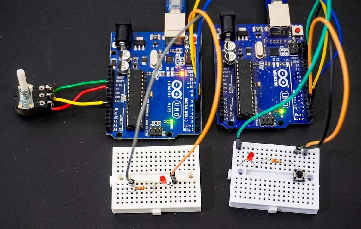
UART communication between two Arduino UNO boards
Hardware Setup
Screen-Shot Of Output
Video