
55. Code Conversion Logic
Question.4
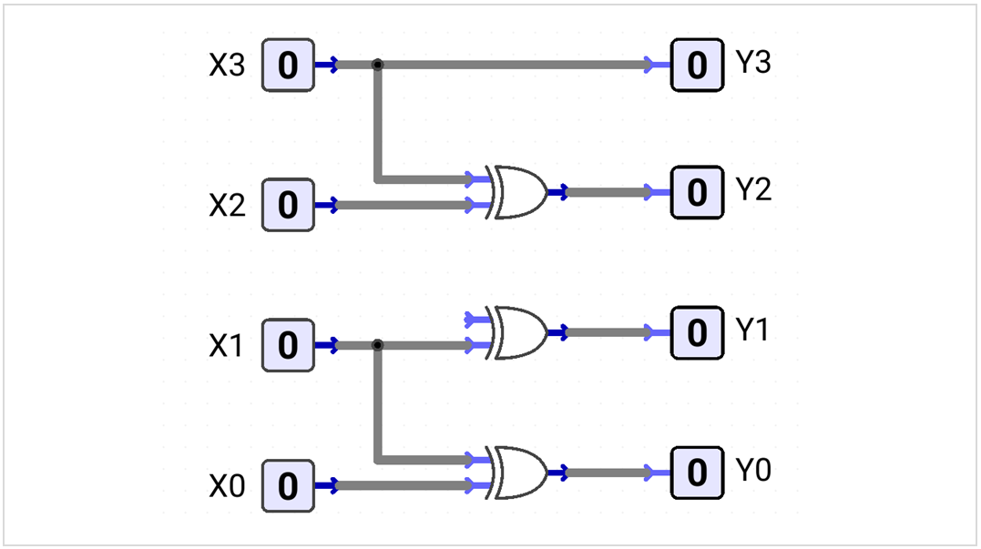
The circuit is intended to convert 4-bit Binary X3X2X1X0 into Gray code Y3Y2Y1Y0, but one input of the XOR gate producing Y1 is disconnected. Which signal should be connected to the open input?
Code conversion circuits change digital data from one code representation to another while preserving the represented value.
Input Code → Combinational Converter → Output CodeCode Reference Tables
For decimal digits 0–9, Binary and BCD use the same 4-bit patterns.
| Decimal | Binary | BCD | Gray | Excess-3 | Hex |
|---|---|---|---|---|---|
| 0 | 0000 | 0000 | 0000 | 0011 | 0 |
| 1 | 0001 | 0001 | 0001 | 0100 | 1 |
| 2 | 0010 | 0010 | 0011 | 0101 | 2 |
| 3 | 0011 | 0011 | 0010 | 0110 | 3 |
| 4 | 0100 | 0100 | 0110 | 0111 | 4 |
| 5 | 0101 | 0101 | 0111 | 1000 | 5 |
| 6 | 0110 | 0110 | 0101 | 1001 | 6 |
| 7 | 0111 | 0111 | 0100 | 1010 | 7 |
| 8 | 1000 | 1000 | 1100 | 1011 | 8 |
| 9 | 1001 | 1001 | 1101 | 1100 | 9 |
Decimal 10–15
Binary, Gray, and Hex use a single 4-bit/digit representation; BCD and Excess-3 encode each decimal digit separately.
| Decimal | Binary | BCD | Gray | Excess-3 | Hex |
|---|---|---|---|---|---|
| 10 | 1010 | 0001 0000 | 1111 | 0100 0011 | A |
| 11 | 1011 | 0001 0001 | 1110 | 0100 0100 | B |
| 12 | 1100 | 0001 0010 | 1010 | 0100 0101 | C |
| 13 | 1101 | 0001 0011 | 1011 | 0100 0110 | D |
| 14 | 1110 | 0001 0100 | 1001 | 0100 0111 | E |
| 15 | 1111 | 0001 0101 | 1000 | 0100 1000 | F |
Binary and BCD Conversion
For a single decimal digit 0–9, 4-bit Binary and BCD use the same bit pattern, so no conversion logic is required. For values greater than 9, BCD encodes each decimal digit separately.
Decimal 5: Binary = 0101, BCD = 0101
Decimal 12: Binary = 1100, BCD = 0001 0010
Binary and Gray Conversion
Binary-to-Gray
Copy the MSB directly. XOR each pair of adjacent input bits.
G3 = B3
G2 = B3 ⊕ B2
G1 = B2 ⊕ B1
G0 = B1 ⊕ B0
Binary 0010 → Gray 0011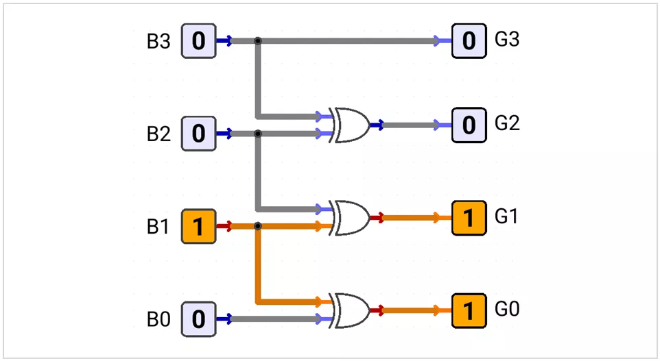
Gray-to-Binary
Copy the Gray MSB directly. Generate each remaining output bit by XORing the previous output bit with the next Gray bit.
B3 = G3
B2 = B3 ⊕ G2
B1 = B2 ⊕ G1
B0 = B1 ⊕ G0
Gray 0011 → Binary 0010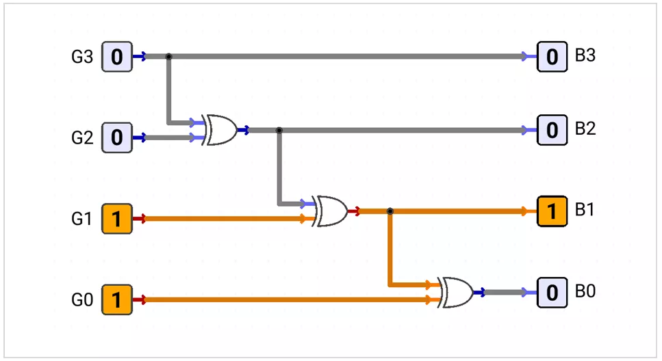
BCD and Excess-3 Conversion
Excess-3 represents each decimal digit by adding binary 0011 (decimal 3) to its corresponding 4-bit BCD value.
BCD + 0011 → Excess-3
Excess-3 − 0011 → BCD
BCD-to-Excess-3
Excess-3 = BCD + 0011
0011 + 0011 = 0110
For BCD inputs B3_B2_B1_B0, define:
X = B1 + B0

E3 = B3 + B2 · X
E2 = B2 ⊕ X
E1 = (B1 ⊕ B0)'
E0 = B0'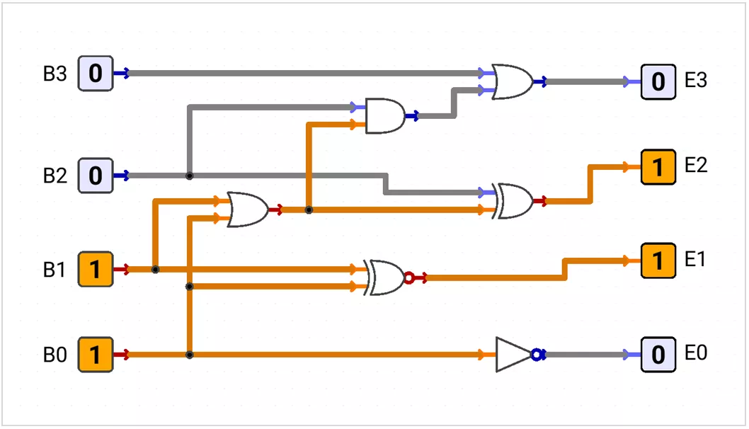
Excess-3-to-BCD
BCD = Excess-3 − 0011

0110 − 0011 = 0011
For inputs E3_E2_E1_E0, define:
Y = E1 · E0

B3 = E3 · (E2 + Y)
B2 = (E2 ⊕ Y)'
B1 = E1 ⊕ E0
B0 = E0'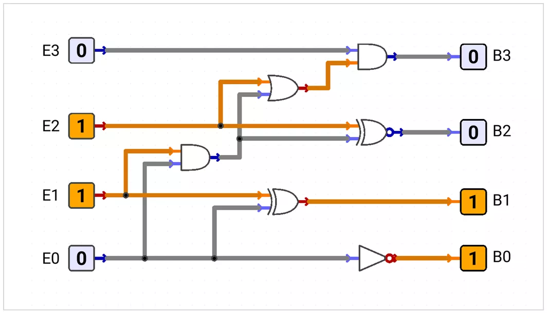
BCD-to-7-Segment Decoder
A BCD-to-7-segment decoder converts a BCD digit 0–9 into seven control signals a–g used to display the corresponding decimal digit. The following uses an active-HIGH common-cathode display.
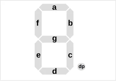
Common-cathode display: 1 = Segment ON, 0 = Segment OFF7-segment code order: a b c d e f g
| Decimal | BCD | abcdefg |
|---|---|---|
| 0 | 0000 | 1111110 |
| 1 | 0001 | 0110000 |
| 2 | 0010 | 1101101 |
| 3 | 0011 | 1111001 |
| 4 | 0100 | 0110011 |
| 5 | 0101 | 1011011 |
| 6 | 0110 | 1011111 |
| 7 | 0111 | 1110000 |
| 8 | 1000 | 1111111 |
| 9 | 1001 | 1111011 |
Minimized Active-HIGH Segment Equations
a = B1 + B3 + B2 · B0 + B2' · B0'
b = B2' + B1 · B0 + B1' · B0'
c = B0 + B2 + B1'
d = B3 + B1 · B0' + B1 · B2' + B2' · B0' + B2 · B0 · B1'
e = B1 · B0' + B2' · B0'
f = B3 + B2 · B0' + B2 · B1' + B1' · B0'
g = B3 + B1 · B0' + B1 · B2' + B2 · B1'
Note: BCD inputs 1010–1111 are unused for decimal digits and may be treated as don't-care conditions when simplifying the logic.
BCD-to-7-Segment Circuit
BCD 0011 (3) → 7-Segment 1111001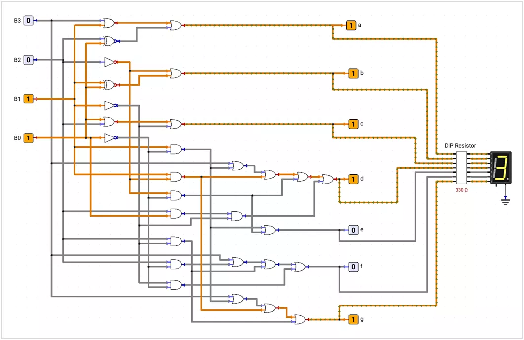
Note: For a common-anode display, the segment-control logic is inverted: 0 = Segment ON and 1 = Segment OFF.