
55. Code Conversion Logic
Question.9
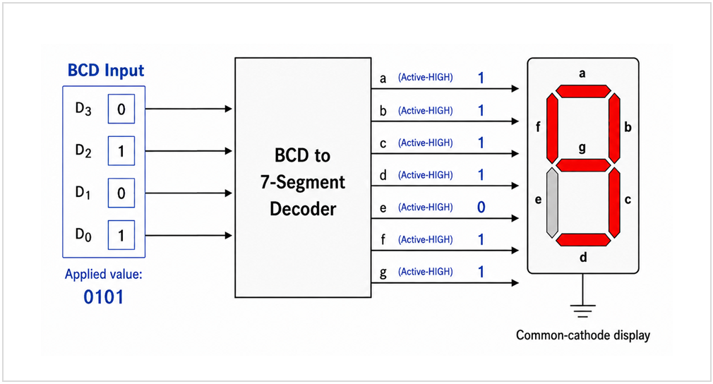
During testing of a common-cathode BCD-to-7-segment decoder, BCD input 0101 is applied. The measured active-HIGH segment outputs are:
abcdefg = 1111011Which segment output is incorrect?
Code conversion circuits change digital data from one code representation to another while preserving the represented value.
Input Code → Combinational Converter → Output CodeCode Reference Tables
For decimal digits 0–9, Binary and BCD use the same 4-bit patterns.
| Decimal | Binary | BCD | Gray | Excess-3 | Hex |
|---|---|---|---|---|---|
| 0 | 0000 | 0000 | 0000 | 0011 | 0 |
| 1 | 0001 | 0001 | 0001 | 0100 | 1 |
| 2 | 0010 | 0010 | 0011 | 0101 | 2 |
| 3 | 0011 | 0011 | 0010 | 0110 | 3 |
| 4 | 0100 | 0100 | 0110 | 0111 | 4 |
| 5 | 0101 | 0101 | 0111 | 1000 | 5 |
| 6 | 0110 | 0110 | 0101 | 1001 | 6 |
| 7 | 0111 | 0111 | 0100 | 1010 | 7 |
| 8 | 1000 | 1000 | 1100 | 1011 | 8 |
| 9 | 1001 | 1001 | 1101 | 1100 | 9 |
Decimal 10–15
Binary, Gray, and Hex use a single 4-bit/digit representation; BCD and Excess-3 encode each decimal digit separately.
| Decimal | Binary | BCD | Gray | Excess-3 | Hex |
|---|---|---|---|---|---|
| 10 | 1010 | 0001 0000 | 1111 | 0100 0011 | A |
| 11 | 1011 | 0001 0001 | 1110 | 0100 0100 | B |
| 12 | 1100 | 0001 0010 | 1010 | 0100 0101 | C |
| 13 | 1101 | 0001 0011 | 1011 | 0100 0110 | D |
| 14 | 1110 | 0001 0100 | 1001 | 0100 0111 | E |
| 15 | 1111 | 0001 0101 | 1000 | 0100 1000 | F |
Binary and BCD Conversion
For a single decimal digit 0–9, 4-bit Binary and BCD use the same bit pattern, so no conversion logic is required. For values greater than 9, BCD encodes each decimal digit separately.
Decimal 5: Binary = 0101, BCD = 0101
Decimal 12: Binary = 1100, BCD = 0001 0010
Binary and Gray Conversion
Binary-to-Gray
Copy the MSB directly. XOR each pair of adjacent input bits.
G3 = B3
G2 = B3 ⊕ B2
G1 = B2 ⊕ B1
G0 = B1 ⊕ B0
Binary 0010 → Gray 0011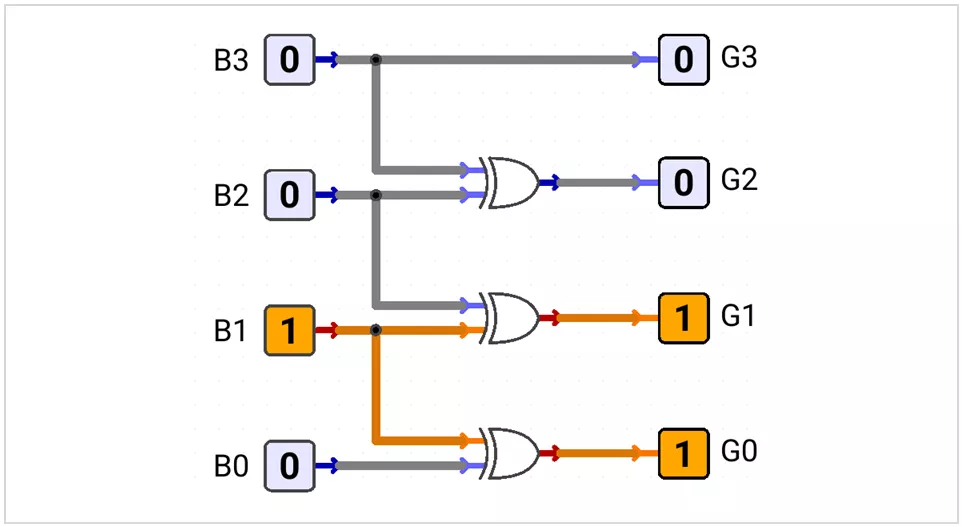
Gray-to-Binary
Copy the Gray MSB directly. Generate each remaining output bit by XORing the previous output bit with the next Gray bit.
B3 = G3
B2 = B3 ⊕ G2
B1 = B2 ⊕ G1
B0 = B1 ⊕ G0
Gray 0011 → Binary 0010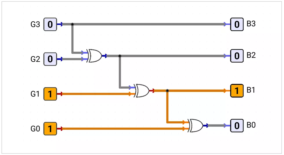
BCD and Excess-3 Conversion
Excess-3 represents each decimal digit by adding binary 0011 (decimal 3) to its corresponding 4-bit BCD value.
BCD + 0011 → Excess-3
Excess-3 − 0011 → BCD
BCD-to-Excess-3
Excess-3 = BCD + 0011
0011 + 0011 = 0110
For BCD inputs B3_B2_B1_B0, define:
X = B1 + B0

E3 = B3 + B2 · X
E2 = B2 ⊕ X
E1 = (B1 ⊕ B0)'
E0 = B0'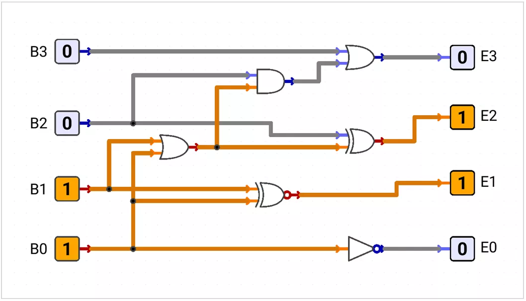
Excess-3-to-BCD
BCD = Excess-3 − 0011

0110 − 0011 = 0011
For inputs E3_E2_E1_E0, define:
Y = E1 · E0

B3 = E3 · (E2 + Y)
B2 = (E2 ⊕ Y)'
B1 = E1 ⊕ E0
B0 = E0'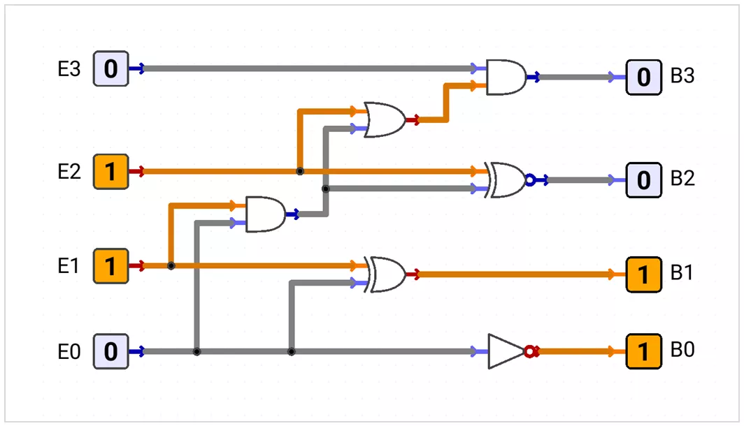
BCD-to-7-Segment Decoder
A BCD-to-7-segment decoder converts a BCD digit 0–9 into seven control signals a–g used to display the corresponding decimal digit. The following uses an active-HIGH common-cathode display.
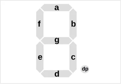
Common-cathode display: 1 = Segment ON, 0 = Segment OFF7-segment code order: a b c d e f g
| Decimal | BCD | abcdefg |
|---|---|---|
| 0 | 0000 | 1111110 |
| 1 | 0001 | 0110000 |
| 2 | 0010 | 1101101 |
| 3 | 0011 | 1111001 |
| 4 | 0100 | 0110011 |
| 5 | 0101 | 1011011 |
| 6 | 0110 | 1011111 |
| 7 | 0111 | 1110000 |
| 8 | 1000 | 1111111 |
| 9 | 1001 | 1111011 |
Minimized Active-HIGH Segment Equations
a = B1 + B3 + B2 · B0 + B2' · B0'
b = B2' + B1 · B0 + B1' · B0'
c = B0 + B2 + B1'
d = B3 + B1 · B0' + B1 · B2' + B2' · B0' + B2 · B0 · B1'
e = B1 · B0' + B2' · B0'
f = B3 + B2 · B0' + B2 · B1' + B1' · B0'
g = B3 + B1 · B0' + B1 · B2' + B2 · B1'
Note: BCD inputs 1010–1111 are unused for decimal digits and may be treated as don't-care conditions when simplifying the logic.
BCD-to-7-Segment Circuit
BCD 0011 (3) → 7-Segment 1111001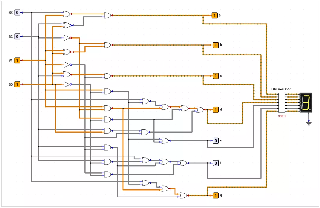
Note: For a common-anode display, the segment-control logic is inverted: 0 = Segment ON and 1 = Segment OFF.