
43. 4-to-1 Data Selector
Design a 4-to-1 Multiplexer (MUX) circuit that acts as a data routing switch. The system routes one of four data inputs to a single output based on a 2-bit select signal from a controller.
Constraints:
- Inputs: Data lines (A, B, C, D), Select lines (S1, S0)
- Outputs: Data output (Y)
- Components: Must build everything from scratch using basic gates only. Ready-made multiplexer blocks are forbidden.
Behavioral Reference:
| S1 | S0 | A | B | C | D | Output Y |
|---|---|---|---|---|---|---|
| 0 | 0 | 1 | X | X | X | 1 |
| 0 | 0 | 0 | X | X | X | 0 |
| 0 | 1 | X | 1 | X | X | 1 |
| 0 | 1 | X | 0 | X | X | 0 |
| 1 | 0 | X | X | 1 | X | 1 |
| 1 | 0 | X | X | 0 | X | 0 |
| 1 | 1 | X | X | X | 1 | 1 |
| 1 | 1 | X | X | X | 0 | 0 |
(Note: X represents a "don't care" condition)
Combinational circuits produce outputs only from the present input values. They do not store previous states and normally do not require a clock.
Inputs → Combinational Logic → OutputsCombinational Logic Optimization
The same combinational function can often be represented by different Boolean expressions. Logic optimization finds a simpler equivalent expression, reducing the required gates and logic levels.
Common methods include:
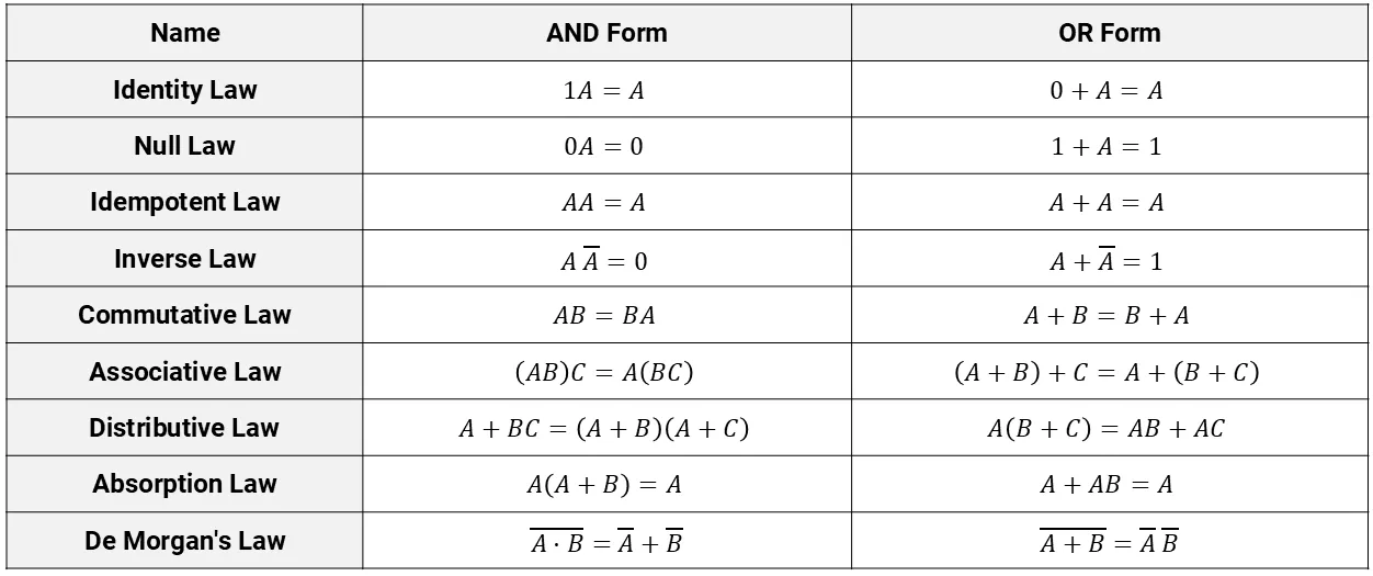
- Boolean algebra: Simplifies expressions using Boolean laws.
- Karnaugh Map (K-map): Groups related input combinations to eliminate unnecessary variables.
- Don’t-care conditions: Uses unused input combinations when they help simplify the function.
Boolean Algebra Laws and Rules:
SOP and POS Forms
Boolean functions are commonly written in two forms:
| Form | Structure | K-Map Method |
|---|---|---|
| SOP – Sum of Products | Product terms ORed together | Group 1s |
| POS – Product of Sums | Sum terms ANDed together | Group 0s |
SOP: F = A' · C + A · B
POS: F = (A + C) · (A' + B)
In SOP, each product term represents a condition that makes F = 1. In POS, each sum term is derived from a condition where F = 0.
3-Variable K-Map Example
For inputs A, B, and C:
F(A,B,C) = Σm(1,3,6,7)Here, Σm identifies the minterms where F = 1.
In a 3-variable K-map, A selects the row and BC selects the column. The columns follow Gray-code order:
00 → 01 → 11 → 10This ensures that adjacent cells differ in only one variable.
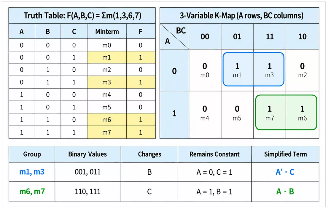
For SOP simplification, adjacent 1s are grouped in the largest possible groups of 1, 2, 4, 8, ... cells. A variable that changes within a group is eliminated; variables that remain constant form the simplified term.
m1, m3 → A' · Cm6, m7 → A · B
Each group is a condition that can make F = 1, so the terms are combined using OR (+):
F = A' · C + A · BPOS from the Same K-Map
For POS simplification, group the cells where F = 0:
F(A,B,C) = ΠM(0,2,4,5)Here, ΠM identifies the maxterms where F = 0.
m0, m2 → (A + C)m4, m5 → (A' + B)
Each group forms a sum term. The sum terms are combined using AND (·):
F = (A + C) · (A' + B)Thus, the same function can be represented as:
SOP: F = A' · C + A · B
POS: F = (A + C) · (A' + B)
Optimized Logic Circuit
The simplified SOP expression can be implemented using logic gates:
F = A' · C + A · B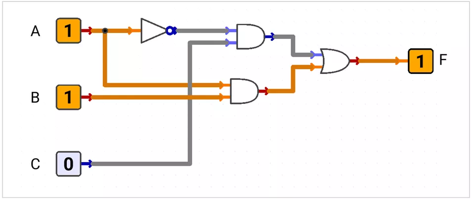
Parity Bit Generator
A parity bit generator generates an extra bit so the total number of 1s becomes either even or odd.
Even Parity
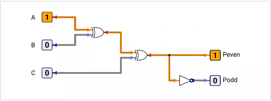
Peven = A ⊕ B ⊕ C
- Even number of data 1s → Peven = 0
- Odd number of data 1s → Peven = 1
Odd Parity
Podd = (A ⊕ B ⊕ C)'
- Even number of data 1s → Podd = 1
- Odd number of data 1s → Podd = 0
Example: ABC = 100
Peven = 1→ total number of 1s = 2 → even parityPodd = 0→ total number of 1s = 1 → odd parity
Encoder
An encoder converts an active input line into a binary code.
A priority encoder encodes only the highest-priority active input.
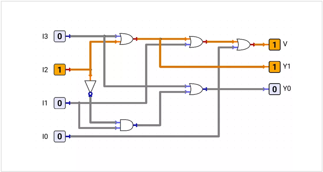
Priority: I3 > I2 > I1 > I0
| I3 | I2 | I1 | I0 | V | Y1 | Y0 |
|---|---|---|---|---|---|---|
| 0 | 0 | 0 | 0 | 0 | X | X |
| 0 | 0 | 0 | 1 | 1 | 0 | 0 |
| 0 | 0 | 1 | X | 1 | 0 | 1 |
| 0 | 1 | X | X | 1 | 1 | 0 |
| 1 | X | X | X | 1 | 1 | 1 |
V = I3 + I2 + I1 + I0
Y1 = I3 + I2
Y0 = I3 + I2' · I1
In input columns, X means a lower-priority input does not affect the result. When V = 0, Y1_Y0 is invalid and may be treated as don't-care.
Example: 0111 → highest active input = I2 → Y1_Y0 = 10, V = 1
Decoder
A decoder converts an n-bit input code into one selected output among up to 2ⁿ output lines.
2 input bits → 4 outputs
3 input bits → 8 outputs
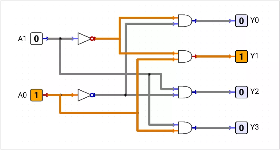
2-to-4 Active-HIGH Decoder
| A1 | A0 | Y3 | Y2 | Y1 | Y0 |
|---|---|---|---|---|---|
| 0 | 0 | 0 | 0 | 0 | 1 |
| 0 | 1 | 0 | 0 | 1 | 0 |
| 1 | 0 | 0 | 1 | 0 | 0 |
| 1 | 1 | 1 | 0 | 0 | 0 |
Y0 = A1'·A0'
Y1 = A1'·A0
Y2 = A1·A0'
Y3 = A1·A0Example: A1_A0 = 10 → Y2 = 1
Active-LOW Decoder
An active-LOW decoder selects one output by making it LOW while the other outputs remain HIGH.
Y0 = (A1'·A0')'
Y1 = (A1'·A0)'
Y2 = (A1·A0')'
Y3 = (A1·A0)'
Active-LOW outputs are commonly used for chip-select and control signals.
Multiplexer
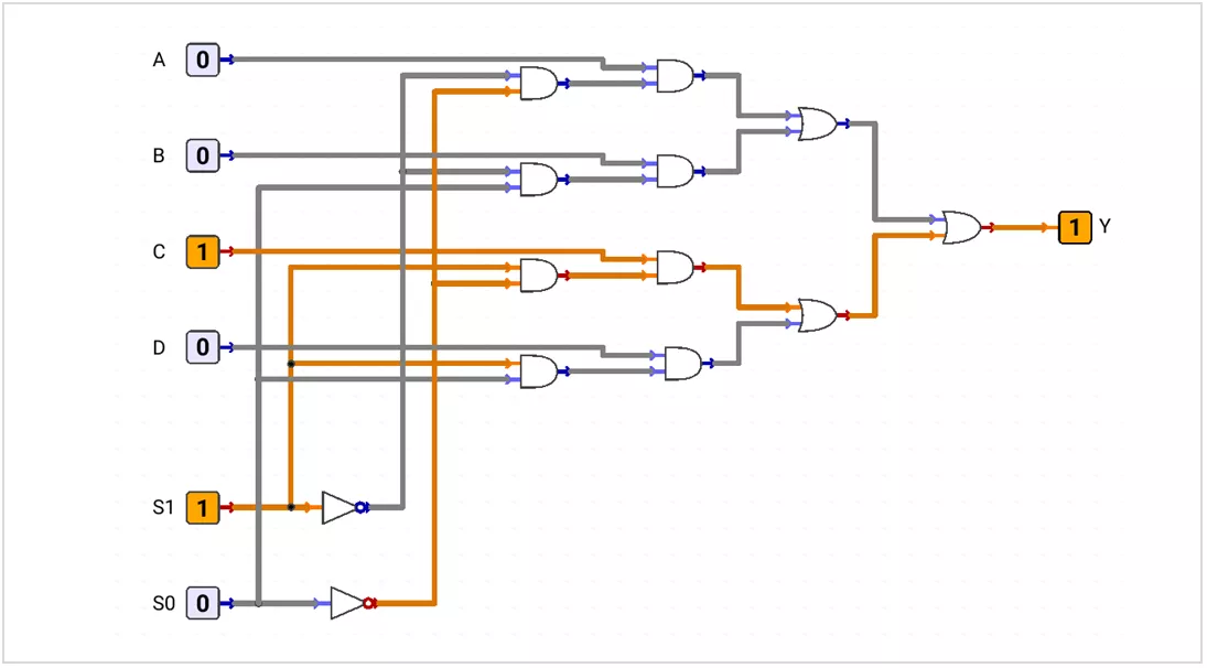
A Multiplexer (MUX) is a data selector. It routes one of several data inputs to one output.
Many Data Inputs → One OutputA 4-to-1 MUX uses data inputs A, B, C, D and select lines S1, S0.
| S1 | S0 | Y |
|---|---|---|
| 0 | 0 | A |
| 0 | 1 | B |
| 1 | 0 | C |
| 1 | 1 | D |
Y = A·S1'·S0' + B·S1'·S0 + C·S1·S0' + D·S1·S0Example: S1_S0 = 10 → Y = C
Demultiplexer
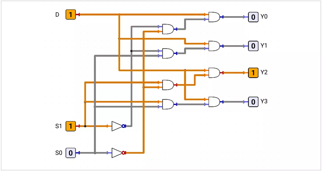
A Demultiplexer (DEMUX) is a data distributor. It routes one input D to one selected output.
One Data Input → One Selected Output| S1 | S0 | Selected Output |
|---|---|---|
| 0 | 0 | Y0 = D |
| 0 | 1 | Y1 = D |
| 1 | 0 | Y2 = D |
| 1 | 1 | Y3 = D |
Y0 = D·S1'·S0'
Y1 = D·S1'·S0
Y2 = D·S1·S0'
Y3 = D·S1·S0Example: S1_S0 = 10 → Y2 = D
Quick Comparison
| Circuit | Signal Flow | Function |
|---|---|---|
| MUX | Many inputs → one output | Select data |
| DEMUX | One input → one selected output | Route data |
| Decoder | Binary code → one selected output | Select output line |
| Priority Encoder | Active inputs → binary code | Encode highest-priority input |
Timing Note: Combinational outputs change after the propagation delay of the logic path.