17. Binary to Gray Code Converter
Design a Binary to Gray Code Converter that converts a 4-bit binary input into its 4-bit Gray code equivalent.
Requirements
- Module name:
bin2gray4 - Inputs:
bin_in[3:0]
- Outputs:
gray_out[3:0]
Expected behavior (full truth table)
| bin | gray | bin | gray | bin | gray | bin | gray |
|---|---|---|---|---|---|---|---|
| 0000 | 0000 | 0100 | 0110 | 1000 | 1100 | 1100 | 1010 |
| 0001 | 0001 | 0101 | 0111 | 1001 | 1101 | 1101 | 1011 |
| 0010 | 0011 | 0110 | 0101 | 1010 | 1111 | 1110 | 1001 |
| 0011 | 0010 | 0111 | 0100 | 1011 | 1110 | 1111 | 1000 |
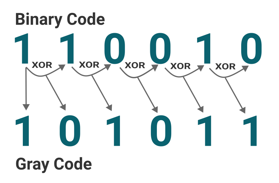
Note - Binary to Gray conversion
The most significant bit (MSB) of the Gray code is the same as the MSB of the binary input. Each subsequent bit of the Gray code is obtained by XORing the current bit of the binary input with the previous bit.
Hierarchical Verilog Design
- Concept: Designs are built as a hierarchy of modules. A higher-level module instantiates lower-level ones (like PCB → IC → flip-flop).
- Each module definition is standalone, not nested.
- Hierarchy enables modularity, reuse, and scalability.
- Hierarchical names use dot
.notation:top.u1.u2.signal.
Modules – The Core of Verilog
Syntax:
module <name> #(parameter ... ) (port list); // declarations // functionality endmodule- Modules describe behavior, structure, or both.
- Can contain:
- Ports (
input,output,inout) - Nets / regs
- Continuous assignments
- Procedural blocks (initial/always)
- Ports (
macromoduleis an alias formodule(rarely used).
Declaring & Instantiating Modules
- Declaration: always starts with
module … endmodule. Instantiation:
mod_name inst_name (.port1(sig1), .port2(sig2)); // named mapping mod_name inst_name (sig1, sig2); // ordered mapping- Multiple instances allowed in the same module.
Port Mapping Styles
By order: Ports matched in the order declared.
adder u1 (a, b, sum);⚠️ Risky: Errors occur if order changes.
By name: Ports explicitly named.
adder u1 (.x(a), .y(b), .z(sum));✅ Recommended: Safer against future changes.
Port Declaration Keywords
input– read-only inside the module.output– driven inside, observed outside.inout– bidirectional (used in buses like I²C, data buses).- Defaults & caveats:
- If type not specified, ports default to net type
wire. - Must explicitly declare
regif procedural assignment needed. Example:
module m(input clk, input [7:0] data, output reg q, inout bus);
- If type not specified, ports default to net type
Logic States with Operators
Four states:
0→ logic zero1→ logic onez/Z→ high impedance (tri-stated)x/X→ unknown (simulation only!)
Hardware reality: Only 0, 1, Z exist. X indicates indeterminate logic (conflict, uninitialized, timing issue) in simulation.
NOT (~)
~0 = 1,~1 = 0~x = x,~z = x
AND (&)
- If any input is 0 → result = 0
- If all inputs are 1 → result = 1
- Otherwise →
x
OR (|)
- If any input is 1 → result = 1
- If all inputs are 0 → result = 0
- Otherwise →
x
XOR (^)
- If both inputs known → normal XOR (
1if odd # of 1’s) - If any input is
x/z→ result =x
Derived
- NAND = NOT(AND)
- NOR = NOT(OR)
- XNOR = NOT(XOR)
💡 Quick Memory Aid
- AND is “pessimistic” → 0 dominates.
- OR is “optimistic” → 1 dominates.
- XOR is “suspicious” → any
x/zpoisons result. - NOT just flips 0/1, turns unknowns into
x.
Vectors
Declaring Vectors
Syntax:
<type> [msb:lsb] <name>;- msb = most significant bit index
- lsb = least significant bit index
Example:
wire [7:0] data_bus; // 8-bit wide bus (data_bus[7]..data_bus[0]) reg [15:0] acc; // 16-bit register- Indexing direction:
[7:0]→ descending (bit 7 = MSB, bit 0 = LSB) — most common.[0:7]→ ascending (bit 0 = MSB, bit 7 = LSB) — allowed, but less used.- Both are legal in IEEE 1364-2005.
⚠️ Gotcha: A vector’s indexing direction matters in part-selects and concatenations.
Bit Selection
Access individual bits:
data_bus[0] // LSB acc[15] // MSB- Index must be constant in synthesis (simulation allows variable indices, but not synthesizable in many tools).
Part Selection
- Extract a subset of contiguous bits.
Syntax:
vector[msb:lsb] // fixed part-select vector[base +: width] // indexed part-select (2001+) vector[base -: width]Examples:
data_bus[7:4]   // upper nibble of 8-bit bus
acc[11:8]       // 4 bits from acc

// Indexed part-select (IEEE 1364-2001 & 2005)
acc[3 +: 4]     // acc[6:3]  (4 bits starting at index 3, ascending)
acc[7 -: 4]     // acc[7:4]  (4 bits descending from 7)
✅ Indexed part-select avoids confusion when ranges flip.
Concatenation {}
- Combines multiple signals or vectors into a larger one.
Syntax:
{expr1, expr2, expr3}Examples:
wire [3:0] a = 4'b1010; wire [3:0] b = 4'b1100; wire [7:0] c; assign c = {a, b}; // c = 1010_1100- Replication operator:
{N{expr}}repeats an expressionNtimes.Example:
{4{1'b1}}    // 1111 (4-bit all ones)
{2{a}}       // {a,a} → duplicates a vector
Mixed Concatenation
Scalars and vectors can mix:
{a[3:0], 2'b11, b[1]} // concatenates 4+2+1 = 7 bits- Concatenation result width = sum of operand widths.
Assignments & Truncation
- If RHS wider than LHS → truncated (MSBs dropped).
If RHS narrower → zero-filled (if unsigned) or sign-extended (if signed).
reg [3:0] x;
x = 8'hAB;   // x = 4'hB  (truncated)
Vector Operations
- Bitwise operators apply bit-by-bit:
& | ^ ~ ^~ ~^Example:
assign out = a & b; // AND each bit
- Reduction operators collapse vector → single bit:
&a,|a,^a,~&a,~|a,~^aExample:
wire parity = ^data_bus; // XOR all bits → parity
- Shift operators:
a << n,a >> n(logical shift, fill with zeros).>>>(arithmetic right shift, preserves sign bit for signed values).Example:
reg signed [7:0] s = -8'd8;  // 1111_1000
$display("%b", s >>> 2);     // 1111_1110 = -2
Corner Cases & Pitfalls
Out-of-range index: Returns
x(unknown).wire [3:0] a = 4'b1010; $display("%b", a[10]); // x- Empty concatenation: Illegal in Verilog-2005.
- Mix signed/unsigned: Width/sign extension rules can surprise. Always cast explicitly if needed.
Number Representation <size>'<base><value>
- Format:
<size>: number of bits<base>:b(binary),o(octal),d(decimal),h(hex)<value>: digits
Examples:
4'b1010   // 4-bit binary
8'hFF     // 8-bit hex
'd25      // 32-bit decimal (unsized default)
Sized vs Unsized
- Sized: Width is explicit →
4'b1010 - Unsized: Defaults to 32 bits →
'hF= 32-bit hex F.
Defaults
- Base: Decimal if unspecified.
- Case: Base (
d/h/o/b) and digits are case-insensitive. - Readability:
_allowed →16'b1010_1100_1111_0000.
Negative Numbers
Preferred syntax:
-8'd6 // 8-bit signed decimal -6 4'shF // signed 4-bit hex = -1- Note:
8'd-6is illegal. - Signed constants (
'sd) are sign-extended when assigned.
Real Number Representation
- Decimal:
12.34,0.1 - Scientific:
1.2e3,4.5E-2 - Must have digit before and after decimal point.
_can be used for readability:236.123_763_e-12- Follows IEEE 754 double precision.