81. High-Frequency Measurement
After analyzing the task, we need to measure a square wave frequency above 100 kHz, which can be done using two approaches:
- Input Capture Mode of Timer.
- The timer captures the exact time when a signal edge (rising or falling) occurs.
- By measuring the time difference between two consecutive edges, the period of one cycle can be calculated.
- This method provides high accuracy and is ideal for measuring high-frequency signals or short pulse widths.
- Timer Counter Mode (External Pulse Counting):
- The timer is configured to count external pulses arriving at a specific pin.
- By counting how many pulses occur within a fixed time window (e.g., 1 second), the frequency can be determined.
- This approach is simple and effective for moderate to high-frequency signals where precise timing of each edge is not required.
So, by considering the above points, we can implement the task.
Below are the solutions to the given task using different microcontrollers
- ESP32
- Arduino UNO
- We are using the ESP32 DevKitC v4 development board and programming it using the Arduino IDE.
- Before uploading, make sure to select “ESP32 Dev Module” as the board to ensure correct settings and compatibility.
- The ESP32 has four general-purpose hardware timers, primarily designed for time-keeping and interrupt-driven tasks (e.g., delays, periodic events, scheduling), and cannot count external pulses.
- For an external pulse counting application, there is dedicated hardware in the ESP32 called PCNT.
- So we will use the PCNT hardware module to perform the given task.
Note: Although the task mentions using a timer, as per our understanding, ESP32’s general-purpose timers don't have the ability to count external pulses. So use the PCNT (Pulse Counter) peripheral, which is dedicated hardware for reliable external pulse counting.
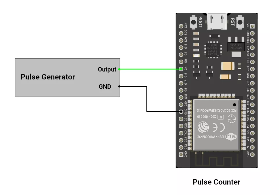
Circuit Connection
- Connect external pulses to GPIO pin 4.
Circuit Connection
Firmware Implementation
Code
#include <Arduino.h>
#include "driver/pcnt.h"

#define PCNT_INPUT_GPIO 4          // Input pin where pulses are received
#define PCNT_UNIT_USED PCNT_UNIT_0 // Use hardware pulse counter Unit 0
#define SAMPLE_TIME_MS 10          // Measurement window in milliseconds
  int16_t count = 0;


void setup() {
  Serial.begin(115200);
  delay(200);
  Serial.println("Frequency Measurement ");

  // Configure PCNT hardware
  pcnt_config_t pcnt_config = {};                 // Initialize config structure
  pcnt_config.pulse_gpio_num = PCNT_INPUT_GPIO;   // Pulse input pin
  pcnt_config.ctrl_gpio_num  = PCNT_PIN_NOT_USED; // No direction control pin
  pcnt_config.channel        = PCNT_CHANNEL_0;    // Use channel 0 of the unit
  pcnt_config.unit           = PCNT_UNIT_USED;    // Use PCNT unit 0

  pcnt_config.pos_mode = PCNT_COUNT_INC;          // Increment count on rising edge
  pcnt_config.neg_mode = PCNT_COUNT_DIS;          // Ignore falling edges
  pcnt_config.lctrl_mode = PCNT_MODE_KEEP;        // Keep mode (no direction change)
  pcnt_config.hctrl_mode = PCNT_MODE_KEEP;        // Keep mode (no direction change)

  // Set counter upper and lower limits (16-bit signed range)
  pcnt_config.counter_h_lim = 32767;
  pcnt_config.counter_l_lim = -32768;

  // Apply configuration to PCNT hardware
  ESP_ERROR_CHECK(pcnt_unit_config(&pcnt_config));

  //  Initialize counter
  pcnt_counter_pause(PCNT_UNIT_USED);  // Stop counter during setup
  pcnt_counter_clear(PCNT_UNIT_USED);  // Reset count to zero
  pcnt_counter_resume(PCNT_UNIT_USED); // Start counting pulses

  Serial.println("PCNT initialized on GPIO4.");
}

void loop() {
  int16_t count = 0;

  // Measure pulse count in fixed time window
  pcnt_counter_clear(PCNT_UNIT_USED);  // Reset count
  delay(SAMPLE_TIME_MS);               // Wait for sampling period
  pcnt_get_counter_value(PCNT_UNIT_USED, &count); // Read count after delay

  //  Calculate frequency
  // Convert counts per sample time to frequency in Hz
  float freq = (float)count * (1000.0f / SAMPLE_TIME_MS);

  //  Display result
  Serial.printf("Frequency: %.2f Hz\n",freq);
  delay(1000); // Wait 1 second before next update
}
Code Explanation
void setup()
- Configures PCNT Unit 0 to count rising edges on GPIO 4.
- Initializes counter limits and starts the unit.
void Loop()
- Clears the counter, waits 10 ms, then reads how many pulses were counted.
- Converts that count into frequency.
-
float freq = (float)count * (1000.0f / SAMPLE_TIME_MS);
-
- Prints both count and frequency on the Serial Monitor.
Serial.printf("Frequency: %.2f Hz\n",freq);
ESP32 PCNT practical frequency range: ~1 MHz to 3–4 MHz (typical), in good hardware conditions with no heavy filtering.
We are using the Arduino UNO development board and programming it using the Arduino IDE.
- Before uploading, make sure to select “Arduino UNO” as the board to ensure correct settings and compatibility.
Approach 1 (Input Capture Mode)
Input Capture Mode (ATmega328P - Arduino UNO)
- What It Does: Captures the exact timer value (TCNT)when an external signal edge occurs on PD6 (ICP1 pin).
- How It Works:
- A hardware timer (Timer1) runs continuously.
- When a signal edge (rising/falling) happens on PD6 (ICP1 pin), the timer value is saved in ICR1.
- By capturing two consecutive rising edges, we get the signal period (T).
- Frequency is calculated as: F=1/T.
- Why Use It?: More precise frequency measurement than basic timing functions.
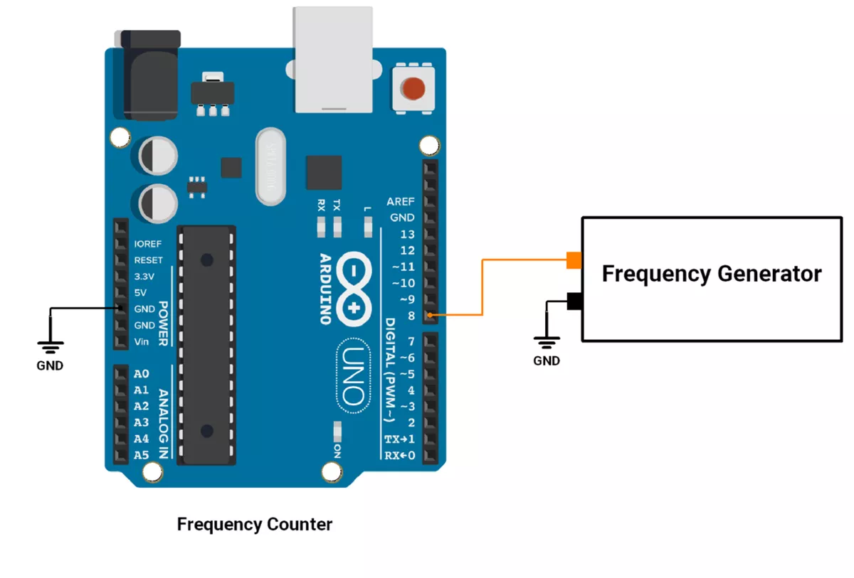
Hardware Connection
- Input Capture Mode
- Signal Source: Connect the high-frequency signal (greater than 100 kHz) to Pin 8 (ICP1) of the Arduino UNO. This pin is the input capture pin for Timer1.
- Arduino UNO: Ensure proper grounding between the signal source and the Arduino.
Firmware
- In this approach, Timer1 is configured in Input Capture Mode to measure the period T of the signal.
- The frequency F is then calculated using the formula: F = 1/T
- The Input Capture Mode captures the timestamp of two consecutive rising edges of the signal, and the difference between these timestamps gives the period T.
Code
volatile uint8_t overflowCount = 0;
volatile uint32_t t = 0;
uint16_t  firstCapture = 0;
uint16_t secondCapture = 0;

void setup() {
  Serial.begin(115200);
  TCCR1A = 0;
  TCCR1B = (1 << ICES1) | (1 << CS10);  // Rising edge, No prescaler (16 MHz)

}

void loop() {
  if (countSignal()) {
    float timeMicroseconds = t * 0.0625;  // Convert clock cycles to microseconds (1/16 MHz)
    float frequency = 1e6 / timeMicroseconds;  // Convert period to frequency

    Serial.print("Frequency: ");
    Serial.print(frequency);
    Serial.print(" Hz, Time: ");
    Serial.print(timeMicroseconds);
    Serial.println(" µs");
  }

  delay(500);
}

bool countSignal() {
  cli();  // Disable interrupts

  overflowCount = 0;  //  Reset overflow counter before starting
  TIFR1 |= (1 << ICF1) | (1 << TOV1);  // Clear input capture & overflow flags

  // Wait for first rising edge
  while (!(TIFR1 & (1 << ICF1)));

  firstCapture = ICR1;  // Store first capture value
  TIFR1 = (1 << ICF1);  // Clear flag

  // Wait for second rising edge while counting overflows
  while (!(TIFR1 & (1 << ICF1))) {
    if (TIFR1 & (1 << TOV1)) {
      overflowCount++;
      TIFR1 = (1 << TOV1);  // Clear overflow flag
    }
  }

 secondCapture = ICR1;  // Store second capture

  sei();  // Re-enable interrupts

  // Correct time  calculation
  t = (overflowCount * 65536UL) + (secondCapture - firstCapture);

  return t > 0;  // Return true if valid measurement
}
Code Explanation
Setup (setup())
- Initializes serial communication (115200 baud rate) to display frequency values.
Main Loop (loop())
countSignal()is called to calculate the signal period.- Measures and prints frequency, then waits 1000 ms.
Signal Measurement (countSignal())
- Setup Timer1
- Disable interrupts →
cli(); - clear flags (overflow flag and input capture flag)
TIFR1 = (1 << ICF1) | (1 << TOV1);
- To configure rising edge detection and start Timer
TCCR1A = 0;TCCR1B = (1 << ICES1) | (1 << CS10);
- Disable interrupts →
- First Rising Edge
- Wait, record
firstCapture, and clear the flaguint16_t firstCapture = ICR1;
- Wait, record
- Second Rising Edge
- Wait while counting overflows, record secondCapture, then stop Timer1
uint16_t secondCapture = ICR1;
- Wait while counting overflows, record secondCapture, then stop Timer1
- Calculate Time
- Compute t using overflows and capture values.
t = (overflowCount * 65536UL) + (secondCapture - firstCapture);
- Compute t using overflows and capture values.
- Finish
- Re-enable interrupts and return true if a signal was detected.
sei();
- Re-enable interrupts and return true if a signal was detected.
Conclusion
- In Arduino UNO, the maximum clock frequency is 16MHz. So, 62.5 nanoseconds is for executing one instruction. That is why it is not possible to measure a signal >16MHz.
- Interrupt Handling Limitation (
attachInterrupt())- Interrupts introduce latency (~5 µs per ISR call).
- If an interrupt is triggered at 16 MHz, the CPU wouldn’t have time to handle it before the next pulse arrives.
- So in the given approach, we used a polling method for capturing rising edge. Which can calculate the frequency of 1.14MHz accurately without any error.
Why 1 MHz is the Maximum Detectable Frequency?
1️. After First Capture:
- Reads ICR1 (16-bit) → 2 cycles (125 ns)
- Clears ICF1 flag → 1 cycle (62.5 ns)
2️. Waiting for Second Capture:
- The while loop checks ICF1 every 8 cycles (500 ns @ 16 MHz)
- If an overflow occurs, handling it adds 4 more cycles (250 ns)
3️. Limit on Frequency Detection:
- To detect a full waveform (one period), the second capture must be accurate.
- Since the loop takes approximately 8 cycles (500 ns) per iteration, the system can reliably detect signals ≥ 1 µs period (≤ 1 MHz frequency).
- For frequencies > 1 MHz, the loop may miss transitions, causing incorrect measurements.
Conclusion: The approach is accurate up to 1 MHz but fails for higher frequencies due to the loop execution time.
Approach 2 (Counting Pulses using Timer counter)
Alternatively, we can count the number of rising edges of the signal in a fixed time interval (e.g., 1 second).
The frequency F is directly equal to the number of pulses counted in 1 second.
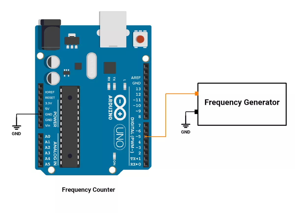
- Counting Pulses in 1 Second
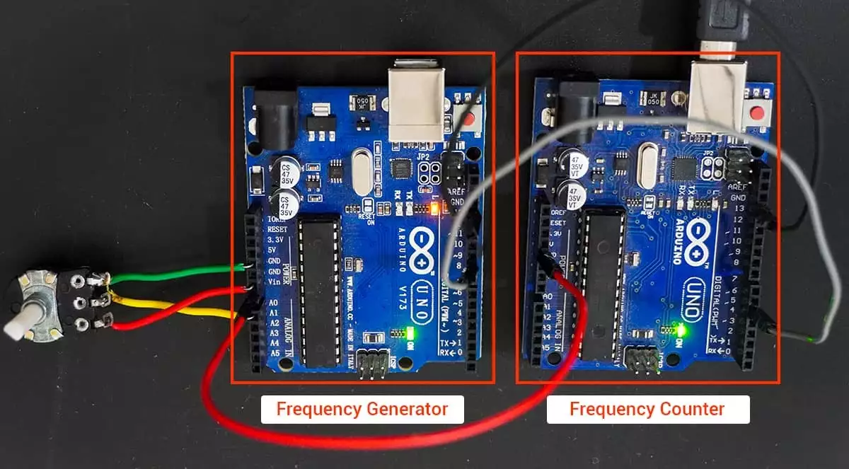
- Signal Source: Connect the high-frequency signal (greater than 100 kHz) to Digital Pin 5 (ICP1) of the Arduino UNO.
- Arduino UNO: Ensure proper grounding between the signal source and the Arduino.
Hardware Connection
Firmware
- In this approach, Timer1 is used as a counter to count the number of pulses on Digital Pin 5, while Timer2 is used to generate a 1-second time interval.
- The frequency is calculated as the number of cycles counted in 1 second.
- Frequency = No of cycles in 1 sec interval.
- Time Period = 1 / Frequency.
Code
uint8_t OldTimerA0, oldTimerB0, oldTimerMask;
volatile uint32_t timerTick = 0;
volatile uint16_t overflowCount = 0;
volatile bool countValue = false;
float frequency = 0, timePeriod = 0;
uint16_t count = 0;

void setup() {
  Serial.begin(115200);
}

void loop() {
  disableTimer0();   // Stop Timer0 to avoid conflicts
  startCount();      // Start frequency measurement

  while (!countValue);  // Wait for measurement to complete

  Serial.print("Frequency: ");
  Serial.print(frequency);
  Serial.println(" Hz");

  Serial.print("Time Period: ");
  Serial.print(timePeriod, 10);
  Serial.println(" Sec");

  enableTimer0();   // Restore Timer0
  delay(1000);      // Wait before next measurement
}

void disableTimer0() {
  OldTimerA0 = TCCR0A;
  oldTimerB0 = TCCR0B;
  oldTimerMask = TIMSK0;
  TCCR0A = TCCR0B = TIMSK0 = 0;  // Stop Timer0
}

void enableTimer0() {
  TCCR0A = OldTimerA0;
  TCCR0B = oldTimerB0;
  TIMSK0 = oldTimerMask;
}

void startCount() {
  cli();  // Disable interrupts

  // Configure Timer2 for 1-second measurement
  TCCR2A = (1 << WGM21);  // CTC mode
  TCCR2B = (1 << CS22) | (1 << CS21) | (1 << CS20);  // Prescaler 1024
  OCR2A = 156;  // 1-second interrupt
  TIMSK2 = (1 << OCIE2A);  // Enable Timer2 Compare Match Interrupt

  // Configure Timer1 for external pulse counting
  TCCR1A = 0;
  TCCR1B = (1 << CS12) | (1 << CS11) | (1 << CS10);  // External clock, rising edge
  TIMSK1 = (1 << TOIE1);  // Enable Timer1 overflow interrupt

  countValue = false;
  overflowCount = 0;
  TCNT1 = 0;
  sei();  // Enable interrupts
}

ISR(TIMER1_OVF_vect) {
  overflowCount++;  // Increment overflow count
}

ISR(TIMER2_COMPA_vect) {
  if (count == 100) {  // 100 interrupts = 1 second
    cli();  // Disable interrupts for calculation
    timerTick = ((uint32_t)overflowCount * 65536) + TCNT1;  // Total pulses
    frequency = timerTick;  // Frequency = total pulses in 1 second
    timePeriod = 1.0 / frequency;  // Time period

    // Stop timers
    TCCR1A = TCCR1B = TIMSK1 = 0;
    TCCR2A = TCCR2B = TIMSK2 = 0;
    TCNT1 = TCNT2 = 0;

    countValue = true;  // Set measurement complete flag
    count = 0;  // Reset counter
    sei();  // Re-enable interrupts
  }
  count++;
}
Code Explanation
setup()- Initializes serial communication at 115200 baud to display output.
loop()- Timer0 is disabled to avoid conflicts with
delay()andmillis(). - Measurement starts using
startCount(). - Prints the frequency & time period on the Serial Monitor.
- Re-enables Timer0 after measurement.
- Waits for 500 milliseconds before starting again.
- Timer0 is disabled to avoid conflicts with
startCount().- Disables interrupts (cli()) for safe configuration.
- Configures Timer2 to interrupt every 1/100th of a second.
- Configures Timer1 to count pulses from an external signal (on D5).
- Resets counters
(overflowCount = 0, TCNT1 = 0). - Enables interrupts (
sei()).
disableTimer0().- Disable the timer0.
enableTimer0().- Enable the timer0.
ISR(TIMER1_OVF_vect)- It increments the count after the timer gets overflown.
ISR(TIMER2_COMPA_vect)- Timer2 Interrupts 100 Times → 1 Second Elapsed.
cli();→ Disable interrupts to prevent data corruption.timerTick = ((uint32_t)overflowCount * 65536) + TCNT1;- Calculates total number of pulses counted in 1 second.
- Disables Timer1 & Timer2 (Stops counting).
- Computes frequency & time period:
frequency = timerTick;→ Pulses per second.timePeriod = 1.0 / frequency;→ Time period (seconds per pulse).
- Sets countValue = true; → Tells
loop()that measurement is complete. sei();→ Re-enables interrupts.
How Code works?
- Timer1 counts signal pulses on pin D5.
- Timer1 Overflow ISR increments
overflowCountwhen Timer1 overflows. - Timer2 ISR tracks elapsed time.
- After 1 second, Timer2 ISR:
- Stops all timers.
- Calculates frequency & time period.
- Prints results to Serial Monitor.
- Loop repeats every second.
Conclusion
- The Pulse Counting Method allows measurement of signals up to 8 MHz.
- For an 8 MHz signal, the error is approximately ±0.1 , making this approach highly accurate for a wide range of frequencies.
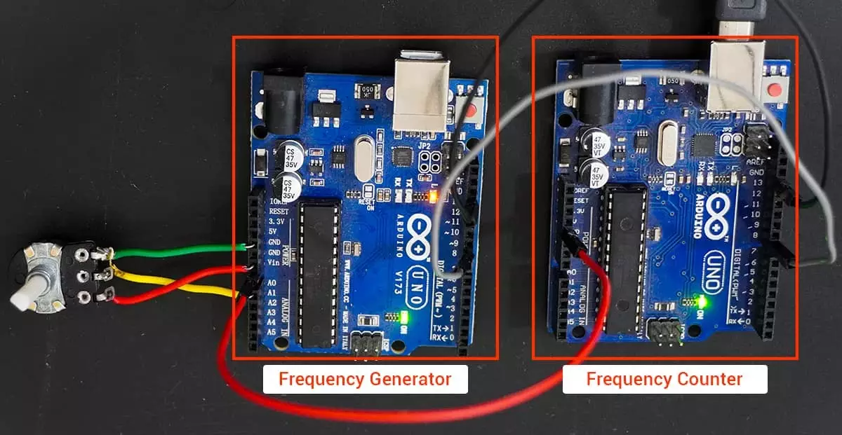
Output
Hardware Setup
Input Capture Mode
Counting Pulse Counting using Timer Counter
Video
Input Capture Mode
Counting Pulse Counting using Timer Counter